Table of Contents
Advertisement
Quick Links
Advertisement
Table of Contents

Related Manuals for TQ-Systems MBa8x


Summary of Contents for TQ-Systems MBa8x
- Page 1 MBa8x User's Manual MBa8x UM Rev. 0100 29.11.2021...
-
Page 2: Table Of Contents
User's Manual l MBa8x UM 0100 l © 2021, TQ-Systems GmbH Page i TABLE OF CONTENTS ABOUT THIS MANUAL ...................................... 6 Copyright and license expenses .................................. 6 Registered trademarks ....................................6 Disclaimer ..........................................6 Imprint ........................................... 6 Tips on safety ........................................7 Symbols and typographic conventions .............................. - Page 3 User's Manual l MBa8x UM 0100 l © 2021, TQ-Systems GmbH Page ii Thermal management ....................................43 Assembly ........................................... 44 SAFETY REQUIREMENTS AND PROTECTIVE REGULATIONS ......................46 EMC ............................................. 46 ESD ............................................46 Operational safety and personal security.............................. 46 CLIMATIC AND OPERATIONAL CONDITIONS ............................46 Protection against external effects ................................
- Page 4 User's Manual l MBa8x UM 0100 l © 2021, TQ-Systems GmbH Page iii TABLE DIRECTORY Table 1: Terms and Conventions ....................................7 Table 2: MBa8x interfaces and auxiliary functions .............................. 10 Table 3: Diagnostic and user interfaces .................................. 11 Table 4: Carrier board mating connectors ................................
- Page 5 User's Manual l MBa8x UM 0100 l © 2021, TQ-Systems GmbH Page iv FIGURE DIRECTORY Figure 1: Block diagram MBa8x ...................................... 9 Figure 2: Block diagram TQMa8x ....................................12 Figure 3: Block diagram Reset ...................................... 19 Figure 4: Placement push buttons on MBa8X ................................ 20 Figure 5: Block diagram GP push buttons ................................
- Page 6 User's Manual l MBa8x UM 0100 l © 2021, TQ-Systems GmbH Page v REVISION HISTORY Rev. Date Name Pos. Modification 0100 29.11.2021 Kreuzer First edition...
-
Page 7: About This Manual
Important Notice: Before using the MBa8x or parts of the MBa8x schematics, you must evaluate it and determine if it is suitable for your intended application. You assume all risks and liability associated with such use. TQ-Systems GmbH makes no other warranties including, but not limited to, any implied warranty of merchantability or fitness for a particular purpose. -
Page 8: Tips On Safety
Violation of this guideline may result in damage / destruction of the MBa8x and be dangerous to your health. -
Page 9: Naming Of Signals
User's Manual l MBa8x UM 0100 l © 2021, TQ-Systems GmbH Page 8 Naming of signals A hash mark (#) at the end of the signal name indicates a low-active signal. Example: RESET# If a signal can switch between two functions and if this is noted in the name of the signal, the low-active function is marked with a hash mark and shown at the end. -
Page 10: Brief Description
BRIEF DESCRIPTION This User's Manual describes the hardware of the MBa8x as of revision 02xx. The MBa8x is designed as a carrier board for the TQ- Minimodule TQMa8x and essentially serves as a design basis for customer-specific product ideas, as well as a platform to support development. -
Page 11: Mba8X Interfaces
User's Manual l MBa8x UM 0100 l © 2021, TQ-Systems GmbH Page 10 MBa8x interfaces The following interfaces and auxiliary functions are provided on the MBa8x: Table 2: MBa8x interfaces and auxiliary functions Interface Connector Type 3.5 mm jack MIC (mono, pink) - Page 12 User's Manual l MBa8x UM 0100 l © 2021, TQ-Systems GmbH Page 11 The MBa8x provides the following diagnostic and user interfaces: Table 3: Diagnostic and user interfaces Interface Component Remark 9 × Green LED Power LEDs (24 V, 12 V, 5 V-Mainboard, 5 V-Modul, 3,3 V, 3,3 V-Mainboard, 3,3 V-Modul, 1,8 V, 3,3 V-MPCIe, 1,5 V-MPCIe) 3 ×...
-
Page 13: Electronics
All other signals and buses provided by the TQMa8x are routed to 100 mil headers. The boot behaviour of the TQMa8x can be configured. The Boot-Mode configuration is set by a DIP switch on the MBa8x, see chapter 3.1.1.3. -
Page 14: Tqma8X Mating Connectors
If a different board-to-board distance is required, connectors with a different height can be used. Suitable types can be found on the manufacturer's website. To avoid damaging the connectors of the MBa8x or the TQMa8x while removing the TQMa8x, the use of the extraction tool MOZIA8X is strongly recommended. - Page 15 User's Manual l MBa8x UM 0100 l © 2021, TQ-Systems GmbH Page 14 3.1.1.2 TQMa8x pinout (continued) Table 5: Pinout TQMa8x connector X1 i.MX 8 ball DIR. Level Group Signal Signal Group Level DIR. i.MX 8 ball – – –...
- Page 16 User's Manual l MBa8x UM 0100 l © 2021, TQ-Systems GmbH Page 15 3.1.1.2 TQMa8x pinout (continued) Table 5: Pinout TQMa8x connector X1 (continued) i.MX 8 ball DIR. Level Group Signal Signal Group Level DIR. i.MX 8 ball USDHC1_DATA0 USB_SS_RX_P 1.8 V...
- Page 17 User's Manual l MBa8x UM 0100 l © 2021, TQ-Systems GmbH Page 16 3.1.1.2 TQMa8x pinout (continued) Table 6: Pinout TQMa8x connector X2 i.MX 8 ball DIR. Level Group Signal Signal Group Level DIR. i.MX 8 ball – – –...
- Page 18 User's Manual l MBa8x UM 0100 l © 2021, TQ-Systems GmbH Page 17 3.1.1.2 TQMa8x pinout (continued) Table 6: Pinout TQMa8x connector X2 (continued) i.MX 8 ball DIR. Level Group Signal Signal Group Level DIR. i.MX 8 ball BJ13 1.8 V...
- Page 19 User's Manual l MBa8x UM 0100 l © 2021, TQ-Systems GmbH Page 18 3.1.1.2 TQMa8x pinout (continued) Table 7: Pinout TQMa8x connector X3 i.MX 8 ball DIR. Level Group Signal Signal Group Level DIR. i.MX 8 ball – – –...
-
Page 20: Boot-Mode Configuration
User's Manual l MBa8x UM 0100 l © 2021, TQ-Systems GmbH Page 19 Boot-Mode configuration The Boot-Mode of the i.MX 8 is set with signals BOOT_MODE[5:0], which can be set with DIP switch SW1. The MBa8x supports the following TQMa8x boot sources. -
Page 21: General Purpose Push Buttons
General purpose push buttons For simple user inputs, the MBa8x offers two short-travel keys that are directly connected to the CPU. The signal lines have a 10 kΩ pull-up to V_1V8 and can be switched to ground by the push buttons. -
Page 22: Battery
(V_3V3_MPCIE, V_1V5_MPCIE). In addition, all USB ports at the VBUS voltages have LEDs. The LEDs for voltages below 3.3 V are connected to V_3V3 and switched by the respective voltage level via a transistor. The LEDs signal that the voltages have reached their typical end values and facilitate development on the MBa8x, as well as troubleshooting. -
Page 23: I 2 C Devices
C devices Two primary I2C buses are available. I2C1 connects all I2C devices on the module and the MBa8x. The voltage level of both I2C buses is 1.8 V. In order to be able to connect I2C devices with 3.3 V voltage level, there are level converters on the module and the mainboard. -
Page 24: Gpio Port Expander
A sensor of type SE97BTP with integrated EEPROM is available on the MBa8x for monitoring the temperature. This sensor is also installed on the TQMa8x. Both sensors are read out via I2C1. The address of the sensor on the MBa8x can be changed by reassembling resistors. -
Page 25: Temperature Sensor
3.12 Temperature sensor A temperature sensor SE97BTP is populated on the MBa8x to monitor the temperature. The same type of sensor is also used on the TQMa8x. Both sensors are read out via I2C1. The sensor address on the MBa8x can be changed by reassembling resistors. When changing the address, care must be taken to avoid address conflicts with existing I C devices. -
Page 26: Spdif
CAN-FD Both CAN interfaces of the MBa8x are directly connected to the CAN ports of the TQMa8x and are available at the two 3-pin connectors X18 and X19. Both interfaces are galvanically isolated up to 1 kV. The CAN interfaces are not galvanically isolated from each other. -
Page 27: Usb Debug
3.14.6 Ethernet The i.MX 8 CPU provides two independent RGMII interfaces. On the MBa8x, both interfaces are used to provide two Gigabit Ethernet ports. The PHYs support IEEE 802.3 10BASE-Te, 100BASE-TX, and 1000BASE-T. The I/O voltage of the RGMII signals is 1.8 V. Both PHYs are connected with their own PHY reset and interrupt signals. -
Page 28: Gpio
GPIO On the MBa8x, some GPIOs are provided by the TQMa8x. A distinction is made between general GPIO pins and those that are dedicated to the integrated auxiliary processors (SCU, ARM M4 CPUs). Some GPIOs are provided via a port expander. The voltage levels of some pins depend on other peripheral modules and may change during operation. -
Page 29: Display Interfaces
Embedded Display Port 1.4 On the MBa8x, the interface is implemented as DisplayPort as described in the i.MX8 QM/i.MX8 QXP Hardware Developers Guide. The series capacitors of 100 nF on the data lines are placed close to the module connector. ESD protection diodes are placed... -
Page 30: Hdmi In
User's Manual l MBa8x UM 0100 l © 2021, TQ-Systems GmbH Page 29 close to the DP socket. A self-resetting fuse of 2 A is provided on the DP_PWR pin (DP spec requires a fuse of max. 3 A). The connection of HDMI to this port is not provided! Note: NXP explains in the i.MX8 QM/i.MX8 QXP Hardware Developers Guide... -
Page 31: Mipi Csi
User's Manual l MBa8x UM 0100 l © 2021, TQ-Systems GmbH Page 30 TQMa8x MIPI_DSI[1..0] Incl. PWR_EN and PWM USB-Hub 2x USB BLT_EN, RESET (GPIO) TQ display adapter 1,8 V; 5 V; 12V Figure 15: Block diagram MIPI-DSI The pinout of the connector for the MIPI-DSI adapter was defined based on the existing TQ MIPI-CSI adapter. Control signals that are not included in the corresponding bus are provided via GPIO. -
Page 32: Mini Pcie
3.14.10 Mini PCIe A mini PCIe card slot is realised on the MBa8x. This is connected to the PCIe0 interface. The interface is wired with all signals provided by the standard (e.g. USB, I2C, PCIe). The clock is generated externally from a central location. -
Page 33: Pcie M.2
User's Manual l MBa8x UM 0100 l © 2021, TQ-Systems GmbH Page 32 Any standard-compliant mini-PCIE card can be used, as long as the necessary software drivers are available. TQMa8x SIM- Card PCIe0 (L1) I2C1 Mini-PCIe- Card USB- LEDs Figure 17: Block diagram Mini-PCIe The PCIE_PERST#, PCIE_WAKE# and PCIE_CLKREQ# signals have an IO voltage of 3.3 V. -
Page 34: Sata M.2
User's Manual l MBa8x UM 0100 l © 2021, TQ-Systems GmbH Page 33 TQMa8x Mini PCIe External PCIe ref. M.2 PCIe clock Figure 19: Clock supply PCIe All PCIe-CLK lines are routed with a differential impedance of 100 Ω. The clock line to the processor is not terminated to ground with 49.9 Ω... -
Page 35: Usb Otg
User's Manual l MBa8x UM 0100 l © 2021, TQ-Systems GmbH Page 34 USB1(3.0) USB1 n.c. USB-A socket Power VBUS TQMa8x OTG2 EN/OC switch VBUS USB-A socket USB3.0 USB2(3.0) USB2 n.c. MIPI- TUSB8041 USB3 USB3(2.0) PCIe M.2 DSI0 VBUS Power... -
Page 36: Sd Card
User's Manual l MBa8x UM 0100 l © 2021, TQ-Systems GmbH Page 35 TQMa8x VBUS_OTG1 OTG1_VBUS OTG1 DN/P DN/P (824014) USB 2.0 OTG V_5V_USB Switch MIC2026 VBUS_OTG1 VBUS_OTG1 (824014) Figure 22: Block diagram USB OTG The processor supports USB 2.0 with Hi-Speed, Full-Speed and Low-Speed. Depending on the software and hardware used, the effective read and write rates of the ports may vary. -
Page 37: Mikrobus
User's Manual l MBa8x UM 0100 l © 2021, TQ-Systems GmbH Page 36 The SDHC controller in the TQMa8x supports SD cards with UHS I transfer mode according to the SD card standard 3.1. Transfer rates of 104 Mbyte/s are thus possible. -
Page 38: Mba8X Headers
368,4 Hz 3.14.20 MBa8x headers The MBa8x provides four 100 mil headers. All signals, which are not used on the MBa8x, mainly low-speed signals such as GPIO, SPI and UART, are made available on these headers. Besides the signals, 1.8 V, 3.3 V, 5 V and 12 V are available on each header. The maximum current load of the individual voltages on the headers depends on the load on other connectors. - Page 39 User's Manual l MBa8x UM 0100 l © 2021, TQ-Systems GmbH Page 38 Level Group Signal Signal Group Level GPIO GPIO5_IO28 GPIO4_IO12 GPIO 1.8 V GPIO GPIO5_IO29 GPIO4_IO11 GPIO 1.8 V Power GPIO4_IO10 GPIO 1.8 V 1.8 V ESAI0 ESAI0_SCKT...
-
Page 40: Jtag
3.14.21 JTAG The JTAG interface is routed to a 20-pin header (X22). The required pull-ups of the lines TDI, TMS, TRST# and SRST# are available on the MBa8x. All signal lines use 1.8 V as reference voltage. TQMa8x JTAG _TCK JTAG _TDI 20 pol. -
Page 41: Power Supply
User's Manual l MBa8x UM 0100 l © 2021, TQ-Systems GmbH Page 40 3.15 Power supply The MBa8x requires a supply voltage between 16 and 26.7 volts, nominal 24 volts. The following protective circuits are provided for the input voltage V_24V of the MBa8x: • Fuse 7 A, slow blow •... -
Page 42: Fan
User's Manual l MBa8x UM 0100 l © 2021, TQ-Systems GmbH Page 41 Figure 28: Position of heat sink mounting holes Attention: TQMa8x heat dissipation The i.MX 8 CPU belongs to a performance category in which a cooling system is essential. -
Page 43: Software
The MBa8x has overall dimensions (length × width) of 170 × 230 mm The MBa8x has a maximum height of approximately 26,4 mm. The MBa8x has six 4.2 mm mounting holes for the housing, and four 2.7 mm mounting holes for a heat sink. The MBa8x weighs approximately 294 g without TQMa8x. -
Page 44: Notes Of Treatment
MOZIA8X. Embedding in the target system The MBa8x serves as a design base for customer products, as well as a reference platform during development. Thermal management MBa8x plus TQMa8x have a maximum peak power consumption of approx. 206 W. -
Page 45: Assembly
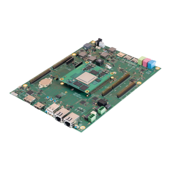
User's Manual l MBa8x UM 0100 l © 2021, TQ-Systems GmbH Page 44 Assembly Figure 30: MBa8x, component placement top... - Page 46 User's Manual l MBa8x UM 0100 l © 2021, TQ-Systems GmbH Page 45 Assembly (continued) Figure 31: MBa8x, component placement bottom The labels on the MBa8x revision 02xx show the following information: Table 31: Labels on MBa8x Label Content Serial number...
-
Page 47: Safety Requirements And Protective Regulations
As the MBa8x is a development platform, no explicit EMC tests were performed. During the development of the MBa8x the standard DIN EN 55022:2010 limit class A was taken into account. ESD protection is provided on most interfaces of the MBa8x. -
Page 48: Environment Protection
By environmentally friendly processes, production equipment and products, we contribute to the protection of our environment. To be able to reuse the MBa8x, it is produced in such a way (a modular construction) that it can be easily repaired and disassembled. The energy consumption of the MBa8x is minimised by suitable measures. -
Page 49: Appendix
User's Manual l MBa8x UM 0100 l © 2021, TQ-Systems GmbH Page 48 APPENDIX Acronyms and definitions The following acronyms and abbreviations are used in this document: Table 33: Acronyms Acronym Meaning Analog/Digital Converter ® Advanced RISC Machine BIOS Basic Input/Output System... - Page 50 User's Manual l MBa8x UM 0100 l © 2021, TQ-Systems GmbH Page 49 Acronyms and definitions (continued) Table 26: Acronyms (continued) Acronym Meaning On-The-Go Printed Circuit Board PCIe Peripheral Component Interconnect express PCMCIA People Can't Memorize Computer Industry Acronyms Pull-Down...
-
Page 51: References
User's Manual l MBa8x UM 0100 l © 2021, TQ-Systems GmbH Page 50 References Table 34: Further applicable documents Name Rev., Date Company i.MX 8DualX Industrial Applications Processors - Data Sheet 15 May 2020 i.MX 8QuadXPlus and 8DualXPlus Applications Processors - Data Sheet 15 May 2020 i.MX 8DualXPlus/8QuadXPlus Applications Processor Reference Manual... - Page 52 TQ-Systems GmbH Mühlstraße 2 l Gut Delling l 82229 Seefeld Info@TQ-Group TQ-Group...
Need help?
Do you have a question about the MBa8x and is the answer not in the manual?
Questions and answers