Table of Contents
Advertisement
Quick Links
Advertisement
Table of Contents

Related Manuals for TQ-Systems MBLS1028A


Summary of Contents for TQ-Systems MBLS1028A
- Page 1 MBLS1028A User's Manual MBLS1028A UM 0100 03.11.2020...
-
Page 2: Table Of Contents
User's Manual l MBLS1028A UM 0100 l © 2020, TQ-Systems GmbH Page i TABLE OF CONTENTS ABOUT THIS MANUAL ....................................1 Copyright and license expenses ................................1 Registered trademarks....................................1 Disclaimer ........................................1 Imprint ..........................................1 Tips on safety ........................................ 2 Symbols and typographic conventions ............................... - Page 3 User's Manual l MBLS1028A UM 0100 l © 2020, TQ-Systems GmbH Page ii TABLE OF CONTENTS (continued) SOFTWARE ........................................29 MECHANICS........................................ 30 TQMLS1028A and MBLS1028A dimensions ............................. 30 Notes of treatment....................................31 Embedding in the overall system ................................ 31 Housing ........................................31 Thermal management ....................................
- Page 4 User's Manual l MBLS1028A UM 0100 l © 2020, TQ-Systems GmbH Page iii TABLE DIRECTORY Table 1: Terms and Conventions .................................... 2 Table 2: Connectors assembled on MBLS1028A ..............................6 Table 3: Boot Mode configuration, DIP switch S9 ............................. 6 Table 4: C devices, address mapping on TQMLS1028A and MBLS1028A ....................
- Page 5 User's Manual l MBLS1028A UM 0100 l © 2020, TQ-Systems GmbH Page iv FIGURE DIRECTORY Figure 1: Block diagram MBLS1028A ..................................4 Figure 2: Block diagram TQMLS1028A ................................... 5 Figure 3: Block diagram clock generation on MBLS1028A ..........................7 Figure 4: Block diagram Reset structure ................................
-
Page 6: About This Manual
User's Manual, or due to usage of erroneous or incomplete information, are exempted, as long as there is no proven intentional or negligent fault of TQ-Systems GmbH. TQ-Systems GmbH explicitly reserves the rights to change or add to the contents of this User's Manual or parts of it without special notification. -
Page 7: Tips On Safety
Violation of this guideline may result in damage / destruction of the MBLS1028A and be dangerous to your health. -
Page 8: Naming Of Signals
User's Manual l MBLS1028A UM 0100 l © 2020, TQ-Systems GmbH Page 3 Naming of signals A hash mark (#) at the end of the signal name indicates a low-active signal. Example: RESET# If a signal can switch between two functions and if this is noted in the name of the signal, the low-active function is marked with a hash mark and shown at the end. -
Page 9: Brief Description
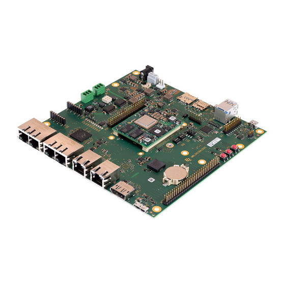
The MBLS1028A is designed as a carrier board for the TQMLS1028A. All TQMLS1028A interfaces, which can be used, are available on the MBLS1028A, thus the features of the CPU LS1028A can be evaluated and software development for a TQMLS1028A-based project can be started directly. -
Page 10: Electronics
EEPROM. All TQMLS1028A internal voltages are derived from the 5 V supply voltage. Further information can be found in the TQMLS1028A User’s Manual. The available signals are routed to the MBLS1028A via two connectors. On the MBLS1028A the interfaces provided by the TQMLS1028A are routed to industry standard connectors. Furthermore the MBLS1028A provides all power supplies and configurations required for the operation of the TQMLS1028A. -
Page 11: Tqmls1028A Pinout
The TQMLS1028A is held in the mating connectors on the TQMLS1028A by 240 pins with a retention force of approximately 24 N. To avoid damaging the connectors of the MBLS1028A or the TQMLS1028A while removing the TQMLS1028A, the use of the extraction tool MOZI8XX is strongly recommended. -
Page 12: Clock Generation
User's Manual l MBLS1028A UM 0100 l © 2020, TQ-Systems GmbH Page 7 4.1.2 Clock generation The following figure shows, which clocks are required on the TQMLS1028A and how they are generated. Figure 3: Block diagram clock generation on MBLS1028A... -
Page 13: Reset Structure
Reset structure The reset structure is designed in such a way that the TQMLS1028A and the Reset button on the MBLS1028A are the control center. This ensures that the Reset is enabled at the right time during power-up. Corresponding reset delays are handled by the TQMLS1028A. -
Page 14: I 2 C Devices
User's Manual l MBLS1028A UM 0100 l © 2020, TQ-Systems GmbH Page 9 4.1.4 C devices The TQMLS1028A provides various I C buses, of which only IIC5 and IIC6 are used on the MBLS1028A. The following block diagram shows the I C bus structure. Figure 5: Block diagram I... -
Page 15: Temperature Sensor
GPIO port expander To control several components on the MBLS1028A, a port expander PCA9538 with 8 ports and a port expander PCA9555 with 16 ports are assembled. Both port expanders are controlled via IIC6. The addresses of the port expanders can be changed by reassembling resistors. -
Page 16: Power Supply
Furthermore the design allows power sequencing of all voltage levels used. All voltages are powered up after the boot process of the TQMLS1028A. At the two headers X25 and X38 on the MBLS1028A 1.8 V, 3.3 V, 5 V and 12 V are available. Both connectors share the available total power of the individual voltage rails. -
Page 17: Communication Interfaces
4.3.1 Ethernet 4.3.1.1 RGMII The LS1028A provides an RGMII Ethernet controller (EC1 – port 1). On the MBLS1028A the interface provides a Gigabit Ethernet ® port. The PHY supports IEEE 802.3 10BASE-T, 100BASE-T, and 1000BASE-T. The 125 MHz reference clock for the MAC of the CPU is generated by a quartz oscillator. -
Page 18: Qsgmii
The TSN switch is not routed via the Ethernet controller but via SerDes and is implemented as QSGMII. The QSGMII interface includes PHY reset and interrupt signals. When looking at the MBLS1028A from outside, X8 is on the left, X9 is on the right. Figure 11: Block diagram Ethernet QSGMII The following table shows the pinout of the Ethernet connectors X8, and X9. -
Page 19: Usb 3.0 Hub
User's Manual l MBLS1028A UM 0100 l © 2020, TQ-Systems GmbH Page 14 4.3.2 USB 3.0 Hub The TI USB 3.0 Hub TUSB8041 connected to the USB 3.0 OTG port (USB2) of the TQMLS1028A provides four USB HOST ports. Two ports (USB Host1&2) are routed as USB 3.0 interfaces to a stacked connector (X10), the third port is routed as USB 2.0 interface to the mPCIe connector X12, the fourth port is routed as USB 2.0 interface to header X38. -
Page 20: Usb 3.0 Otg
The LS1028A has two USB3.0 controllers with integrated PHY. USB1 is used as OTG interface. A USB 3.0 Micro B connector is assembled on the MBLS1028A. In order to use the interface as Host/Device, a suitable adapter comes with the MBLS1028A. Figure 14: Block diagram USB The USB1 port of the TQMLS1028A provides a theoretical data rate of 5 Gbit/s. -
Page 21: Can
User's Manual l MBLS1028A UM 0100 l © 2020, TQ-Systems GmbH Page 16 4.3.4 Two ISO-11898 compliant CAN interfaces are provided on the MBLS1028A. The signals are each connected to a 3-pin connector. The interfaces are galvanically isolated, but not among each other. -
Page 22: Mini Pcie Plus Sim Card Socket
Mini PCIe plus SIM card socket The MBLS1028A provides a Mini PCIe slot with one PCIE lane (×1) for full-size cards (50.95 mm × 30 mm). Any standard compliant Mini PCIe card can be used. A SIM card holder is also provided. - Page 23 User's Manual l MBLS1028A UM 0100 l © 2020, TQ-Systems GmbH Page 18 4.3.5 Mini PCIe plus SIM card socket (continued) Table 14: Pinout Mini PCIe, X12 Remark Signal Signal Remark – PCIE_WAKE# V_3V3_MPCIE – – DGND – – V_1V5_MPCIE –...
-
Page 24: B-Key (Ssd Sata)
Transfer rates of 1.5 Gb/s (Gen I), 3 Gb/s (Gen II) and 6Gb/s (Gen III) are possible. An M.2 slot with B-coding is used on the MBLS1028A. The MBLS1028A supports M.2 sizes 2242, 2260 and 2280. The standard mounting is for type 2280. - Page 25 User's Manual l MBLS1028A UM 0100 l © 2020, TQ-Systems GmbH Page 20 4.3.6 M.2 B-Key (SSD SATA) (continued) Table 16: Pinout M.2 B-Key, X35 Remark Signal Signal Remark Assembly option: 10 kΩ Pull-Up M2_CONFIG3 – DGND V_3V3 – –...
-
Page 26: Mikrobus
The MBLS1028A provides a mikroBUS™ for system extensions. The I2C5 bus is used at the mikroBUS™. mikroBUS™ modules require 3.3 V and 5 V, which are provided by the MBLS1028A. PTC fuses limit the current load at 750 mA. SPI and UART interfaces are connected via a switch in order to use them on headers or to be able to disconnect the mikroBUS™. -
Page 27: Sd Card
For the modes with 1.8 V I/O voltage they are switched by software. When rebooting or resetting the MBLS1028A, the SD card remains at the last used I/O voltage because it does not have a separate reset signal. The SDHC controller, on the other hand, returns to... -
Page 28: Headers
Headers The MBLS1028A features a 40-pin and a 60-pin 100 mil header, which provide all unused signals and those which should be easy to access. 1.8 V, 3.3 V, 5 V, and 12 V are available at both headers. The maximum current load of all four voltage rails is 3 A each. - Page 29 User's Manual l MBLS1028A UM 0100 l © 2020, TQ-Systems GmbH Page 24 4.3.9 Headers (continued) Table 20: Pinout Header 2, X38 Level Group Signal Signal Group Level 12 V Power V_12V V_3V3 Power 3.3 V Power V_5V0_SW V_3V3 Power 3.3 V...
-
Page 30: User Interfaces
User's Manual l MBLS1028A UM 0100 l © 2020, TQ-Systems GmbH Page 25 User interfaces 4.4.1 Display port The LS1028A provides a GPU with an integrated LCD controller that supports DisplayPort 1.3 and eDP 1.4. DisplayPort is implemented on the MBLS1028A. -
Page 31: Status Leds
4.4.2 Status LEDs Two green LEDs (V55, V56) are provided on the MBLS1028A for tests. They are controlled by IO1_5 and IO1_6 of the 16-port C expander PCA9538, D69, see Table 5. The presence of all important supply voltages is indicated by green LEDs. They light up when the corresponding voltage is active and simplify developing with the MBLS1028A. -
Page 32: Diagnostic Interfaces
® The JTAG signals of the TQMLS1028A are routed to an OpenSDA microcontroller via level shifters. Between level shifter and MBLS1028A are tri-state buffers, which are switched by the firmware of the OpenSDA. ® ® The JTAG port of the microcontroller for the OpenSDA interface is routed to a 10-pin JTAG connector with standard ARM pinout. -
Page 33: Opensda / Daplink
Currently the implementation of OpenSDA for the LS1028A is not available. However, a circuit for an OpenSDA programmer is prepared on the MBLS1028A, but it is currently not supported. A USB Mini-B connector (X24) to connect to a PC is available. -
Page 34: Usb Debug
User's Manual l MBLS1028A UM 0100 l © 2020, TQ-Systems GmbH Page 29 4.5.3 USB Debug A debug interface is available via UART1 of the TQMLS1028A. The UART signals are routed to header X36 as well as to a UART to USB converter and routed to USB Micro AB connector X19. -
Page 35: Mechanics
The MBLS1028A has overall dimensions (length × width) of 170 × 170 mm The MBLS1028A has a maximum height of approximately 26.4 mm. The MBLS1028A has six 4.3 mm mounting holes for the housing, and four 3.2 mm mounting holes for a heat sink. The MBLS1028A weighs approximately 200 grams without TQMLS1028A. -
Page 36: Notes Of Treatment
The TQMLS1028A is held in its mating connectors with a retention force of approximately 24 N. To avoid damage caused by mechanical stress, the TQMLS1028A may only be extracted from the MBLS1028A by using the extraction tool MOZI8XX that can be obtained separately. -
Page 37: Assembly
User's Manual l MBLS1028A UM 0100 l © 2020, TQ-Systems GmbH Page 32 Assembly Figure 23: MBLS1028A component placement top The labels on the MBLS1028A revision 0100 show the following information: Table 28: Labels on MBLS1028A Label Text Serial number... - Page 38 User's Manual l MBLS1028A UM 0100 l © 2020, TQ-Systems GmbH Page 33 Assembly (continued) Figure 24: MBLS1028A component placement bottom...
-
Page 39: Safety Requirements And Protective Regulations
TQMLS1028A and thus malfunction, deterioration or destruction. Protection against external effects Protection class IP00 was defined for the MBLS1028A. There is no protection against foreign objects, touch or humidity. Reliability and service life No detailed MTBF calculation has been done for the MBLS1028A. -
Page 40: Environment Protection
By environmentally friendly processes, production equipment and products, we contribute to the protection of our environment. To be able to reuse the MBLS1028A, it is produced in such a way, that it can be easily repaired and disassembled. The energy consumption of this subassembly is minimised by suitable measures. -
Page 41: Appendix
User's Manual l MBLS1028A UM 0100 l © 2020, TQ-Systems GmbH Page 36 APPENDIX 10.1 Acronyms and definitions The following acronyms and abbreviations are used in this document: Table 30: Acronyms Acronym Meaning Alternating Current AHCI Advanced Host Controller Interface ®... - Page 42 User's Manual l MBLS1028A UM 0100 l © 2020, TQ-Systems GmbH Page 37 10.1 Acronyms and definitions (continued) Table 30: Acronyms (continued) Acronym Meaning Power Personal Computer Printed Circuit Board PCIe Peripheral Component Interconnect express PCMCIA People Can’t Memorize Computer Industry Acronyms...
-
Page 43: References
User's Manual l MBLS1028A UM 0100 l © 2020, TQ-Systems GmbH Page 38 10.2 References Table 31: Further applicable documents Name Rev., Date Company ® QorIQ LS1028A Data Sheet Rev. 0, 12/2019 ® QorIQ LS1028A Reference Manual Rev. 0, 12/2019 ®... - Page 44 TQ-Systems GmbH Mühlstraße 2 l Gut Delling l 82229 Seefeld Info@TQ-Group TQ-Group...
Need help?
Do you have a question about the MBLS1028A and is the answer not in the manual?
Questions and answers