
Related Manuals for Intellinet IPS-52GM04-10G-400W


Summary of Contents for Intellinet IPS-52GM04-10G-400W
- Page 1 48-Port Gigabit Ethernet PoE+ Layer2+ Managed Switch with Four 10G SFP+ Uplinks User Manual Model 561587 intellinetnetwork.com...
- Page 2 48-Port Gigabit Ethernet PoE+ Layer2+ Managed Switch with Four 10G SFP+ Uplinks User Manual Disclaimer The contents of this manual were based on existing production information. The content may be modified due to a product version upgrade or any other reason. We reserve the right to modify the user manual without any notice or hint.
-
Page 3: Table Of Contents
48-Port Gigabit Ethernet PoE+ Layer2+ Managed Switch with Four 10G SFP+ Uplinks User Manual TABLE OF CONTENTS PRODUCT INTRODUCTION ....................7 ......................... 8 RODUCT APPEARANCE ..........................8 OWER SUPPLY ..........................8 ENTILATION E ............................9 ..........................9 INDICATOR PREPARATION FOR INSTALLATION ..................10 ......................... - Page 4 48-Port Gigabit Ethernet PoE+ Layer2+ Managed Switch with Four 10G SFP+ Uplinks User Manual CONNECTING THE SWITCH ....................21 (NIC) ................21 ONNECT THE OMPUTER TO THE WITCH ................. 21 WITCH CONNECTIONS TO OWERED EVICES ....................22 OW TO OG INTO THE WITCH WEB CONFIGURATION GUIDE .....................
- Page 5 48-Port Gigabit Ethernet PoE+ Layer2+ Managed Switch with Four 10G SFP+ Uplinks User Manual 6.2.8.1 Intermediate Agent ........................63 6.2.8.2 Port ............................64 6.2.9 Bandwidth Control ......................65 6.2.10 Broadcast Storm Control ....................66 6.2.11 Mirroring ........................67 6.2.12 Link Aggregation ......................68 6.2.12.1 Link Aggregation status ......................
- Page 6 48-Port Gigabit Ethernet PoE+ Layer2+ Managed Switch with Four 10G SFP+ Uplinks User Manual 6.3.2.3 Logins ............................111 6.3.3 Diagnostic ........................112 6.3.4 Syslog .......................... 113 6.3.4.1 Syslog Setup..........................114 6.3.4.2 Syslog Server Setup ........................115 APPENDIX: CONNECTORS AND CONNECTION MEDIA ............117 1000BASE-T/100BASE-TX/10BASE-T P ................
-
Page 7: Product Introduction
1 Product Introduction The 48-Port Gigabit Ethernet PoE+ Layer2+ Managed Switch with Four 10G SFP+ Uplinks from Intellinet Network Solutions fully mixes high-performance, high safety, multi-service, and great usability, providing brand new technical characteristics and a total solution. Each port of this PoE Switch provides high bandwidth and can power compatible wireless APs, IP cameras and much more. -
Page 8: Product Appearance
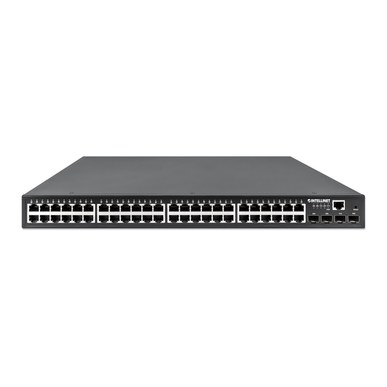
48-Port Gigabit Ethernet PoE+ Layer2+ Managed Switch with Four 10G SFP+ Uplinks User Manual 1.1 Product appearance The front panel of this PoE Switch consists of 48x10/100/1000 Mbps RJ45 ports, 4x1000/10000Mbps SFP+ ports, a Reset button, one console port and a series of LED indicators. The rear panel provides an AC power input interface and a grounding terminal. -
Page 9: Poe
48-Port Gigabit Ethernet PoE+ Layer2+ Managed Switch with Four 10G SFP+ Uplinks User Manual 1.4 PoE 48 x PoE ports compliant with IEEE802.3at/af standards. 1.5 LED indicator The LED indicators allow you to monitor, diagnose and troubleshoot any potential problem with the Switch, its connection or attached devices. -
Page 10: Preparation For Installation
48-Port Gigabit Ethernet PoE+ Layer2+ Managed Switch with Four 10G SFP+ Uplinks User Manual 2 Preparation for Installation 2.1 Safety Suggestions To avoid personal injury and equipment damage, please carefully read the safety suggestions before you install the Switch. ... -
Page 11: Fiber Use Safety
48-Port Gigabit Ethernet PoE+ Layer2+ Managed Switch with Four 10G SFP+ Uplinks User Manual 2.1.5 Fiber Use Safety Notes: When a fiber transceiver is in use, ensure that the port is connected with an optical fiber cable or is covered with a dust cap to keep out dust and avoid harm to your eyes. When the optical module is in use, do not pull out the fiber cable and stare into the transceiver interface or you may harm your eyes. -
Page 12: Emi
48-Port Gigabit Ethernet PoE+ Layer2+ Managed Switch with Four 10G SFP+ Uplinks User Manual Requirements for the Dust Content and Granularity in the Equipment Room Maximum diameter (μm) Maximum concentration 1.4×10 7×10 2.4×10 1.3×10 (Particle size / cubic meter) Apart from dust, the salt, acid and sulfide in the air in the equipment room must also meet strict requirements, as such poisonous substances may accelerate the corrosion of the metal and the aging of some parts. -
Page 13: Lightning Grounding
48-Port Gigabit Ethernet PoE+ Layer2+ Managed Switch with Four 10G SFP+ Uplinks User Manual 2.2.7 Lightning Grounding The lightning protection system of a facility is an independent system that consists of the lightning rod, downlead conductor and the connector to the grounding system, which usually shares the power reference ground and yellow/green safety cable ground. -
Page 14: Notes On Fiber Optic Connections
48-Port Gigabit Ethernet PoE+ Layer2+ Managed Switch with Four 10G SFP+ Uplinks User Manual of the switch must be deployed far away from the grounding device of the electrical equipment and anti-lightning grounding device. Keep the equipment away from a high-power radio transmitter, radar-transmitting station, and high-frequency large-current device. -
Page 15: Installing The Switch
48-Port Gigabit Ethernet PoE+ Layer2+ Managed Switch with Four 10G SFP+ Uplinks User Manual 3 Installing the Switch Ensure that you have carefully read the section of Preparation before Installation. Make sure that the requirements set forth in that section have been met. 3.1 Installation Overview Only professional technicians should install the equipment. -
Page 16: Confirmations - Pre-Installation
48-Port Gigabit Ethernet PoE+ Layer2+ Managed Switch with Four 10G SFP+ Uplinks User Manual 3.1.1 Confirmations — Pre-Installation Before installation, ensure the following points: Whether ventilation requirements are met for the switch Whether the requirements of temperature and humidity are met for the switch Whether power cables are already laid out and whether the requirements of electrical current are met Whether related network adaption lines are already laid out... -
Page 17: Desktop Installation
48-Port Gigabit Ethernet PoE+ Layer2+ Managed Switch with Four 10G SFP+ Uplinks User Manual b. Use the screws provided with the equipment rack to mount the Switch on the rack and fix it. 3.2.2 Desktop Installation Users can place the switch on a clean, dry, sturdy support structure such as a desk, table or bench that can fully support the weight of the switch and its connections: Ensure that the air around the switch is well ventilated. -
Page 18: Confirmations - Post-Installation
48-Port Gigabit Ethernet PoE+ Layer2+ Managed Switch with Four 10G SFP+ Uplinks User Manual 3.3.1 Confirmations — Post-Installation Before checking the installation, switch off the power supply to avoid any personal injury or damage to a component due to connection errors. Check that the ground line is connected. -
Page 19: Common Troubleshooting For Installation
48-Port Gigabit Ethernet PoE+ Layer2+ Managed Switch with Four 10G SFP+ Uplinks User Manual 4 Common Troubleshooting for Installation 4.1 General Installation Troubleshooting Overview... -
Page 20: Common Troubleshooting
48-Port Gigabit Ethernet PoE+ Layer2+ Managed Switch with Four 10G SFP+ Uplinks User Manual 4.2 Common Troubleshooting Symptom Possible Causes Solution The power supply module does not supply Check whether the power socket at The status indicator is power. the equipment room is normal and not on after the switch The power cable is in loose contact. -
Page 21: Connecting The Switch
48-Port Gigabit Ethernet PoE+ Layer2+ Managed Switch with Four 10G SFP+ Uplinks User Manual 5 Connecting the Switch 5.1 Connect the Computer (NIC) to the Switch Use standard Cat5/5e Ethernet cable (UTP/STP) to connect the Switch to end nodes as described below. -
Page 22: How To Log Into The Switch
48-Port Gigabit Ethernet PoE+ Layer2+ Managed Switch with Four 10G SFP+ Uplinks User Manual 5.3 How to Log into the Switch As the Switch provides a Web-based management login, you can configure your computer’s IP address manually to log on to the Switch. The default settings of the Switch are shown below. Parameter Default Value Default IP address... -
Page 23: Web Configuration Guide
48-Port Gigabit Ethernet PoE+ Layer2+ Managed Switch with Four 10G SFP+ Uplinks User Manual 6 Web Configuration Guide The configuration interface of the Switch consists of 3 main areas: the status bar at the top, the menu bar on the left, and the main configuration window in the middle of the screen. Select the different functions in the menu bar to modify settings in the main configuration window. -
Page 24: System Info
48-Port Gigabit Ethernet PoE+ Layer2+ Managed Switch with Four 10G SFP+ Uplinks User Manual 6.1.1 System Info Selecting Basic Setting>System Info in the navigation bar lets you view the basic information of System and configure the IP address and System name. 【P 】... -
Page 25: Vlan Interface Config
48-Port Gigabit Ethernet PoE+ Layer2+ Managed Switch with Four 10G SFP+ Uplinks User Manual Interface: You can select the way of interface, including vlan-interface and supervlan-interface. Vlan ID: Choose the Vlan ID. 6.1.1.2 Vlan Interface Config Set IP address as 192.168.2.1 and mask as 255.255.255.0, and then selecting override. Override: You can override or not override the original main IP address. -
Page 26: General Setup
48-Port Gigabit Ethernet PoE+ Layer2+ Managed Switch with Four 10G SFP+ Uplinks User Manual Destination IP Address: setting destination IP Address of Static Routing IP Subnet Mask: setting IP Subnet Mask Gateway IP Address: setting IP Address Setting System name as Switch 6.1.2 General Setup Selecting Basic Setting>General Setup in the navigation bar lets you view the basic information of Switch, Such as System description and so on. -
Page 27: Ip Setup
48-Port Gigabit Ethernet PoE+ Layer2+ Managed Switch with Four 10G SFP+ Uplinks User Manual 【C 】 ONFIGURATION EXAMPLE Setting System name as Switch. 6.1.3 IP Setup Selecting Basic Setting>IP Setup in the navigation bar lets you configure IP. 6.1.3.1 Vlan Interface Selecting Basic Setting>IP Setup>Vlan Interface in the navigation bar lets you configure Vlan interface. -
Page 28: Vlan Interface Config
48-Port Gigabit Ethernet PoE+ Layer2+ Managed Switch with Four 10G SFP+ Uplinks User Manual 【P 】 ARAMETER ESCRIPTION Parameter Description Selecting the interface: Interface vlan-interface Supervlan-interface Vlan ID You can specify the vlan ID Name The name of interface 6.1.3.2 Vlan Interface Config Selecting Basic Setting>IP Setup>Vlan interface Config in the navigation bar lets you configure Vlan Interface Config. -
Page 29: Vlan Interface
48-Port Gigabit Ethernet PoE+ Layer2+ Managed Switch with Four 10G SFP+ Uplinks User Manual 【P 】 ARAMETER ESCRIPTION Parameter Description Interface name Name of interface Vlan ID You can specify the vlan ID IP Address User login in Switch using the IP Address Override You can override formeroriginal primary IP or not 【C... -
Page 30: Vlan Interface Config
48-Port Gigabit Ethernet PoE+ Layer2+ Managed Switch with Four 10G SFP+ Uplinks User Manual 6.1.3.4 Vlan Interface Config Setting IP address as 192.168.2.1 and mask as 255.255.255.0, and then selecting override. -
Page 31: Static Routing
48-Port Gigabit Ethernet PoE+ Layer2+ Managed Switch with Four 10G SFP+ Uplinks User Manual 6.1.3.5 Static Routing Selecting Basic Setting>IP Setup>Static Routing in the navigation bar lets you specify some routing manually. 【P 】 ARAMETER ESCRIPTION Parameter Description Destination IP Address Setting destination IP Address of Static Routing. -
Page 32: Port Setup
48-Port Gigabit Ethernet PoE+ Layer2+ Managed Switch with Four 10G SFP+ Uplinks User Manual 6.1.4 Port Setup Selecting Basic Setting>Port Setup in the navigation bar lets you configure the related parameters of a port. - Page 33 48-Port Gigabit Ethernet PoE+ Layer2+ Managed Switch with Four 10G SFP+ Uplinks User Manual 【P 】 ARAMETER ESCRIPTION Parameter Description Port number Port Choose whether to close link port status Status: link Down Set port priority, the range of 0-7 priority Choose the following modes: Set speed...
-
Page 34: Dhcp Server
48-Port Gigabit Ethernet PoE+ Layer2+ Managed Switch with Four 10G SFP+ Uplinks User Manual 6.1.5 DHCP Server Selecting Basic Setting>DHCP Server in the navigation bar lets you configure a DHCP server pool and DHCP server group. 6.1.5.1 DHCP server pool set Selecting Basic Setting>DHCP server>DHCP server pool set in the navigation bar lets you configure a DHCP Server pool set. -
Page 35: Dhcp Server Group Set
48-Port Gigabit Ethernet PoE+ Layer2+ Managed Switch with Four 10G SFP+ Uplinks User Manual 【P 】 ARAMETER ESCRIPTION Parameter Description ip pool ip pool ID name Set the name of ip pool hire time Set hire time Gate Address Set Gate Address Ip Mask Set Ip Mask First DNS... -
Page 36: Dhcp-Relay
48-Port Gigabit Ethernet PoE+ Layer2+ Managed Switch with Four 10G SFP+ Uplinks User Manual 6.1.6 DHCP-Relay Selecting Basic Setting>DHCP-Relay in the navigation bar lets you turn on the DHCP relay function, Hidden DHCP Server. Set the source IP used. 6.1.7 Stacking Selecting Basic Setting>Stacking in the navigation bar lets you view the stack interface information, neighbor interface information, start the stack function and set system priority. -
Page 37: Stacking Configuration
48-Port Gigabit Ethernet PoE+ Layer2+ Managed Switch with Four 10G SFP+ Uplinks User Manual 【P 】 ARAMETER ESCRIPTION Parameter Description Each device in the system must manually specify an unrepeatable Slot ID number, unique identity Two different working modes: Single-machine mode: this mode is the same as the general switch, Status does not to provide stack function. - Page 38 48-Port Gigabit Ethernet PoE+ Layer2+ Managed Switch with Four 10G SFP+ Uplinks User Manual 【P 】 ARAMETER ESCRIPTION Parameter Description Active Select open or close stack System Priority Set system priority, the default is 0 Slot id Freeze Freeze slot ID Slot id After Reboot Device number after the device is rebooted Note:...
-
Page 39: Advanced Application
The switch drops tagged VLAN packets that arrive at the access port. c. As far as the Intellinet Network Solutions switch is concerned, any port that isn’t defined as a trunk or hybrid port is considered an access port. - Page 40 48-Port Gigabit Ethernet PoE+ Layer2+ Managed Switch with Four 10G SFP+ Uplinks User Manual 2. Trunk Ports (tagged) a. Trunk ports are designed to filter out packets that have either no VLAN tag or VLAN tags that are not on the allowed VLAN ID list. b.
-
Page 41: Vlan Status
48-Port Gigabit Ethernet PoE+ Layer2+ Managed Switch with Four 10G SFP+ Uplinks User Manual 6.2.1.1 VLAN Status Selecting Advanced Application>VLAN>VLAN Status in the navigation bar lets you view VLAN status. 【P 】 ARAMETER ESCRIPTION Parameter Description VLAN Status View all VLANs configured in the device VLAN Search by VID Enter VID to view the specified VLAN 【C... -
Page 42: Vlan Port Settings
48-Port Gigabit Ethernet PoE+ Layer2+ Managed Switch with Four 10G SFP+ Uplinks User Manual 6.2.1.2 VLAN Port Settings Selecting Advanced Application>VLAN>VLAN Port Settings in the navigation bar lets you set VLAN ports. - Page 43 48-Port Gigabit Ethernet PoE+ Layer2+ Managed Switch with Four 10G SFP+ Uplinks User Manual 【P 】 ARAMETER ESCRIPTION Parameter Description PVID The PVID of the port can be modified, the default port PVID is 1 Choose the following kinds: Acceptable Frame Tagged only Untagged only Choose the following modes:...
-
Page 44: Static Vlan
48-Port Gigabit Ethernet PoE+ Layer2+ Managed Switch with Four 10G SFP+ Uplinks User Manual 6.2.1.3 Static VLAN Selecting Advanced Application>Static VLAN in the navigation bar lets you configure a Static VLAN. 【P 】 ARAMETER ESCRIPTION Parameter Description VLAN Group ID VLAN Group ID Name VLAN Group name... - Page 45 48-Port Gigabit Ethernet PoE+ Layer2+ Managed Switch with Four 10G SFP+ Uplinks User Manual 【C 】 ONFIGURATION EXAMPLE Add and delete VLAN members Adding a new VLAN, VLAN Group ID 120 contains untag member ports 6 and 8 and tag member ports 18 and 20.
-
Page 46: Mac Address Forwarding
48-Port Gigabit Ethernet PoE+ Layer2+ Managed Switch with Four 10G SFP+ Uplinks User Manual 6.2.2 MAC Address Forwarding Selecting Advanced Application>MAC Address Forwarding in the navigation bar lets you configure MAC Address Forwarding. 【P 】 ARAMETER ESCRIPTION Parameter Description MAC Type: Static MAC MAC Type Dynamic MAC... -
Page 47: Spanning Tree Protocol
48-Port Gigabit Ethernet PoE+ Layer2+ Managed Switch with Four 10G SFP+ Uplinks User Manual 2. Unknown source mac packet drop settings. 6.2.3 Spanning Tree Protocol Selecting Advanced Application>Spanning Tree Protocol in the navigation bar lets you configure spanning tree protocol. -
Page 48: Spanning Tree Protocol Status
48-Port Gigabit Ethernet PoE+ Layer2+ Managed Switch with Four 10G SFP+ Uplinks User Manual 6.2.3.1 Spanning Tree Protocol Status Selecting Advanced Application>Spanning Tree Protocol>Spanning Tree Protocol status in the navigation bar lets you view spanning tree protocol status. 【P 】 ARAMETER ESCRIPTION Parameter... -
Page 49: Spanning Tree Configuration
48-Port Gigabit Ethernet PoE+ Layer2+ Managed Switch with Four 10G SFP+ Uplinks User Manual 6.2.3.2 Spanning Tree Configuration Selecting Advanced Application>Spanning Tree Protocol>Spanning Tree configuration in the navigation bar lets you configure spanning tree. 【P 】 ARAMETER ESCRIPTION Parameter Description Spanning tree mode: IEEE Compatible Spanning Tree Spanning Tree Mode... -
Page 50: Compatible/Rapid Spanning Tree Protocol
48-Port Gigabit Ethernet PoE+ Layer2+ Managed Switch with Four 10G SFP+ Uplinks User Manual 6.2.3.3 Compatible/Rapid Spanning Tree Protocol Selecting Advanced Application>Spanning Tree Protocol>Compatible/Rapid Spanning Tree Protocol in the navigation bar lets you configure Compatible/Rapid Spanning Tree Protocol. - Page 51 48-Port Gigabit Ethernet PoE+ Layer2+ Managed Switch with Four 10G SFP+ Uplinks User Manual 【P 】 ARAMETER ESCRIPTION Parameter Description Bridge Priority Set bridge priority, the default instance bridge priority for 32768 Hello Time Switches sends bpdu in packet interval Ports that have not yet received a message in the time will initiate Max Age topology changes...
-
Page 52: Multiple Spanning Tree Protocol
48-Port Gigabit Ethernet PoE+ Layer2+ Managed Switch with Four 10G SFP+ Uplinks User Manual 6.2.3.4 Multiple Spanning Tree Protocol Selecting Advanced Application>Spanning Tree Protocol>Multiple Spanning Tree Protocol in the navigation bar lets you configure Multiple Spanning Tree Protocol. - Page 53 48-Port Gigabit Ethernet PoE+ Layer2+ Managed Switch with Four 10G SFP+ Uplinks User Manual 【P 】 ARAMETER ESCRIPTION Parameter Description Hello Time Switches sends bpdu in packet interval Ports that have not yet received a message in time will initiate Max age topology changes Forwarding Delay...
-
Page 54: Erps Protocol
48-Port Gigabit Ethernet PoE+ Layer2+ Managed Switch with Four 10G SFP+ Uplinks User Manual 2. Instance 3. The priority of port 24 is 64, and the path cost is 20000. 6.2.4 ERPS Protocol Selecting Advanced Application>ERPS Protocol in the navigation bar lets you configure ERPS protocol. - Page 55 48-Port Gigabit Ethernet PoE+ Layer2+ Managed Switch with Four 10G SFP+ Uplinks User Manual 【P 】 ARAMETER ESCRIPTION Parameter Description Global ERPS status Select open or close ERPS Instance The range of 0 – 15, active instance. Meg level The range of 0 – 7 Ring Id The range of 1 –...
-
Page 56: Eaps Protocol
48-Port Gigabit Ethernet PoE+ Layer2+ Managed Switch with Four 10G SFP+ Uplinks User Manual 6.2.5 EAPS Protocol Selecting Advanced Application>EAPS Protocol in the navigation bar lets you configure EAPS protocol. 6.2.5.1 Ethernet Automatic Protection Switching Selecting Advanced Application>EAPS Protocol>Ethernet automatic protection switching in the navigation bar lets you configure Ethernet automatic protection switching. - Page 57 48-Port Gigabit Ethernet PoE+ Layer2+ Managed Switch with Four 10G SFP+ Uplinks User Manual 【P 】 ARAMETER ESCRIPTION Parameter Description Active Select open or close EAPS Hello time Switches sends bpdu in packet interval Fail Timer Configure the information timeout Major Fault The Major Fault timer will be automatically updated by the system Pre Forward...
-
Page 58: Eaps Domain
48-Port Gigabit Ethernet PoE+ Layer2+ Managed Switch with Four 10G SFP+ Uplinks User Manual 2. Domain 6.2.5.2 EAPS Domain Selecting Advanced Application>EAPS Protocol>EAPS Domain in the navigation bar lets you configure EAPS Domain. - Page 59 48-Port Gigabit Ethernet PoE+ Layer2+ Managed Switch with Four 10G SFP+ Uplinks User Manual 【P 】 ARAMETER ESCRIPTION Parameter Description Domain ID Select Domain ID Control VLAN You must configure the VLAN before configuring the EAPS Ring Work mode: standard Work mode huawei eips-subring...
-
Page 60: Vrrp Protocol
48-Port Gigabit Ethernet PoE+ Layer2+ Managed Switch with Four 10G SFP+ Uplinks User Manual 2. Configure Ring 6.2.6 VRRP Protocol Selecting Advanced Application>VRRP Protocol in the navigation bar lets you configure the VRRP Protocol. -
Page 61: Layer 2 Tunneling Protocol
48-Port Gigabit Ethernet PoE+ Layer2+ Managed Switch with Four 10G SFP+ Uplinks User Manual 【P 】 ARAMETER ESCRIPTION Parameter Description VRRP ID list You select VRRP ID VRRP ID VRRP ID Interface name Specify VLAN virtual ip Set virtual IP preempt Enable or disable preempt priority... -
Page 62: Pppoe Ia
48-Port Gigabit Ethernet PoE+ Layer2+ Managed Switch with Four 10G SFP+ Uplinks User Manual 【C 】 ONFIGURATION EXAMPLE 6.2.8 PPPoE IA Selecting Advanced Application>PPPoE IA in the navigation bar lets you configure PPPoE IA. -
Page 63: Intermediate Agent
48-Port Gigabit Ethernet PoE+ Layer2+ Managed Switch with Four 10G SFP+ Uplinks User Manual 6.2.8.1 Intermediate Agent Selecting Advanced Application>PPPoE IA>Intermediate Agent in the navigation bar lets you configure an Intermediate Agent. 【P 】 ARAMETER ESCRIPTION Parameter Description delimiter Configure delimiter, choose space, : , ., #, / format Configure format, choose binary, ascii type... -
Page 64: Port
48-Port Gigabit Ethernet PoE+ Layer2+ Managed Switch with Four 10G SFP+ Uplinks User Manual 6.2.8.2 Port Selecting Advanced Application>PPPoE IA>Port in the navigation bar lets you configure ports. 【P 】 ARAMETER ESCRIPTION Parameter Description active Select open or close port PPPoEIA Server Trusted State Configure the upstream port to be Trusted or Untrusted Drop... -
Page 65: Bandwidth Control
48-Port Gigabit Ethernet PoE+ Layer2+ Managed Switch with Four 10G SFP+ Uplinks User Manual 6.2.9 Bandwidth Control Selecting Advanced Application>Bandwidth Control in the navigation bar lets you configure Bandwidth Control. 【I 】 NSTRUCTIONS 1 Mbit/s = 1000 Kbit/s = 1000 / 8 KB/s = 125 KB/s. That is, the theoretical rate of 1M bandwidth is 125 KB/s. -
Page 66: Broadcast Storm Control
48-Port Gigabit Ethernet PoE+ Layer2+ Managed Switch with Four 10G SFP+ Uplinks User Manual 6.2.10 Broadcast Storm Control Selecting Advanced Application>Broadcast Storm Control in the navigation bar lets you configure Broadcast Storm Control. 【P 】 ARAMETER ESCRIPTION Parameter Description Broadcast rate limitation (the range of: 64-32000000, unit: pps, you Broadcast must enter multiple of 64, default to 49984) Multicast rate limitation (the range of: 64-32000000, unit: pps, you... -
Page 67: Mirroring
48-Port Gigabit Ethernet PoE+ Layer2+ Managed Switch with Four 10G SFP+ Uplinks User Manual 6.2.11 Mirroring Selecting Advanced Application>Mirroring in the navigation bar lets you configure mirroring. 【P 】 ARAMETER ESCRIPTION Parameter Description Active Select open or close Mirroring Set up the monitoring port and forward the flow data of the source Monitor Port port to the message analyzer to analyze the message and then forward to the monitoring port... -
Page 68: Link Aggregation
48-Port Gigabit Ethernet PoE+ Layer2+ Managed Switch with Four 10G SFP+ Uplinks User Manual 【C 】 ONFIGURATION EXAMPLE Open mirroring, configure monitoring port is port 8, the source port is port 7, and the mirror message is in both directions. 6.2.12 Link Aggregation Selecting Advanced Application>Link Aggregation in the navigation bar lets you configure link aggregation. -
Page 69: Link Aggregation Status
48-Port Gigabit Ethernet PoE+ Layer2+ Managed Switch with Four 10G SFP+ Uplinks User Manual 6.2.12.1 Link Aggregation status Selecting Advanced Application>Link Aggregation>Link Aggregation Status in the navigation bar lets you view link aggregation status. You can view Group ID, Enabled Ports, Synchronized Ports, Aggregator ID, Criteria, Status. -
Page 70: Link Aggregation Setting
48-Port Gigabit Ethernet PoE+ Layer2+ Managed Switch with Four 10G SFP+ Uplinks User Manual 6.2.12.2 Link Aggregation Setting Selecting Advanced Application>Link Aggregation>Link Aggregation Setting in the navigation bar lets you set Link Aggregation. 【P 】 ARAMETER ESCRIPTION Parameter Description Group ID Add the port to the specified Aggregation Group ID LACP mode Configure port aggregation(static/active/passive) -
Page 71: Link Aggregation Control Protocol
48-Port Gigabit Ethernet PoE+ Layer2+ Managed Switch with Four 10G SFP+ Uplinks User Manual 【C 】 ONFIGURATION EXAMPLE Configure parameters of Aggregation Group port 8. 6.2.12.3 Link Aggregation Control Protocol Selecting Advanced Application>Link Aggregation>Link Aggregation Control Protocol in the navigation bar lets you configure Link Aggregation Control Protocol. 【P 】... -
Page 72: Port Security
48-Port Gigabit Ethernet PoE+ Layer2+ Managed Switch with Four 10G SFP+ Uplinks User Manual 【C 】 ONFIGURATION EXAMPLE 1. Open aggregation group T1 LACP. 2. The priority for configuring port 8 is 64. 6.2.13 Port Security Selecting Advanced Application>Port Security in the navigation bar lets you configure port address learn control. - Page 73 48-Port Gigabit Ethernet PoE+ Layer2+ Managed Switch with Four 10G SFP+ Uplinks User Manual 【P 】 ARAMETER ESCRIPTION Parameter Description Age-Enable Open age-enable Age-Time Set Age Time (the range of 10 – 1000000, unit: second) Max Mac Limit Number Set the global Max MAC Limit Number (0 – 16384) (Global) The MAC address learning function of port enables the power Address Learning...
-
Page 74: Poe Settings
48-Port Gigabit Ethernet PoE+ Layer2+ Managed Switch with Four 10G SFP+ Uplinks User Manual 5. Configure Address Learn Vlan Control, set Max Mac Limit Number (Vlan) to 1900. 6.2.14 PoE Settings Selecting Advanced Application>PoE Settings in the navigation bar lets you configure PoE. Only PoE devices have this function. - Page 75 48-Port Gigabit Ethernet PoE+ Layer2+ Managed Switch with Four 10G SFP+ Uplinks User Manual 【P 】 ARAMETER ESCRIPTION Parameter Description Power limit (1 – 400) The power of switch PoE can be limited...
-
Page 76: Poe Port Settings
48-Port Gigabit Ethernet PoE+ Layer2+ Managed Switch with Four 10G SFP+ Uplinks User Manual 【C 】 ONFIGURATION EXAMPLE Set power limit to 390 W. 6.2.14.2 PoE Port Settings Selecting Advanced Application>PoE Settings>PoE Port Settings in the navigation bar lets you configure PoE ports. -
Page 77: Classifier
48-Port Gigabit Ethernet PoE+ Layer2+ Managed Switch with Four 10G SFP+ Uplinks User Manual Priority Configure port Priority: low, critical, high; the default priority is low Power limit The power of switch PoE can be limited 【C 】 ONFIGURATION EXAMPLE Configure the PoE for port 1. - Page 78 48-Port Gigabit Ethernet PoE+ Layer2+ Managed Switch with Four 10G SFP+ Uplinks User Manual 【C 】 ONFIGURATION EXAMPLE...
-
Page 79: Policy Rule
48-Port Gigabit Ethernet PoE+ Layer2+ Managed Switch with Four 10G SFP+ Uplinks User Manual 6.2.16 Policy Rule Selecting Advanced Application>Policy Rule in the navigation bar lets you configure Policy Rules. 【P 】 ARAMETER ESCRIPTION Parameter Description Active Active Policy Rule Classifier(s) You need to match the set of classification rules Set Bandwidth, Egress Port, Priority, DSCP, TOS... -
Page 80: Queuing Method
48-Port Gigabit Ethernet PoE+ Layer2+ Managed Switch with Four 10G SFP+ Uplinks User Manual 6.2.17 Queuing Method Selecting Advanced Application>Queuing Method in the navigation bar lets you configure a queuing method. 【P 】 ARAMETER ESCRIPTION Parameter Description Five methods: Method SPQ, WRR, SP+WRR, WFQ, SP+WFQ 【C 】... -
Page 81: Multicast
48-Port Gigabit Ethernet PoE+ Layer2+ Managed Switch with Four 10G SFP+ Uplinks User Manual 6.2.18 Multicast Selecting Advanced Application>Multicast in the navigation bar lets you configure Multicast. 6.2.18.1 Multicast Status Selecting Advanced Application>Multicast>Multicast Status in the navigation bar lets you view all multicast settings. -
Page 82: Multicast Settings
48-Port Gigabit Ethernet PoE+ Layer2+ Managed Switch with Four 10G SFP+ Uplinks User Manual 6.2.18.2 Multicast Settings Selecting Advanced Application>Multicast>Multicast Settings in the navigation bar lets you configure multicast settings. -
Page 83: Igmp Snooping Deny Vlan
48-Port Gigabit Ethernet PoE+ Layer2+ Managed Switch with Four 10G SFP+ Uplinks User Manual 【P 】 ARAMETER ESCRIPTION Parameter Description Active Open IGMP-snooping Querier Open IGMP-snooping timed query function Host Timeout Configure the dynamic group sowing time (default is 300s) IGMP Route Port Open IGMP Route Port Forward Forward... -
Page 84: Igmp Filtering Profile
48-Port Gigabit Ethernet PoE+ Layer2+ Managed Switch with Four 10G SFP+ Uplinks User Manual 【P 】 ARAMETER ESCRIPTION Parameter Description VLAN’s ID 6.2.18.4 IGMP Filtering Profile Selecting Advanced Application>Multicast>IGMP Filtering Profile in the navigation bar lets you add and remove the preview feature of the modified group. -
Page 85: Ipv6 Multicast
48-Port Gigabit Ethernet PoE+ Layer2+ Managed Switch with Four 10G SFP+ Uplinks User Manual 【P 】 ARAMETER ESCRIPTION Parameter Description Profile ID The range of 1 – 128 Profile Limit Profile rules can be permit or deny Input Format The preview address can be configured to be either IP or MAC 6.2.19 IPv6 Multicast Selecting Advanced Application>IPv6 Multicast in the navigation bar lets you configure IPv6 Multicast. -
Page 86: Ipv6 Multicast Setting
48-Port Gigabit Ethernet PoE+ Layer2+ Managed Switch with Four 10G SFP+ Uplinks User Manual 6.2.19.2 IPv6 Multicast Setting Selecting Advanced Application>IPv6 Multicast>IPv6 Multicast Setting in the navigation bar lets you configure IPv6 Multicast. - Page 87 48-Port Gigabit Ethernet PoE+ Layer2+ Managed Switch with Four 10G SFP+ Uplinks User Manual 【P 】 ARAMETER ESCRIPTION Parameter Description Active Enable or disable MLD snooping Querier Enable or disable MLD snooping timed querier Host Timeout Configure Dynamic IPv6 multicast aging time (default is 300s) MLD Route Port Forward Enable or disable MLD Route Port Forward Configure maximum learning IPv6 Multicast message...
-
Page 88: Mld Snooping Deny Vlan
48-Port Gigabit Ethernet PoE+ Layer2+ Managed Switch with Four 10G SFP+ Uplinks User Manual 6.2.19.3 MLD Snooping Deny VLAN Selecting Advanced Application>IPv6 Multicast>MLD Snooping Deny VLAN in the navigation bar lets you configure MLD Snooping Deny VLAN. 【P 】 ARAMETER ESCRIPTION Parameter Description... -
Page 89: Dos Attack Protect
48-Port Gigabit Ethernet PoE+ Layer2+ Managed Switch with Four 10G SFP+ Uplinks User Manual 6.2.20 DoS Attack Protect Selecting Advanced Application>DoS attack protect in the navigation bar lets you configure DoS Attack Protect. - Page 90 48-Port Gigabit Ethernet PoE+ Layer2+ Managed Switch with Four 10G SFP+ Uplinks User Manual 【P 】 ARAMETER ESCRIPTION Parameter Description The CPU queue is controlled by setting minimum bandwidth and cpu queue control maximum bandwidth (minimum value is 64 kbps) The DOS attack is controlled by the discarding behavior of the dos attack control corresponding message...
- Page 91 48-Port Gigabit Ethernet PoE+ Layer2+ Managed Switch with Four 10G SFP+ Uplinks User Manual 2. DoS attack control...
-
Page 92: Dhcp Snooping Setting
48-Port Gigabit Ethernet PoE+ Layer2+ Managed Switch with Four 10G SFP+ Uplinks User Manual 6.2.21 DHCP Snooping Setting Selecting Advanced Application>DHCP Snooping Setting in the navigation bar lets you configure DHCP Snooping. -
Page 93: Dhcp Snooping Setting
48-Port Gigabit Ethernet PoE+ Layer2+ Managed Switch with Four 10G SFP+ Uplinks User Manual 6.2.21.1 DHCP Snooping Setting Selecting Advanced Application>DHCP Snooping Setting>DHCP Snooping Setting in the navigation bar lets you configure DHCP Snooping Settings. 【P 】 ARAMETER ESCRIPTION Parameter Description DHCP Snooping Enable Enable or disable DHCP Snooping... -
Page 94: Ip Source Guard
48-Port Gigabit Ethernet PoE+ Layer2+ Managed Switch with Four 10G SFP+ Uplinks User Manual 6.2.21.2 IP Source Guard Selecting Advanced Application>DHCP Snooping Setting>IP Source Guard in the navigation bar lets you configure IP Source Guard. 【P 】 ARAMETER ESCRIPTION Parameter Description Disable unbinding entry to access Enable or disable unbinding entry to access the... -
Page 95: Sntp Setting
48-Port Gigabit Ethernet PoE+ Layer2+ Managed Switch with Four 10G SFP+ Uplinks User Manual 6.2.22 SNTP Setting Selecting Advanced Application>SNTP Setting in the navigation bar lets you configure SNTP. - Page 96 48-Port Gigabit Ethernet PoE+ Layer2+ Managed Switch with Four 10G SFP+ Uplinks User Manual 【P 】 ARAMETER ESCRIPTION Parameter Description SNTP Client Enable Enable or disable SNTP Client SNTP Client Mode: broadcast SNTP Client Mode anycast multicast unicast The interval the SNTP Client sends requests to SNTP SNTP Client Poll Interval Server If SNTP Client does not receive a response within a...
-
Page 97: Qinq
48-Port Gigabit Ethernet PoE+ Layer2+ Managed Switch with Four 10G SFP+ Uplinks User Manual 【C 】 ONFIGURATION XAMPLE 6.2.23 QinQ Selecting Advanced Application>QinQ in the navigation bar lets you configure QinQ. -
Page 98: Set Up Qinq
48-Port Gigabit Ethernet PoE+ Layer2+ Managed Switch with Four 10G SFP+ Uplinks User Manual 6.2.23.1 Set Up QinQ Selecting Advanced Application>QinQ>Set up QinQ in the navigation bar lets you Set up QinQ. 【P 】 ARAMETER ESCRIPTION Parameter Description Active Enable or disable global QinQ QinQ Enable or disable QinQ of ports Port Mode:... -
Page 99: Flexible Qinq
48-Port Gigabit Ethernet PoE+ Layer2+ Managed Switch with Four 10G SFP+ Uplinks User Manual 【C 】 ONFIGURATION XAMPLE 6.2.23.2 Flexible QinQ Selecting Advanced Application>QinQ>Flexible QinQ in the navigation bar lets you configure Flexible QinQ. -
Page 100: Aaa
48-Port Gigabit Ethernet PoE+ Layer2+ Managed Switch with Four 10G SFP+ Uplinks User Manual 【C 】 ONFIGURATION XAMPLE 6.2.24 AAA Selecting Advanced Application>AAA in the navigation bar lets you configure AAA. -
Page 101: 101
48-Port Gigabit Ethernet PoE+ Layer2+ Managed Switch with Four 10G SFP+ Uplinks User Manual 6.2.24.1 802.1x Selecting Advanced Application>AAA>802.1x in the navigation bar lets you configure 802.1x. - Page 102 48-Port Gigabit Ethernet PoE+ Layer2+ Managed Switch with Four 10G SFP+ Uplinks User Manual 【P 】 ARAMETER ESCRIPTION Parameter Description EAP Forwarding Mode: EAP Forwarding Mode eap-finish, Eap-tansfer If the same user fails to log in more than the allowed Quiet Period value, he or she will not be allowed to try to log in for a certain time...
-
Page 103: Radius Domain
48-Port Gigabit Ethernet PoE+ Layer2+ Managed Switch with Four 10G SFP+ Uplinks User Manual 6.2.24.2 Radius Domain Selecting Advanced Application>AAA>Radius Domain in the navigation bar lets you configure Radius Domain. 【P 】 ARAMETER ESCRIPTION Parameter Description Active Enable or disable radius domain Set domain name Domain Name Radius Server Name... -
Page 104: Remote Authentication
48-Port Gigabit Ethernet PoE+ Layer2+ Managed Switch with Four 10G SFP+ Uplinks User Manual 6.2.24.3 Remote Authentication Selecting Advanced Application>AAA>Remote Authentication in the navigation bar lets you configure Remote Authentication. 【P 】 ARAMETER ESCRIPTION Parameter Description Authenication Mode: Local, Authenication Mode Radius, Tacacs+ 6.2.24.4 TACACS+ Server Setup... -
Page 105: Radius Server Setup
48-Port Gigabit Ethernet PoE+ Layer2+ Managed Switch with Four 10G SFP+ Uplinks User Manual 【P 】 ARAMETER ESCRIPTION Parameter Description Authenication Mode: ascii, Authenication Type Chap, The time range of Preemption Time: Preemption Time 0 – 1440 minutes 6.2.24.5 Radius Server Setup Selecting Advanced Application>AAA>Radius Server Setup in the navigation bar lets you configure Radius Server Setup. -
Page 106: Management
48-Port Gigabit Ethernet PoE+ Layer2+ Managed Switch with Four 10G SFP+ Uplinks User Manual 【P 】 ARAMETER ESCRIPTION Parameter Description After this function is turned on, if the user authentication is 8021P Priority pass, it will modify the PVID of the user's port. In this feature, you can configure the version information of H3C Cams transmitting clients to the RADIUS server through the... -
Page 107: Access Control
48-Port Gigabit Ethernet PoE+ Layer2+ Managed Switch with Four 10G SFP+ Uplinks User Manual 【C 】 ONFIGURATION XAMPLE 1. Firmware Upgrade When you have downloaded the firmware, go to the Firmware Upgrade menu, and select the file on your computer using the Host File Path button. Then click Open to begin the upload. -
Page 108: Snmp
48-Port Gigabit Ethernet PoE+ Layer2+ Managed Switch with Four 10G SFP+ Uplinks User Manual 6.3.2.1 SNMP Selecting Management> Access Control>SNMP in the navigation bar lets you configure SNMP. 【P 】 ARAMETER ESCRIPTION Parameter Description Community string; equal to the NMS and Snmp agent Community Name communication between the password Read-only: specify the NMS (Snmp host) of MIB variables can only... -
Page 109: User Information
48-Port Gigabit Ethernet PoE+ Layer2+ Managed Switch with Four 10G SFP+ Uplinks User Manual 【C 】 ONFIGURATION XAMPLE Add a group name public community, access to Read-Write. Set host 192.168.1.100 to receive trap messages. The specified version is v2c. 6.3.2.2 User Information Selecting Management>... - Page 110 48-Port Gigabit Ethernet PoE+ Layer2+ Managed Switch with Four 10G SFP+ Uplinks User Manual 【P 】 ARAMETER ESCRIPTION Parameter Description Snmp username Username noauth Security Level auth Authentication DES Privacy Privacy User group name Group Encrypted password Password 【C 】 ONFIGURATION XAMPLE Add group initial;...
-
Page 111: Logins
48-Port Gigabit Ethernet PoE+ Layer2+ Managed Switch with Four 10G SFP+ Uplinks User Manual 6.3.2.3 Logins Selecting Management>Access Control>Logins in the navigation bar lets you modify the admin password and configure ordinary users. 【P 】 ARAMETER ESCRIPTION Parameter Description 0-1: Normal 2-15: administrator User privilege 【C 】... -
Page 112: Diagnostic
48-Port Gigabit Ethernet PoE+ Layer2+ Managed Switch with Four 10G SFP+ Uplinks User Manual 6.3.3 Diagnostic Selecting Management> Diagnostic in the navigation bar lets you Display or Clear the System Log. -
Page 113: Syslog
48-Port Gigabit Ethernet PoE+ Layer2+ Managed Switch with Four 10G SFP+ Uplinks User Manual 【C 】 ONFIGURATION XAMPLE Display System Log. 6.3.4 Syslog Selecting Management> Syslog in the navigation bar lets you configure the syslog. -
Page 114: Syslog Setup
48-Port Gigabit Ethernet PoE+ Layer2+ Managed Switch with Four 10G SFP+ Uplinks User Manual 6.3.4.1 Syslog Setup Selecting Management>Syslog>Syslog Setup in the navigation bar lets you start the logging function globally and the logging function of the corresponding module. 【P 】... -
Page 115: Syslog Server Setup
48-Port Gigabit Ethernet PoE+ Layer2+ Managed Switch with Four 10G SFP+ Uplinks User Manual 【C 】 ONFIGURATION XAMPLE 6.3.4.2 Syslog Server Setup Selecting Management>Syslog>Syslog Server Setup in the navigation bar lets you set syslog server. - Page 116 48-Port Gigabit Ethernet PoE+ Layer2+ Managed Switch with Four 10G SFP+ Uplinks User Manual 【P 】 ARAMETER ESCRIPTION Parameter Description Syslog Server Address Server Address Level 0 Level 0-1 Level 0-2 Level 0-3 Log Level Level 0-4 Level 0-5 Level 0-6 Level 0-7 【I 】...
-
Page 117: Appendix: Connectors And Connection Media
48-Port Gigabit Ethernet PoE+ Layer2+ Managed Switch with Four 10G SFP+ Uplinks User Manual 7 Appendix: Connectors and Connection Media 7.1 1000BASE-T/100BASE-TX/10BASE-T Ports The 1000BASE-T/100BASE-TX/10BASE-T is a port that supports adaptation of three rates, and automatic MDI/MDIX Crossover at these three rates. The 1000BASE-T complies with IEEE 802.3ab, and uses the cable of 100-ohm Category-5 or Supper Category-5 UTP or STP, which can be up to 100 m (330 ft.). -
Page 118: Optical Fiber Connection
48-Port Gigabit Ethernet PoE+ Layer2+ Managed Switch with Four 10G SFP+ Uplinks User Manual The following is 100BASE-TX / 10BASE-T feasible direct twisted pair and cross twisted pair connection. Straight-Through Crossover Crossover Figure A-3 7.2 Optical Fiber Connection For the optical fiber ports, select single-mode or multiple-mode optical fibers for connection according to the fiber module connected. -
Page 119: Additional Information
48-Port Gigabit Ethernet PoE+ Layer2+ Managed Switch with Four 10G SFP+ Uplinks User Manual 8 Additional Information 8.1 WASTE ELECTRICAL & ELECTRONIC EQUIPMENT DISPOSAL OF ELECTRIC AND ELECTRONIC EQUIPMENT (Applicable In the E.U. and Other European Countries With Separate Collection Systems) ENGLISH: This symbol on the product or its emballage signifie que ce produit ne doit packaging means that this product... -
Page 120: Warranty
.com Go to intellinetnetwork EN MÉXICO: Póliza de Garantía Intellinet Network Solutions — Datos del importador y responsable ante el consumidor • IC Intracom México, S.A.P.I. de C.V. • Av. Interceptor Poniente # 73, Col. Parque Industrial La Joya, Cuautitlán Izcalli, Estado de México, C.P. 54730, México. •... - Page 121 POLSKI : Urządzenie spełnia wymagania CE 2014/30/EU I / lub 2014/35/EU. Deklaracja zgodności dostępna jest na stronie internetowej producenta: ITALIANO : Questo dispositivo è conforme alla CE 2014/30/EU e / o 2014/35/EU. La dichiarazione di conformità è disponibile al: support.intellinet-network.com/barcode/561587 INT_561587_UM_0921_REV_5.01...
Need help?
Do you have a question about the IPS-52GM04-10G-400W and is the answer not in the manual?
Questions and answers