
Related Manuals for Ude UDEVAC-500


Summary of Contents for Ude UDEVAC-500
- Page 1 EN-54 UDEVAC-500 Installation and configuration manual EQUIPOS Y SISTEMAS MEGAFONÍA / INTERCOM PUBLIC ADDRESS SYSTEMS rev.0 Tel.: +34 934 772 854 / +34 609 914 787 ude@udeaudio.com BARCELONA - SPAIN...
- Page 2 UDEVAC-500 Index System description Main functions Control Panel SLA-500M / Expansion Module SLA-500S Description Main functions Front panel Rear panel Technical characteristics PZ-500F Fireman microphone Description Main functions Front panel Technical characteristics PZ-500 / PZ-500E Microphone desk Description Main functions...
-
Page 3: Description Of The System
UDEVAC-500 UDEVAC-500 System Description of the system The UDEVAC-500 Voice Evacuation System is an EN54-16 Certified Public Address and Voice evacuation system. Generally used in facilities that need an evacuation system with only one emergency call channel. With its modular design, processing technology, and system performance diagnostics, its stability and smooth operation are guaranteed. - Page 4 UDEVAC-500 SLA-500M Control Unit / SLA-500S expansion module Description The SLA-500M Evacuation Central is composed of a 500W digital amplifier, with the functions of transmitting emergency messages, as well as evacuation messages by means of a PTT microphone. The system has a capacity of up to 120 zones with functions of sending voice messages, BGM (Background Music), and supervision of the amplifier and loudspeaker lines, with warning indicators in case of failure.
-
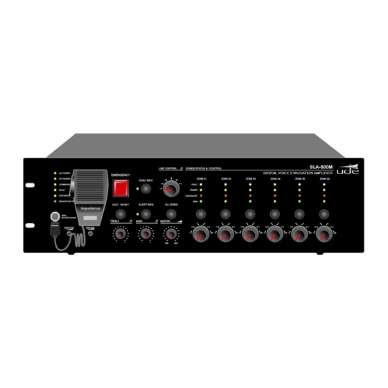
Page 5: Front Panel
UDEVAC-500 Front panel 1. AC Power indicator. Green AC power supply is currently operating normally. Yellow AC power supply has a problem. 2. DC 24V indicator. Green Backup power supply is working normally. Yellow Failure of the backup power supply. - Page 6 UDEVAC-500 Two ways to enter emergency mode and broadcast an emergency message: 1) Activate the emergency mode by pressing the red button with cap. Immediately the red light will start flashing. Then select all or those areas where you want to launch the emergency message, and press the "EVAC MSG"...
- Page 7 UDEVAC-500 12. Speaker zone failure indicator. Yellow Change in speaker impedance in circuit A or B, or the zone may be open or short-circuited. Off Current impedance of the speaker zone loop is within the impedance measured when it was first installed.
-
Page 8: Rear Panel
UDEVAC-500 Rear panel 1. 24V DC emergency power input. The DC24V power supply to be connected can be sealed lead acid batteries or similar products. Note: • Use an EN54-4 certified power supply. • Please confirm that the DC24V power supply can provide the minimum operating current for the correct operation of the SLA-500M. - Page 9 Use a pin-to-pin CAT6 UTP cable (TIE / EIA-568B standard) to interconnect all the devices that make up the UDEVAC-500 system, the maximum communication distance is up to 600 meters. Loop or star connection of all connected equipment is possible, the SF-500 software will automatically detect the connection mode of the system.
- Page 10 UDEVAC-500 9. Ground connection. 10. Backup amplifier input. 11. System fault output relay. When the system has any fault, this relay output will close (normally open contact). 12. Relé de salida del modo de emergencia. When the system operates in fire or evacuation mode, this relay will close (normally open contact).
-
Page 11: Technical Characteristics
UDEVAC-500 Technical characteristics Model SLA-500M SLA-500S Description Control equipment Expansion unit AC electrical part Power supply AC220V-250V, 50/60Hz Control equipment Power consumption 650W Maximum current <3A Fuse 250V/5A, low speed type DC electrical part Power supply 24V DC, 20V-27.5V Maximum current <27A... -
Page 12: Main Functions
UDEVAC-500 PZ-500F fireman microphone Description The PZ-500F is an E54-16 compliant, wall-mounted, fireman warning microphone. Main functions Fireman's microphone according to EN 54-16. "EVAC MSG" or "ALERT MSG" activation buttons for all zones simultaneously, "FAULT ACK" button, plus 4 programmable emergency buttons. - Page 13 UDEVAC-500 Front panel 1. Equipment power indicator. Green system has an AC or DC power failure. Yellow system works well AC and DC supplies are normal. 2. Equipment and system status indicators (FAULT) Yellow failure of some module or system equipment, please press "FAULT ACK" to cancel the warning buzzer.
- Page 14 UDEVAC-500 6. FAULT ACK button A) All the modules of the system are supervised and the diagnosis is normal, if we press this button when the FAULT light is not flashing, the equipment will not do any action or process.
- Page 15 UDEVAC-500 Technical characteristics Phantom power Voltage 20V ~ 27.5V Maximum current Less than 0.2A (with 24V power, all LEDs on and in voice prompt mode) Consumption Less than 3W MIC Performance 30mV Mechanical specifications 298 x 298 x 89 mm Net weight 3.8KGS...
-
Page 16: Main Characteristics
UDEVAC-500 Microphone desk PZ-500 and expansion keyboard PZ-500E Description The PZ-500 Microphone Desk and PZ-500E Expansion Keypad allow users to select paging zones remotely. It has a 12-zone capacity that can be expanded with the expansion keyboard and allows you to connect up to 32 looping microphones. -
Page 17: Panel Frontal Y Posterior
UDEVAC-500 Panel frontal y posterior 9 10 1. Device status indicator "busy" Green equipment is busy, please wait. Off free and can be used to call a specified zone. 2. Microphone The gooseneck microphone has a luminous ring, lit red indicates that it is ready to give a voice warning. - Page 18 UDEVAC-500 8. Connection inputs with other system devices 9. Microphone output sensitivity regulation 10. Line input for external audio 11. Device ID configuration DIP switch From the 1st to the 5th switch are to configure the address / identification of the microphone through binary system.
- Page 19 UDEVAC-500 Technical characteristics Model PZ-500 Description Microphone notification desk System capacity 32 units Communication distance 600 meters Connection system Star or redundant loop connection Number of zones 12 zones o 12 groups Announcements mode PTT or normal mode Electrical parts Supply Voltage 20V -27.5V...
- Page 20 UDEVAC-500 Operation guide Background music broadcast Connect the audio sources or microphones to the INPUT1-6 inputs on the rear panel, select the line input via the input source selector on the front panel of the main equipment or expansion equipment, connect the zone output with the corresponding background music indicator means that music is playing in that area.
- Page 21 UDEVAC-500 SF-500 Configuration software Description Equipment configuration: System Requirements: AMD / Inter CPU 2.0G, Windows XP SP3 / Window 7/8 / 8.1 / 10. Installation. Double click on “SF-500.exe” The installation will be done in a transparent way for the user, and will finish with the creation of a shortcut to the SF-500 application on the desktop of the computer.
- Page 22 UDEVAC-500 If, on the other hand, we want to assign a new IP to the SLA-500M, we can move the 5th switch of the configuration DIP switch up so that the SLA- 500M obtains an IP address from our DHCP server.
- Page 23 UDEVAC-500 System modules are operating normally Some module of the system is defective or faulty The current equipment is operating normally The current equipment is working with an error or is faulty Update Upload Save Host 01 - SLA-500M Host Host 02 - SLA-500S 610.592A...
- Page 24 UDEVAC-500 Configuration Software Operation Log In Double-click the SF-500 shortcut on the desktop to start the setup program. Once the main window of the software opens. Click a window will open to enter username and password for identity verification, the default username is "admin" and the password is empty, users can modify this password after setting the team.
- Page 25 UDEVAC-500 Menu bar and tools The system has a menu bar and tools: Enter with password and username, the default username is "admin" and the password is empty Exit the program. Import a schedule. Save a schedule. Download firmware. Configuration of network parameters.
- Page 26 UDEVAC-500 Ventana “System Control Config” "CONTROL" with this button we open the equipment control window, we can see the output status of the system zones, the "Reset", "Evac", "Alert" buttons and the input line buttons. "STATE" is used to check the connection status of all equipment connected to the SLA-500M control unit.
- Page 27 UDEVAC-500 Window “Control” In this window we can see the output status of the system zones, the "Reset", "Evac", "Alert" buttons and the input line buttons In this window we can see the groups that should have been previously configured in "Group" once all the groups have been configured, click on the corresponding group name and in window "2"...
- Page 28 UDEVAC-500 Window “State” STATE Helps us to check the connection status of all the equipment (microphone desks, expansion equipment, fire brigade microphones, etc.) connected to the SLA-500M control equipment, including the equipment itself. STATE & EQUIPMENT ID In this window the "State" will indicate the status of the equipment. A green tick means that it is connected and working correctly, if there is a red X it indicates a failure in the connection or in the equipment itself.
- Page 29 UDEVAC-500 Ventana “System Configuration” GLOBAL In this window we can select the number of connected devices, a SLA-500M control device and up to 19 SLA-500S expansion kits. The system supports a maximum of 20 computers. " In this window we can select the number of handheld microphones connected to the control equipment SLA-500M.
- Page 30 UDEVAC-500 In this window we can select one of the microphones, configured in window "9", in order to later configure that same microphone. In this window we can select and program the button of the microphone desk to assign the...
- Page 31 UDEVAC-500 "Fire mode" to configure the parameters of the actions and events that the control equipment must take in the event of an evacuation or alert message being activated. "Alarm mode config" Selecting this button will open the window (Down indicated) where we can configure: In this window we can select "All zone", "Specify...
- Page 32 UDEVAC-500 We can select one or more of the output relays that will be activated with the input contact that we are programming at this moment. We can see the information of the equipment and the contact entries, in addition, if specific zones have been selected, it will also appear which zones will be activated and from which equipment (Host 01, Host 02, etc.).
- Page 33 UDEVAC-500 "Audio priority & Line audio mode" to configure the parameters of the priorities of the different audio signal inputs, such as microphone desks, evacuation messages, music inputs, etc. ① Host index is for selecting the control equipment (Host 01) or expansion equipment (Host 02, Host 03, etc.).
- Page 34 UDEVAC-500 Click on the SF-500 Control menu: On the left it shows that there are six groups in SF-500. The right shows that there are six groups of zones in the system. The red LED on the right side indicates that the system is working in emergency mode.
- Page 35 UDEVAC-500 Window “Log” "ID" The registration number of the alarm. "CALENDAR" indicates the date and time of the registration. "LOG TYPE" It indicates the type of event (Alarm, fire warning, impedance change in a speaker zone, etc.), it can be used for searching when there are many records.
- Page 36 UDEVAC-500 Window “Other” Change password Click "User and password": and it will ask us for username and password to access. If it is incorrect, the system will automatically eject If the password entered is correct, it will show us the following window: USER NAME It means the name of the current login user.
Need help?
Do you have a question about the UDEVAC-500 and is the answer not in the manual?
Questions and answers