Table of Contents
Advertisement
Quick Links
Advertisement
Table of Contents

Related Manuals for Tekon 560


Summary of Contents for Tekon 560
- Page 1 Power Analyzer USER MANUAL Ⓒ 2018 TEKON, Inc 2018,01 버젼 1...
-
Page 2: Table Of Contents
1. General 1.1. International Standard Safety Symbol 1.2. Measurement Range (Over voltage range) definition 1.3. Safety precautions 1.4. Unpacking 1.5. Order information 2. Overview and specifications 2.1. Product overview 2.2. Nomenclature and functions 2.3. Specifications of the product 3. Using power analyzer 3.1. -
Page 3: General
1. General 1.1. International Standard Safety Symbol 기호 설명 Double insulated protection Warning. User should read marking area in the manual and need pay attention. If user does not follow the Warning –safety information, user may have physical injury and the Unit, system may be damaged Disposal information... -
Page 4: Measurement Range (Over Voltage Range) Definition
1.2. Measurement Range (Over voltage range) definition Higher Category indicates Higher Over Voltage Electric environment. Tester designed for CAT III environment can withstand higher voltage than the tester designed for CAT II To avoid any serious accident while measurement, better to use Tester higher category for the testing environment. -
Page 5: Safety Precautions
1.3. Safety precautions This instrument is designed and manufactured to be compliant with IEC 61010-1, an international standard on safety requirements for electrical equipment for measurement, control and laboratory use, and has been thoroughly tested prior to shipment to ensure it performs at its best. This user’s manual contains general safety precautions to prevent danger to the user as well as information on how best to use the instrument for a longer service life. - Page 6 l Do not exceed the maximum allowable input of any measuring range. l Never disassemble the instrument during taking measurements. - Battery l Use the battery specifically dedicated to the instrument. Do not use a battery other than that. l Charge the battery using an adapter specifically dedicated to the instrument. - Measurement leads for measuring voltage l Use the measurement lead provided with the product as standard.
- Page 7 Warning l Pay attention possibility that voltage source line under measurement is at high temperature. l Never apply the current or voltage exceeding each measurement range for a long period of time. l Do not apply voltage and current to the measurement lead for voltage or clamp sensor in the state where the power is turned Off.
-
Page 8: Unpacking
1.4. Unpacking When you receive the product, inspect the package content right away to make sure it matches the description in the seller’s listing. If the package is missing a part or there is a damaged component, immediately notify to the supplier without use. -
Page 9: Order Information
1.5. Order information 1.5.1. Accessories and replaceable parts n Voltage Test Lead(Assembly) n Clamp sensor(1000A) TC1001 TCT 1000 n AC Adapter n Bluetooth Dongle T1225 (DC12V 2.5A) T400 (BTU400) n Carry Bag n Rogowski Coil T3001C T100F... -
Page 10: Overview And Specifications
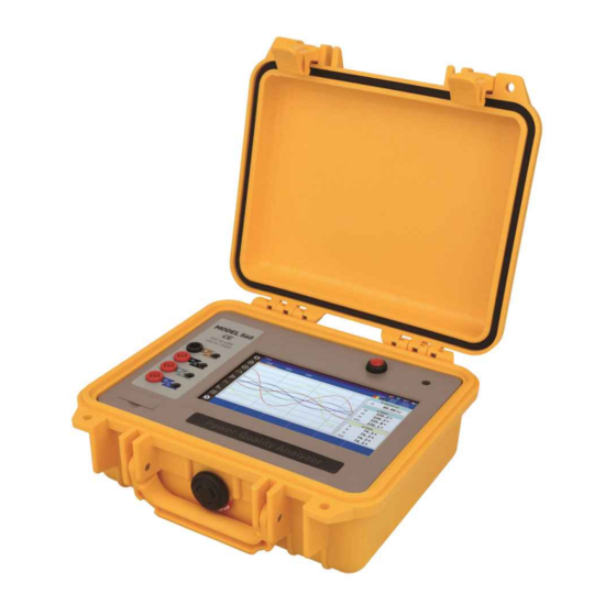
2. Overview and specifications 2.1. Product overview Ÿ TEKON 560 is a lightweight but robust handheld power analyzer designed for routine and diagnostic testing on-site of power. It incorporates 7-inch wide view touchscreen and uses rechargeable batteries. Ÿ Allows you to monitor a variety of power parameters such as power, voltage,... -
Page 11: Nomenclature And Functions
2.2. Nomenclature and functions 2.2.1. Appearance Function Description ① Power Button Power On/Off Button Socket used plugged into power outlet ② Adaptor socket charging Terminal for A power input terminal used to house the measurement ③ line input cable SD socket A slot into which SD card is inserted to save data ④... -
Page 12: Specifications Of The Product
Storage temperature -20 ~ 50°C / -4 ~ 122°F (<30 days) Charging temperature (from 40 ° C to 10 °) 104 ° F ~ 50 ° Operating: 0~2,000m (6,560 feet) Altitude Non-operating: 0 ~ 10,000 m (32,800 feet) Relative humidity 10~85% 2.3.4. - Page 13 2.3.6. Electrical specifications ■ Power Analyzer Max. input voltage(Phase–Neutral): 1000Vrms Max. input voltage(Phase–Phase): 1730Vrms Phase-Neutral input impedance: 6 MΩ Phase–Phase input impedance: 6 MΩ 16 bit 8 channels, AD converter simultaneous sampling Sampling frequency 10.24k Samples/sec Reference temperature 23°C±2°C Temperature influence 25ppm/°C Volt/Freq Range...
- Page 14 Amps Range Resolution Accuracy 300A~5000 A (AC) ± 1.5% ± 5 100F 30A~500 A (AC) 0.1 A ± 1.5% ± 5 200F Arms 3A~50 A (AC) 0.1 A ± 1.5% ± 5 (AC+DC) ± 5% 100F 0.1 A ± 5% 200F 0.1 A ±...
- Page 15 Harmonics Range Resolution Accuracy Harmonics DC, 1~50 Harmonic groups order (n) Inter-Harmonics Off, 1~50 Harmonic & Inter-Harmonic subgroups order V %f 0.0 ~ 100.0% 0.1% ± 0.25% ± n x 0.1% V %r 0.0 ~ 100.0% 0.1% ± 0.25% ± n x 0.4% V Absolute 0.0 ~ 1000 V 0.1 V...
- Page 16 2.3.7. Specifications of current probe ETCR-100F (Φ100mm) ETCR-200F (Φ200mm) User’s Manual...
-
Page 17: Using Power Analyzer
3. Using power analyzer 3.1. Getting started Press and hold the button Power to turn the power On. Then, the following screen will appear enabling you to set up functions for power metering and transformer turns ratio (TTR). Select the button to activate functions for power analysis. -
Page 18: Screen
3.2. Screen A screen that appears differs with individual measuring functions. Hereunder is the description of screens configured for the most common functions. Name Description Buttons used to convert to different functions Used to return to the previous screen Comm Locks the touchscreen;... -
Page 19: Wiring
3.3. Wiring 3.3.1. Type of wiring The power analyzer supports a variety of wiring such as 1P3W, 2P4W, OpenDelta, 3P3W, and 3P4W. 1P3W 2P4W OpenDelta 3P3W 3P4W Wiring configuration Voltage Input Current Input 1P3W UN, U1 IN, I1 2P4W UN, U1, U2 IN, I1, I2 OpenDelta UN, U1, U2, U3... -
Page 20: Metering Functions Of Power Analyzer
3.4. Metering functions of Power Analyzer 3.4.1. Screen involving power meter This is a screen enabled to check instantaneous power measurement values. Tap the icon on the left to pop you into this screen. Then, various power parameters are measured and displayed. Name Description Select to go into the screen you wish among four modes;... - Page 21 3.4.2. Metering – All Display item Active Reactive Apparent Power factor power power power Voltage Voltage Voltage (U1) RMS voltage Unbalance frequency Current Current RMS current K-Factor Unbalance 3.4.3. Metering – Voltage Display item Voltage Voltage Voltage (U1) RMS voltage Unbalance frequency Voltage...
- Page 22 3.4.4. Metering – Current Display item Current Current RMS Current K-Factor Unbalance Current Current Current Current DC value peak + peak - peak factor 3.4.5. Metering – Power Display item Active power Reactive power Apparent power Displacement Power factor power factor User’s Manual...
-
Page 23: Phase Diagram Of Power Analyzer
3.5. Phase diagram of Power Analyzer 3.5.1. Phase diagram This is a screen enabled to check phase of the power. Tap the icon on the left to move to this screen. Name Description ① Meter Display voltage/current RMS, phase, unbalance value. ②... -
Page 24: Waveforms Functions Of Power Analyzer
3.6. Waveforms functions of Power Analyzer 3.6.1. Waveforms functions of Power Analyzer This is a screen enabled to check waveforms of voltage and current in real time. Tap the corresponding icon on the left to enter into this screen. Name Description ①... - Page 25 Press the tab Voltage to make waveforms of voltage to be displayed. Press the tab Current to make waveforms of current to be displayed. User’s Manual...
-
Page 26: Harmonics Functions Of Power Analyzer
3.7. Harmonics functions of Power Analyzer 3.7.1. Function of Power Analyzer that displays harmonic data in graphs This is a screen enabled to check harmonic data of voltage and current as bar graphs. Tap the corresponding icon on the left to enter into this screen. Select Graphs on the upper tab. - Page 27 3.7.2. Function of Power Analyzer that displays a list of harmonic measurements This is a screen enabled to check harmonic measurements of voltage and current in a form of graphs. Tap the corresponding icon on the left to enter into this screen. Select List on the upper tab.
-
Page 28: Settings For Power Analyzer
3.8. Settings for Power Analyzer 3.8.1. Settings for Power Analyzer – Basic This is a screen enabling you to set configuration of the power analyzer. Tap the corresponding icon on the left to enter into this screen. Select Basic on the upper tab. Name Description ①... - Page 29 3.8.2. Settings for Power Analyzer – Other Tap the corresponding icon on the left to enter into this screen. Select Etc on the upper tab. Name Description Select the preset value for color that discriminates phases. Once selected, press OK to confirm. <UK (former model), USA, Canada, Europe (IEEE), China>...
- Page 30 [Legal rights of customer] The benefits under this warranty are in addition to other rights and remedies that you may have at law. TEKON does not exclude, limit or suspend such other rights as ensured and conferred under statute. User’s Manual...
- Page 31 MEMO User’s Manual...
- Page 32 MEMO User’s Manual...
- Page 33 203-702 Bucheon Technopark, 388, Songnae-daero, Wonmi-gu, Bucheon-si, Gyeonggi-do, Korea, 14502 TEL : 82-32-325-6030 / FAX : 82-32-325-6032 / http://www.tekon.co.kr...
Need help?
Do you have a question about the 560 and is the answer not in the manual?
Questions and answers