Table of Contents
Advertisement
Quick Links
Uninterruptible Power Supply UPS
COVER
6-10 kVA
User manual
The content of this document is the copyright of the publisher
and may not be reproduced without prior permission.
The right to modify the design and specifications is reserved without
prior notice.
Copyright 2021
COMEX S.A.
All rights reserved.
CORE
COMEX S.A.
CSA-2120.01
Advertisement
Table of Contents

Related Manuals for COMEX COVER CORE 6K


Summary of Contents for COMEX COVER CORE 6K
- Page 1 The content of this document is the copyright of the publisher and may not be reproduced without prior permission. The right to modify the design and specifications is reserved without prior notice. Copyright 2021 COMEX S.A. All rights reserved. CSA-2120.01 COMEX S.A.
-
Page 2: Table Of Contents
Transferring the UPS from Maintenance Bypass mode to normal operation ....20 5.6. Battery test .......................... 20 5.7. Mute the audible alarm ....................... 20 5.8. Installing the software ......................20 5.9. Working conditions ......................21 5.10. The storage conditions ......................21 5.11. Battery change ........................21 COMEX S.A. -
Page 3: Safety Rules
Safety rules This manual provides information on the safe use of the UPS. Before unpacking and installing the UPS, read its contents and follow its instructions. 警告 危 险 FULFILLED STANDARDS - EXECUTION EN 62040-3 Uninterruptible Power Systems (UPS): Methods for determining the characteristics and test requirements. - Page 4 • Keep these operating instructions! The manual contains important instructions on the use of the UPS that should be followed during installation and use of the UPS device and batteries. • Condensation may occur if the power supply is cold and is brought into a warm place. Therefore, you should wait at least 2 hours until it starts up.
-
Page 5: Transport, Unpacking The Ups
Transport, unpacking the UPS Check carefully whether the carton and the contents are not damaged. If any damage is found, immediately inform the shipping company and the power supply distributor. Do not throw away the UPS packaging. 1. If no damage is found, carefully open the carton. 2. -
Page 6: Vertical Mounting (Tower)
2.2. Vertical mounting (tower) To install the power supply in the Tower position, you need to use special stands that secure the power supply and enable its stable placement in a vertical position. The set of stands includes short and long connecting elements, depending on the width of the UPS set. -
Page 7: Appearance And Connection
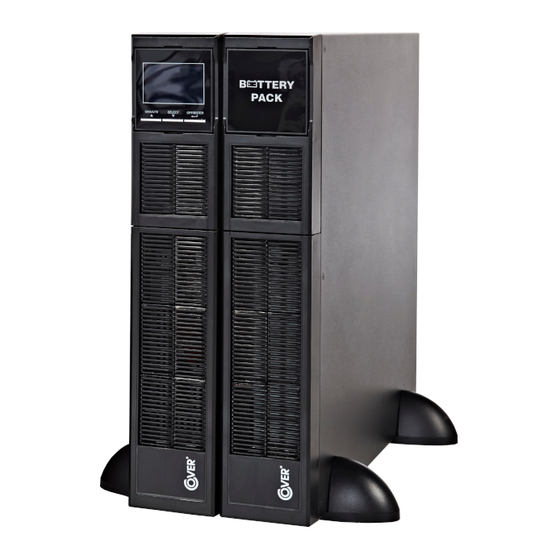
Appearance and connection 3.1. Rear panel of the UPS and battery module Fig. 1 COVER CORE 6-10K power supply Fig. 2 EBM 6/10 - 3U battery module. 1. Current connectors (only for the parallel operation version) - option. 2. Parallel operation connectors (only for the parallel operation version) - option. 3. -
Page 8: Connecting External Batteries
3.2. Connecting external batteries Make sure there is a battery circuit breaker between the UPS and the battery module. Before connecting the battery module and the UPS, the circuit breaker must be turned OFF. Make sure the number of batteries in the battery module is appropriate for the amount for which the UPS has been configured. -
Page 9: Connecting The Power Supply And Receivers
3.3. Connecting the power supply and receivers The CORE 6K and 10K UPS is designed for permanent connection through the terminal block located on the back of the UPS, as shown in the figure below. OUTPUT INPUT UPS adapted for installation in a single-phase, three-wire installation, TN with a grounded neutral. -
Page 10: Connection Of Communication Options
3.6. Connection of communication options The UPS has three communication ports: RS-232 Slot SNMP/AS-400 To enable automatic management and monitoring of the UPS, connect the USB cable supplied with the device, on one side to the USB socket on the UPS and on the other side to the USB socket on the computer. -
Page 11: Lcd Display Operation
LCD display operation 4.1. Function keys There are 4 buttons on the control panel of the UPS which are used to operate the UPS and the LCD. Button Function • Turn on the UPS: Press and hold for more than 0.5 seconds to turn on the ON/ENTER UPS. -
Page 12: Led Indicators
4.2. LED indicators The UPS is equipped with an intuitive LCD panel and four LED indicators for easy reading of the UPS status UPS. The status of the LEDs determines the current operating status of the power supply and is described in the table below: Bypass Line... -
Page 13: Lcd Display
4.3. LCD display Function Information about the time of autonomy Displays the estimated autonomy of the UPS H: hours, M: minutes, S: seconds Configuration and error information Indicates that an error or warning occurs. Displays an error or warning code. Output information Displays the voltage or frequency parameters and the battery voltage. -
Page 14: Alarm Signals
Battery information Indicates a charge level of 0-24%, 25-49%, 50-74%, and 75-100%. Indicates a defective battery condition. Indicates a low battery voltage condition. Information about power supply parameters and battery voltage Displays input voltage and frequency parameters and battery voltage. Vac: 230V mains voltage, Vdc: battery voltage, Hz: mains frequency 4.4. -
Page 15: Ups Settings Menu
4.6. UPS settings menu To enter the configuration menu, press the Test / Up + MUTE / Down buttons simultaneously for more than 1 second. View of the configuration menu and description of the possible settings below. To access all settings, the UPS should be in Stand-by mode (no voltage at the UPS output) or Bypass mode (parameters 15 and 16 are available while the inverter is running). - Page 16 04 – Frequency tolerance range for Bypass Parameter 2: Lower Voltage Tolerance Range for Bypass. 50Hz: possible settings 46-49Hz (default 46Hz) 60Hz: possible settings 56-59Hz (default 56Hz) Parameter 3: High voltage tolerances for Bypass. 50Hz: possible settings 51-54Hz (default 54Hz) 60Hz: possible settings 61-64Hz (default 64Hz) 05 –...
-
Page 17: Description Of The Ups Operation Modes
13 – Battery voltage regulation Parameter 2: Choose “Add” or “Sub” to make battery voltage Up / Down adjustment. Parameter 3: Voltage regulation range 0 - 5.7V (default 0V). 14 – Charger voltage adjustment Parameter 2: Choose “Add” or “Sub” to make the Charger Voltage Up / Down adjustment. - Page 18 Economy mode ECO mode If the supply voltage is within tolerance, the supply voltage is supplied directly to the UPS output. The inverter is in Stand-by mode, which increases efficiency and reduces operating costs. CVCF converter If the frequency of the supply voltage is within the range of 46 ÷ 64Hz, it is possible to set a fixed value of the frequency of the output voltage 50 or 60Hz.
-
Page 19: Ups Warnings And Audible Alarms
4.8. UPS warnings and audible alarms Warning Icon (blinks) Alarm Low battery voltage Beeps every second Overload Beep 2x / second Battery non connected Beeps every second Overload Beeps every second Power fuse damaged Beeps every second EPO input active Beeps every second Fan error / Overheating Beeps every second... -
Page 20: Fault Codes - Active In Fault Mode (Fault Led Active)
4.10. Fault Codes - Active in Fault Mode (Fault LED active) Code Icon Fail BUS start error High BUS voltage BUS low voltage BUS voltage unbalance Inverter start error Inverter voltage is too high Inverter voltage is too low Short circuit on the inverter output Reverse power at the inverter output Battery thyristor short circuit Inverter relay shorted... -
Page 21: Ups Operation
UPS operation 5.1. Turn on the UPS from the mains 1. Turn the battery disconnect switch located on the rear panel of the battery module or near the battery cabinet for external batteries to the ON position. 2. Switch on the UPS power in the UPS switchboard. When power is applied, the LCD panel lights up and the fans start to run. -
Page 22: Transferring The Ups To The Maintenance Bypass Mode
5.4. Transferring the UPS to the Maintenance Bypass mode The following procedure is for a UPS equipped with an external Maintenance Bypass. Switching the UPS to the Maintenance Bypass mode means that the receivers are not protected against power failures. 1. -
Page 23: Working Conditions
5.9. Working conditions To ensure proper working conditions for the uninterruptible power supply system, the room with the power supply must be dry, clean and free of dust and dirt. From time to time (at least every 6 months or more often depending on the degree of soiling), clean the ventilation openings on the power supply to ensure free air flow.
Need help?
Do you have a question about the COVER CORE 6K and is the answer not in the manual?
Questions and answers