Table of Contents
Advertisement
Quick Links
USER GUIDE
SCC-A10 Voltage Attenuator
Module
Conventions
<>
»
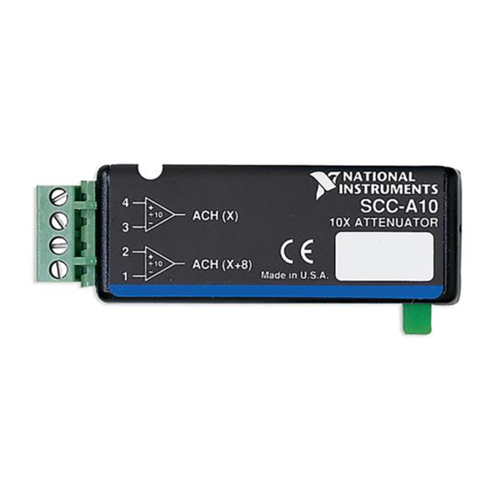
The SCC-A10 voltage attenuator module accepts up to two voltage sources
of 100 V maximum amplitude and attenuates each voltage by a factor of 10.
A differential instrumentation amplifier buffers each input signal. The
SCC-A10 contains circuitry capable of protecting E Series DAQ devices
for input signals up to 250 V
The following conventions are used in this guide:
Angle brackets that contain numbers separated by an ellipsis represent
a range of values associated with a bit or signal name—for example,
P0.<3..0>.
The » symbol leads you through nested menu items and dialog box options
to a final action. The sequence File»Page Setup»Options directs you to
pull down the File menu, select the Page Setup item, and select Options
from the last dialog box.
This icon denotes a note, which alerts you to important information.
This icon denotes a caution, which advises you of precautions to take to
avoid injury, data loss, or a system crash. When this symbol is marked on
the product, refer to the Read Me First: Safety and Radio-Frequency
Interference document, shipped with the product, for precautions to take.
When symbol is marked on a product, it denotes a warning advising you to
take precautions to avoid electrical shock.
When symbol is marked on a product, it denotes a component that may be
hot. Touching this component may result in bodily injury.
.
rms
Advertisement
Table of Contents

Related Manuals for National Instruments SCC-A10


Summary of Contents for National Instruments SCC-A10
- Page 1 USER GUIDE SCC-A10 Voltage Attenuator Module The SCC-A10 voltage attenuator module accepts up to two voltage sources of 100 V maximum amplitude and attenuates each voltage by a factor of 10. A differential instrumentation amplifier buffers each input signal. The...
-
Page 2: What You Need To Get Started
SC-2345 refers to both the SC-2345 connector block and the SC-2345 configurable connector. SCC refers to any SCC Series signal conditioning module. What You Need to Get Started To set up and use the SCC-A10, you need the following items: ❑ SC-2345/2350 with one of the following: –... -
Page 3: Device Specific Information
Refer to the Read Me First: Safety and Radio-Frequency Interference document before removing equipment covers or connecting/disconnecting any signal wires. You can plug the SCC-A10 into any analog input socket on the SC-2345. The socket you choose determines which E Series DAQ device channels receive the SCC-A10 signals, as explained in the SCC Quick Start Guide. -
Page 4: Connecting The Input Signals
SC-2345 socket where you plug in the module, J(X+1) or J(X+9). The signal source can be floating or ground-referenced. Floating signal sources do not require bias resistors to ground with the SCC-A10. Figure 1 shows the SCC-A10 signal connections. SCC-A10... -
Page 5: Specifications
E Series DAQ device by 10 to get the correct SCC-A10 input voltage. Specifications In order for the SCC-A10 to perform according to the specifications in this guide, Note the ±15 V power supply you use must be accurate to within 5%. -
Page 6: Dynamic Response
Channel-to-channel.........100 V, Installation Category I Environmental Operating temperature ......0 to 50 °C Storage temperature ........–20 to 70 °C Humidity ..........10 to 90% RH, noncondensing Maximum altitude........2,000 m Pollution Degree (indoor use only) ..2 SCC-A10 Voltage Attenuator Module User Guide ni.com... -
Page 7: Electromagnetic Compatibility
Safety The SCC-A10 meets the requirements of the following standards for safety and electrical equipment for measurement, control, and laboratory use: • IEC 61010-1, EN 61010-1 • UL 3111-1:UL 61010B-1 • CAN/CSA C22.2 No. 1010.1 For UL and other safety certifications, refer to the product label, or visit... - Page 8 AI (X) and AI (X+8). A GND is the reference for the ±15 V power supply. AI GND and A GND connect to the SC-2345 at the SCC-PWR connector. Table 1. SCC-A10 Module Pin Assignments Pin Number Signal...
- Page 9 *371067B-01* Corporation. Product and company names mentioned herein are trademarks or trade names of their respective companies. For patents covering National Instruments products, refer to the appropriate location: Help»Patents in your software, the patents.txt file on your CD, or ni.com/patents.
Need help?
Do you have a question about the SCC-A10 and is the answer not in the manual?
Questions and answers