Table of Contents
Advertisement
Advertisement
Table of Contents

Related Manuals for Sankosha LP-570E-V2


Summary of Contents for Sankosha LP-570E-V2
-
Page 1: Instruction Manual
LP-570E-V2 Instruction Manual Instruction Manual For your safety, please read this Instruction Manual carefully and understand all instructions before starting operating of the machine. If at any time you have any questions, please do not hesitate to contact us. - Page 2 Welcome Thank you for choosing our LP-570E-V2. Single Buck Shirt Press This machine was delivered to you after thorough inspection at our plant. Please read this manual carefully for proper usage of this machine. Product Specifications Model LP-570E-V2 Capacity Up to 60 shirts / hour Power 3 phase 400V 50Hz 1.6kW...
-
Page 3: Table Of Contents
Table of Contents INSTRUCTION MANUAL ......................1 Safety Guidelines ..................... 4 Hazardous Area ....................7 Electrically Live Area ....................... 7 Machine Moving Area ...................... 8 High Temperature Area ....................9 Safety Labels on the Machine ................. 10 Main Devices ....................11 Control Unit .................... -
Page 4: Safety Guidelines
Sankosha cannot be held legally responsible for any injuries to operators or damages to the machine caused by alterations to the machine or operations not described in the machine manual. - Page 5 Do not put a finger or metal into the machine should be performed only by an authorized or Control Box. Sankosha distributor or by qualified It may cause electric shock or explosion. personnel who has read this manual. Improper installation or rigging of this machine may result in shock, injury or burn.
- Page 6 It may cause electric shock without power-off. ■ Check and cleaning Electric plugs and electric sockets need to be checked and cleaned periodically. If you find any damage, call us or your Sankosha distributor. Breakage can cause electric shock and fire. ■ Adequate space Adequate space around the machine should be secured for service and maintenance.
-
Page 7: Hazardous Area
Hazardous Area Electrically Live Area DANGER Control box has terminals with lethal voltage. -Only maintenance personnel can open the box. -Turn off the power before opening the box. Ignoring this warning will result in serious injury or death due to electrical shock. -
Page 8: Machine Moving Area
Machine Moving Area WARNING The machine has some moving areas along many portions. Keep your hands away from the moving area during operation. Before starting check up or maintenance, turn off the air and power first. Ignoring this warning could result in serious injuries. Around the Tuck Press and Shoulder Press Base Around the Tuck Press Base Around the Front Press... -
Page 9: High Temperature Area
High Temperature Area CAUTION The machine has Press Heads which get extremely hot during operation. Never touch Pressing surface during and for 30 minutes after the steam has been turned off. Ignoring this warning may result in burns. Shoulder Press Tuck Press Rear Press Tuck Press... -
Page 10: Safety Labels On The Machine
Safety Labels on the Machine ⑦ ⑦ ② ⑪ ④ ⑦ ⑪ ⑦ ⑩ ⑩ ⑩ ⑥ ⑫ ① ③ ⑬ ⑦ ⑨ ⑧ ⑥ ⑤ ⑮ (Inside Control Box) ⑭ ① ② ③ ④ It may cause electric shock. ⑤... -
Page 11: Main Devices
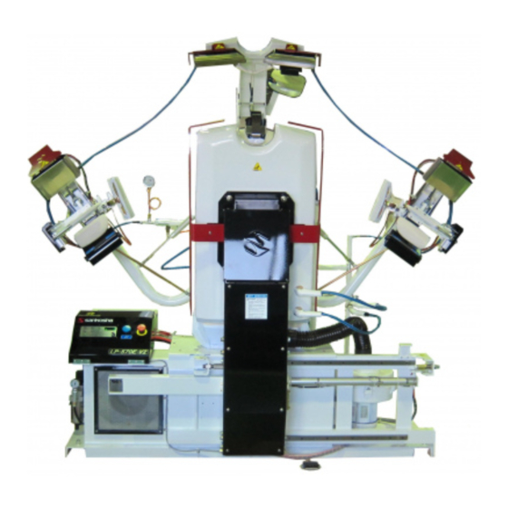
Main Devices Shoulder Press Front Neck Clamp Front Press Rear Press Short Sleeve Set Front Press Safety Guard Cuff Set Body Tail Clamp Transfer Solenoid Valve Box Control Box Operation Panel Regulator (Air Intake) Foot Pedal Filter Tuck Press Safety Guard Tuck Press Back Shoulder Press Safety Guard... -
Page 12: Control Unit
Control Unit Control Box ③ ② ⑥ ⑤ ④ ⑬ ⑭ ⑨ ⑧ ⑦ ⑫ ⑪ ⑩ ⑮ ① ① Power Switch The switch is for the main power. Black button is for turning the Power ON. Red Button is for turning the Power OFF. ②... - Page 13 ⑦ Size Adjustment Button (green lamp will flash when it is ON) This button will make the sleeve arm position closer to the body when it is ON. It is very useful if the short sleeve is too small to reach the original position. ⑧...
-
Page 14: Operation Box
Operation Box Operation Box Left Operation Box Right ④ ① ② ③ ⑤ ① Cuff Clamp Button Press this button to clamp left cuff or short sleeve cuff. It must be complete up to tail clamp operation. If you release the button before taking the next step, the clamp will open. -
Page 15: Operation Procedures
Operation Procedures Follow the procedure for proper operation. Caution Improper operation can cause mechanical failure or injury to operators. Provide Air Check whether air pressure is set at the required level for main regulator and other regulators as ① below. -
Page 16: Provide Steam
Provide Steam Check whether steam with the pressure at 0.6MPa or more can be supplied to the machine. If the steam pressure does not reach required level, it may adversely affect shirt finishing quality. Always check whether the steam pressure meets its requirement. ... -
Page 17: Set Each Timer According To The Material Of The Shirt
Set each timer according to the material of the shirt How to set Long Timer / Short Timer ① Press Long Timer button or Short Timer button. (either button which is selected lamped) ・When you choose long cycle timer, you can change timer for long cycle. ・・・it shows current long cycle timer on display. -
Page 18: Set The Shirt
Set the Shirt ・Beware of pinching hands or garment by moving part during the CAUTION operation. ・Please take precautions against burning yourself at metal parts of press ・ There are tips on how to finish the garment very well at each process. ・... - Page 19 Set the Neck Set the neck and step on the Foot Pedal. → The Neck Clamp will close. ※If you want to set the neck again, press the Reset Button (blue). The Neck Clamp will open, and you can set the neck once again. ※In order to set the neck after the tail of shirt is set, step on the Foot Pedal.
- Page 20 Set the Tail After smoothing out the back of the shirt from top to bottom with both hands, step on the Foot Pedal and pull the tail at the same time. → The Tail Clamp closes, and the vacuum starts to work. ※...
- Page 21 Set the Front ・ After the Tail Clamp closes, vacuum starts to work and side expanders come out. Remove all the wrinkles by pulling the shirt down. ! ! Set the left (button) side Remove wrinkles by holding and lifting the shirt up to here as seen in this Figure.
- Page 22 Set the right (button hole) side Set the right side as same as the left side. If there is a pocket, smooth out the air by the back of the hand moving from bottom to top of the pocket. ! !...
- Page 23 1: Set the Long Sleeve Make sure that the Short Sleeve Button is OFF. ● Set the Left Cuff Insert the Cuff into the Press Pad holding it by the right hand. ● It is easy to insert when using the left hand as seen in this Figure.
- Page 24 ● While holding the cuff in place with the right hand, press the Cuff Clamp Button by the left hand. (Do not let go of the button.) Clamp → The cuff is clamped. * Be careful not to pinch your finger. ※...
- Page 25 2: Set the Short Sleeve ● Press the Short Sleeve Button on the operation panel. (The lamp turns ON.) Short Sleeve ● Move both the left and right short sleeve device Device to the front position. Set the Left Short Sleeve ●...
-
Page 26: After Operation Is Over
Informatio ・ Press the Reset Button during the automatic operation, and then all the processes will stop working. ・ Step on the Foot Pedal while Blower works, then the blower time can be extended. The Blower timer can be extended 5 seconds by every step. (Maximum: 99 seconds) All the presses open and complete when the setting time is over. -
Page 27: Other Operations
Other Operations How to Reset Emergency Stop (Safety Error) In case the Emergency Stop Button or Safety Guard at the Front Press/Shoulder Press/Tuck Press is activated, the buzzer goes off and all of the operations will stop working. All the presses (Shoulder/Body/Tuck) begin to open and the display window will show an error. -
Page 28: How To Replace The Cover & Padding
How to Replace the Cover & Padding Please turn off the power when replacing covers and padding. Please let the Caution machine cool down completely before replacing covers and padding. Ignoring this warning may result in burns. Tail Clamp 1. How to Install Tail Clamp Cover (1)... -
Page 29: Body
Body Cover and Padding can be replaced separately. 1. How to Install Body Pad (1) Install Pads to Body in following order: Body SH Silicone 10mm→ Body Spring Felt Pad 13mm. (2) Install the Pad so that the seam line of each Pad matches to the ridge of Body Shoulder. Make sure right and left are evenly set. - Page 30 2. How to Install the Body Cover Caution ・ Stainless Steel Rod is installed at front and rear side of the Body Cover. When replacing covers, remove the Steel Rods and install covers in the following order. 2-1.Install Body Cover (1)...
- Page 31 2-2. How to Install the Tail of the Body Cover (1) Zipper Tail Clamp Receiver Cover and Body Cover and attach Velcro [b] and Velcro [B]. Tail Clamp Receive Zipper (Body Cover) Velcro [b] Zipper (Tail Clamp Receiver Cover) Rear Bottom String① Velcro [B] Velcro [b] Rear Bottom String②...
-
Page 32: Neck Clamp
Neck Clamp (1) Put the Neck Clamp Orange Silicone in the Neck Clamp Cover facing the smooth side of the Silicone to the cover. (2) Install the Neck Clamp Cover (with Silicone) over the Neck Clamp Arm from the back side of the Arm. -
Page 33: Test Operation
Test Operation Before using the test operation, make sure there is no one working WARNING near the machine. The Test mode operation enables the machine to run the process by process while the machine runs all the functions continuously on the normal operation. Step 1: Press the “Test”... - Page 34 Test Number List Test Item Remarks Test No. Magnetic Contactor for Vacuum Motor Magnetic Contactor for Blower Motor Shoulder Press Solenoid (No.3) ・ Buzzer sounds after 0.4 seconds from start to move Tail Clamp Up/Down Solenoid upper, and does after 0.7 seconds from start to move (No.4) lower, please adjust speed using buzzer.
- Page 35 Test No Test Item Remarks You can check and change the DIP switch setting. Dip Switch Please see “DIP Function” on page 40. Press the Counter Clear Button to finish. You can check and change the Volume function. Service timer (Volume) Please see “Volume Function”...
-
Page 36: Service Menu
Service Menu Do not touch anywhere due to the potential danger when you open the WARNING control box. The initial setting will be changed without prior notice at the time of model changes. Caution Press the Service Button (BP1) on the main circuit board in the control box; you can check the “Input Test”, “Output Test”, “Volume Control”, “Dip Switch Set”... - Page 37 ■ Service Menu List (Please read the following list for the details which is written as Service Menu Explanation. ) Display Meaning Function For “input test 1” For “input test 2” For “output test” For volume control setting For dip switch select For timer change which is shown the number on display For reset all program to standard of factory shipping (default)
- Page 38 Chart 1 “Input Test 1” List Button / Pedal / Sensor Disp. No. Button / Pedal / Sensor Disp. No. Left Cuff Clamp Button Front Press Left Position Sensor S 10 Front Press Left Speed Reduction Shoulder Press/Slide Start Button S 11 Sensor Front Press Right Speed Reduction...
- Page 39 Chart 2 “Output Test” List ( continue from previous page ) Disp. No. Output Name Remark Neck Clamp Close Solenoid Solenoid No.18 Front Press Left Transfer Solenoid Solenoid No.9 Front Press Right Transfer Solenoid Solenoid No.10 Tuck Press Close Solenoid Solenoid No.11 Side Expander Open Solenoid Solenoid No.13...
- Page 40 5. diP (Dip Switch) ・ According to instructions 1 and 2, you will see on the display, please push the “Enter” button No.4. ・ Dial the “Setting & Select” knob No.5, the dip switch number will be shown on the display (reference Chart 4), so select the dip switch you want to change.
- Page 41 6. tou (Timer change which is shown on display) ・ According to instructions 1 and 2, you will see on the display, please push the “Enter” button No.4. ・ Dial the “Setting & Select” knob No.5, the Timer List will be shown on the display (reference Chart 5), so select the timer you want to change.
-
Page 42: Trouble Shooting
◎ During the operation, if something is wrong an error number shows up at the Display Window on the Operation Panel. Check below List, and take the necessary action. Call your dealer or Sankosha if the normal operation does not resume. It is extremely dangerous in Control Box. - Page 43 1. Error Item Error 2. Error Description 3. Check Point 1. Shoulder Press Left Safety Guard 2. Shoulder Left Press Safety Guard Switch is kept activating 3. (1) In the case of keep pushing the safety bar, it will be shown “- - 4” if you release the bar.
- Page 44 1. Error Item Error 2. Error Description 3. Check Point 1. Front Press Press Position Sensor Error 2. It is not detected Front Press Press Position sensor (SQ10) even if press head is at position. 3. (1)When you touch magnet to sensor at the rod side (left) of cylinder, the red light of sensor ①...
- Page 45 1. Error Item Error 2. Error Description 3. Check Point 1. Left Cuff Clamp Button Error 2. (1) Cuff Clamp Button keeps activated if the button is kept pressing by something when the main power is ON, or the machine is at the original position. (2) Cuff Clamp Button is kept pressing for more than 5 seconds even if you release the button.
- Page 46 1. Error Item Error 2. Error Description 3. Check Point 1.Shoulder Press Close Sensor Error 2. It is not detected Shoulder Press Close sensor (SQ06) even if press is activated. 3. (1) When you touch magnet to sensor at the rod side of cylinder, the red light of sensor … ①...
- Page 47 1. Error Item Error 2. Error Description 3. Check Point 1. Vacuum Motor Thermal Switch 2. Thermal of Magnetic Contactor KM01 for Vacuum Motor works. 3. Green trip of Magnetic Contactor is retracted and you can’t see it when it works. In case of Thermal of Magnetic Contactor works, it is considered overload by wire cutting or continuous motor running under the high temperature.
-
Page 48: Daily Maintenance
Use “Item Check List” for checking the correct service procedures. If at any time you have any questions, please do not hesitate to contact your Sankosha dealer or us. Check Item List... -
Page 49: Check Item (Daily)
Check Item (Daily) Air Pressure: Figure-1 Please make sure if the air pressure gauge at the regulator is at the standard level. See “Main Devices” and “Operation Procedure* Provide Air” in the Instruction Manual for the installation location and standard pressure level. [How to Adjust Pressure]... - Page 50 Steam Pressure Gauge (0.6MPa) Steam Pressure: Figure-3 Check the steam pressure gauges (0.6MPa). ※If the steam pressure does not reach the required level, it may adversely affect the shirt finishing quality. 4. Steam trap check: Figure-3 Check to see if the Steam Trap works properly. If not, it may malfunction.
-
Page 51: Check Item (Monthly)
8. Blower filter check: Figure-5 Check to make sure the Blower Filter is not clogged by any dirt and dust. If so, clean immediately. If you keep using the filter without cleaning, this can cause poor finishing quality as well as a decrease in the blower power. -
Page 52: Item Check List
Item Check List Check Item (Daily) Item Air Pressure Regulator /Mist Separator Steam Pressure Steam Trap Cover Press surface Emergency stop Blower filter Item Air Pressure Regulator /Mist Separator Steam Pressure Steam Trap Cover Press surface Emergency stop Blower filter Check Item ( Monthly Item... -
Page 53: Spare Parts List
Spare Parts List Index 1: Motor Operation Diagram 2: Air Piping (1) 3: Air Piping (2) 4: Air Piping (3) 5: Steam Piping Diagram 6: Control Box/Switch Diagram 7: Cover Diagram... -
Page 54: Motor Operation Diagram
Motor・Operation Diagram REV: 4 Motor Operation Diagram... - Page 55 1. Motor・Operation Diagram REV:4 Part Name Part Number Q'ty Remark LM Guide E0B006 Front Press (Upper) LM Guide Block E0B001 LM Guide E0A013 Front Press (Lower) LM Guide Block E0A001 LM Guide E0A003 Rear Press LM Guide Block E0A001 104 Joint E0F001 105 Shock Absorber F0K005...
-
Page 56: Air Piping (1)
Air Piping (1) REV: 3 Air Piping (1) 3DLP570E-V2-052-2... -
Page 57: Part Name Part Number
2. Air Piping (1) REV:4 Part Name Part Number Remark Q'ty 201 Cylinder B0K016 Front Press Slide 202 Cylinder Sensor B5A003 203 Joint C0C054 204 Floating Joint E5L001 B1H001 Front Press Cylinder 206 Cylinder Sensor B5A004 207 Speed Controller C1A024 208 Speed Controller C1A026 B2C008... -
Page 58: Air Piping (2)
3: Air Piping (2) REV: 3 Air Piping (2) 3DLP550J-V2-053-6... - Page 59 3. Air Piping (2) REV:4 Part Name Part Number Q'ty Remark B1A008 Cuff Clamp Cylinder 302 Joint C0E003 B1C007 Short Sleeve Cylinder 304 Knuckle Joint B6A003 B1A005 Tail Clamp Up/Down Cylinder B0C002 Sleeve Arm Cylinder 307 Speed Controller C1A003 308 Link Ball E5J004 309 Spring H0D002...
-
Page 60: Air Piping (3)
4: Air Piping (3) REV: 3 Air Piping (3) 3DLP550J-V2-054-6... -
Page 61: Rev:4
4. Air Piping (3) REV:4 Part Name Part Number Q'ty Remark 401 Manifold Valve A0F125 A0E013 No.5,21 : Sleeve Arm Solenoid Valve A0E013 No.9,10 : Front Press Slide Solenoid Valve 403 Joint C0C004 404 Joint A0J007 405 Joint C0G002 406 Silencer C0A003 407 Manifold Valve A0F129... -
Page 62: Steam Piping
Steam Piping REV: 3 Steam Piping 3DLP570E-V2-055-1... - Page 63 5. Steam Piping REV:4 Part Name Part Number Q'ty Remark 501 Flex. Hose A6B020 502 Flex. Hose A6B018 503 Flex. Hose A6B017 504 Steam Nozzle UNA013 505 Steam Gauge J0A003 506 Y Type Strainer J2M011 507 Ball Valve J6A007 508 Piston Valve A0G003 509 Lift Check J2J001...
-
Page 64: Control Box・Switch Diagram
6: Control Box・Switch Diagram REV: 3 Control Box・Switch Diagram 3DLP550J-V2-056-6... - Page 65 6: Control Box・Switch Diagram REV:4 Part Name Part Number Q'ty Remark 601 Breaker Switch 21C006 Push Button Switch 21I111 Reset Push Button Switch Cap 21I133 603 Push Button Switch 21I107 Emergency 604 Push Button Switch 21I085 Safety Guard 605 Push Button Switch 21I148 Start Foot Pedal Unit...
-
Page 66: Cover Diagram
7: Cover Diagram REV: 3 Cover Diagram 3DLP570E-V2-057-3... - Page 67 7. Cover Diagram REV:3 Part Name Part Number Q'ty Remark 701 Body SH Silicone 10mm S1B555 702 Body Spring Felt Pad 13mm S1B554 703 Body Cover S1B553 704 Tail Clamp Cover S1B556 705 Front Tuck Cover S1B062 706 Front Tuck Felt Pad (Left) 5mm S1B063 707 Front Tuck H Silicone 6mm S1B065...
-
Page 68: Attached Diagram
Attached Diagram Sensor Diagram Electric Connection Diagram 1/4~4/4 Steam Piping Diagram Air Connection Diagram... - Page 69 S e n s o r D i a g r a m S E 0 5 : S h o u l d e r P r e s s R i g h t ...
- Page 74 S t e a m P i p i n g D i a g r a m ( I n l e t ) ( ...
- Page 76 口 1/2”B LP-570E-V2X Rev. 6 2019. 6...
Need help?
Do you have a question about the LP-570E-V2 and is the answer not in the manual?
Questions and answers
Front buck is not opening
The front buck on the Sankosha LP-570E-V2 may not be opening due to the activation of the Emergency Stop Button or a Safety Guard. When this happens, the buzzer sounds, and all operations stop. The display window will show an error, and all presses (Shoulder/Body/Tuck) will begin to open.
To release the emergency stop:
- If the Emergency Stop Button was pressed, turn it to the right to release the lock, then press the Reset Button.
- If a Safety Guard was triggered, press the Reset Button to restart the machine.
Additionally, sensor errors or air pressure issues may also prevent the front buck from opening. Check the Front Press Close Sensor (SQ09) and Front Press Original Position Sensor (SQ13). If the sensors do not detect the correct position, adjust them or check for sensor damage, loose connections, or air pressure problems (Main Pressure: 0.6 MPa).
This answer is automatically generated
how to connect transformer back to the system