
Related Manuals for Sankosha LP-660E-V2


Summary of Contents for Sankosha LP-660E-V2
- Page 1 LP-660E-V2 Instruction Manual For your safety, please read this Instruction Manual thoroughly. If at any time you have any questions, please do not hesitate to contact us.
-
Page 3: Welcome
Welcome Thank you for choosing our LP-660E-V2. Single Collar Cuff Press This machine was delivered to you after thorough inspection at our plant. Please read this manual carefully for proper usage of this machine. Product Specifications Model LP-660E-V2 Power Single phase 100V/230V 0.8A/0.4A... -
Page 4: Table Of Contents
Table of contents WELCOME ................1 Safety Guidelines ................3 Hazardous Area ................6 Electrically Live Area ................6 Range of the Machine in Motion ............7 High Temperature Area ................8 Safety Labels on the Machies ............9 Main Device ..................10 Main Unit .................... -
Page 5: Safety Guidelines
Sankosha cannot be held legally responsible for any injuries to operators or damage to machines caused by alterations to machines or operations not described in the machine manual. - Page 6 Do not place your hands or any foreign should be performed only by an authorized objects in the area. Sankosha dealer or by qualified personnel. Incorrect installation or rigging of this machine may It may cause an electrical shock or explosion.
- Page 7 CAUTION ■ Maintenance of warning labels The labels need to be cleaned and changed if necessary. It may cause an accident. ■ Inside use only The machine must be located inside a facility. Don’t place it in a damp or wet area. It may cause an accident.
-
Page 8: Hazardous Area
Hazardous Area Electrically Live Area DANGER Control box has terminals with lethal voltage. -Only qualified person can open the cover. -Shut off the power before opening the cover. Ignoring this warning will result in serious injury or death due to electrical shock. -
Page 9: Range Of The Machine In Motion
Range of the Machine in Motion WARNING The machine has some moving areas along any portions. Keep your hands away from moving area during operation. Before starting check up or maintenance, turn off the air and power first. Ignoring this warning could result in serious injuries. -
Page 10: High Temperature Area
High Temperature Area CAUTION The machine has hot surfaces, which get extremely hot during operation. Never touch hot surfaces during and for 30 minutes after the steam has been turned off. Ignoring this warning may result in burns. -
Page 11: Safety Labels On The Machies
Safety Labels on the Machines ⑤ ⑥ ⑥ ⑤ ⑦ ⑧ ④ ③ ③ ① ③ ⑦ In the box ② ⑩ ⑥ ⑨ ⑨ Please be sure to check that nobody is on the periphery of the machine while operating ①... -
Page 12: Main Device
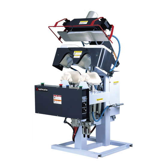
Main Device Main Unit Right Safety Bar Left Safety Bar Collar Press Head (Upper Press) Cuff Press Head (Middle Press) Cuff Table Control Panel Electric Box Steam Gauge Solenoid Valve Steam Inlet Main Switch Regulator (Air Inlet) Steam Outlet... -
Page 13: Control Box
Control Box ④ ② ③ ⑥ ⑤ ① ① Main Switch If you the push black button, the machine will turn ON and you can use the machine. ② Emergency Stop Button When you push the emergency stop button, the machine will return to it’s original position, during any process, safely. -
Page 14: Control Panel
Control panel ⑨ ① ② ③ ④ ⑤ ⑥ ⑧ ⑦ ① ・ Button (If you push this button, the green light will turn on.) Collar Cuff When this button is pushed, both the cuff (Middle press) and collar (Upper press) will press. When turning this button off (green light goes off), only the collar area (upper press head) works. - Page 15 About the display of cover counter and press counter Maximum counter is 9,999,999. The counter shows twice due to the limited space of Display Window. First it shows upper 3 digits. Turn the Set/Select Dial to the right next. It shows lower 3 digits next. When displaying the upper 3 digits, there will be a period placed in the window to denote which set of numbers the user is currently viewing.
-
Page 16: Operation Procedures
Operation Procedures Follow the procedure for proper operation. CAUTION Improper operation can cause mechanical failure or injury to operators. 1. Provide Air The standard air pressure of this machine is set at 0.6Mpa. Please make sure with the pressure gauge that the air pressure is 0.6Mpa. -
Page 17: Provide Steam
2. Provide steam The standard steam pressure of this machine is set at 0.6Mpa. Please make sure that the steam pressure is 0.6Mpa (85psi). If the steam pressure does not reach the required level, it may adversely affect the shirt finishing quality. ... -
Page 18: Set The Shirt
・Be careful to insert a hand or a shirt during work. ・Be careful not to touch the metal parts on garment setting up. CAUTION It may cause burn. 5. Set the shirt Set the cuffs on the cuff tables. See picture on right. ①... -
Page 19: After Operation Is Over
Tips * If long timer is selected during press, long timer lamp button will light. If short timer is selected during press, short timer lamp button will light. * Press the reset button to release the press position. ⑥ Collar and cuff press head will be released automatically after the timer complete. -
Page 20: Other Operations
Other Operations How to Reset Emergency Stop Pressing the emergency stop button or safety bars will make all operations stop and will return the machine to the start position. The display will display“E 1” (Emergency button) “E 2”(Left safety bar) and “E 3 ”(Right safety bar). -
Page 21: Cover/Pad Change Instruction
CAUTION Turn the power off before doing this operation. Use a cover supplied by Sankosha. Using another company’s cover may give a bad finish; Sankosha can take no responsibility if this is done. 1. How to change the Collar Cover/Pad ①... - Page 22 ⑤ Fit the collar silicon sponge and collar spring felt pad 10 ㎜, then install them to collar cover without wrinkles. Place the silicon sponge at the lower side than the spring felt pad 10 ㎜. Insert the stainless rod to the collar cover. (3 Rods) Stainless rod (short) Collar silicone sponge Collar cover 10 ㎜...
- Page 23 ⑧ Attach with the screws to fix the stainless rod with guard plate. Stainless rod Guard plate Fixed screw (3 Pcs.) ⑨ Then, tighten both of wing bolts equality. It will be pulled the color cover gradually. Wing bolts ・Clockwise: The Collar Cover is stretched ・Counter-clockwise: The Collar Cover is loosened.
-
Page 24: How To Change The Cuff Cover/Pad
2. How to change Cuff Cover/Pad When working continuously from changing the collar cover, provide air to raise up Middle Press to upper position. A cuffs cover has right and left. Tips Please attach so that a name tag and a string become outside. ①... -
Page 25: Service Menu
Service Menu It is extremely dangerous in Control Box. WARNING Do not touch anywhere unless otherwise specified. When service button (BP1) on board in control box is pushed, initialization of volume setting and check of program version and running time are possible as well as input test, output test, volume function setting, dip function setting, and timer setting. - Page 26 ■Service Menu List (Please see “Service Menu Explanation” for further details.) Display Displayed word Function Input test 1 is operated. Input test 2 is operated. Output test is operated. Each volume setting. Dip function setting. Time setting displayed in display window. Initialization of volume setting is operated.
- Page 27 2. In2 (Input test 2) ・ After 1.2 process, when is displayed, push ④Enter button. ・ When ⑤Set/Select Dial is turned, input display number registered in software (Table -1) is displayed by turns. The lamp of ③Short button will be turned on if displayed input sensor is in ON setting.
- Page 28 diP(dip function setting) ・ After 1, 2 process, when is displayed, push ④Enter button. ・ After display number (table4) is selected with ⑤Set/Select Dial, when ④Enter button is pushed, present setting is displayed. Setting is changed with ⑤Set/Select Dial and push ④ Enter button to save it.
- Page 29 7. Def(Volume setting initialization) Display by Operation Procedure 1 and 2. Press ④Enter Button to select. ・OFF" shows up at the Display Window. Turn ⑤Set/Select Dial to set it "ON". ・Press ④Enter Button again, All the settings return to the factory original setting. 8.
-
Page 30: Trouble Shooting
◎ During the operation, an error number shows up at the Display Window on the Operation Panel if something is wrong. Check below List, and take the necessary action. Call your dealer or Sankosha if the normal operation does not resume. It is extremely dangerous in Control Box. - Page 31 (1) Error description Error (2) Error detail number (3) Check contents 1. Middle press close overtime error 2. Time until middle press presses is over time set up by Vol.1. 3. (1)When you touch magnet to sensor at the head side of cylinder, the red light of sensor … ①does light ・・・...
- Page 32 (1) Error description Error (2) Error detail number (3) Check contents 1. Right start button error 2. Right start button remains pushed when power supply is turn on. 3. (1) If the right start button is released this error should disappear, if it does not check that nothing is holding down the button.
- Page 33 (1) Error description Error (2) Error detail number (3) Check contents 1. Middle press speed error 2. Sensor turns on within 0.60 second after middle press goes down. 3. (1) Check the air manometer shows (0.6MPa) and adjustment air. (Refer to 16page) (2) Turn speed controller on the side of the middle press cylinder head side clockwise to adjust the speed.
-
Page 34: Daily Maintenance
Use “Item Check List” for checking the correct service procedures. If at any time you have any questions, please do not hesitate to contact your Sankosha dealer or us. Check Item List... -
Page 35: Check Item (Daily)
Check Item (Daily) 1. Air Pressure: Figure-1 Please make sure if the air pressure gauge at the regulator is at the standard level. See “Main Devices” and “Operation Procedure* Provide Air” in the Instruction Manual for the installation location and standard pressure level. -
Page 36: Check Item (Annual)
Steam Trap: Figure-4 Faucet Check to see if the Steam Trap works properly. If not, it may malfunction. If the trap is our recommended OVK’s trap, open the faucet and discharge the drain. Close the faucet after discharge. ※Steam Trap OVK YH-15H (Recommended)... -
Page 37: Item Check List
Item Check List Check Item (Daily) Item Air Pressure Regulator /Mist Separator Steam Pressure Steam Trap Cover Press surface Emergency stop Item Air Pressure Regulator /Mist Separator Steam Pressure Steam Trap Cover Press surface Emergency stop Check Item (Annual) Item Regulator / Sludge filter Photocopy this checklist for ongoing maintenance... -
Page 39: Spare Parts List
Spare Parts List Index 1 : Front Diagram 2 : Rear Diagram 3 : Steam Piping 4 : Cover Diagram... -
Page 40: Front Diagram
1 : Front Diagram REV:1... - Page 41 Front Diagram REV:1 Part Name Part Number Q'ty Remark 101 Breaker Switch 21C004 102 Push Button Switch 21I171 EMG SW (Red) 103 Push Button Switch 21I170 Reset (Blue) 104 Push Button Switch 21I169 Right/left start (Green) 105 Push Button Switch 21I085 EMG Bar 106 Knob...
-
Page 42: Rear Diagram
2 : Rear Diagram REV:1... - Page 43 Rear Diagram REV:1 Part Name Part Number Q'ty Remark Silenser B0W019 Upper Press Cylinder Packing Set B6H050 Speed Controller C1A058 Lock Silenser B2I074 Upper Press Arm Cylinder Packing Set B6J038 204 Speed Controller C1A059 Cylinder Sensor B5A022 Sensor Band B5D005 Joint C0H019 207 Speed Controller...
-
Page 44: Steam Piping
3 : Steam Piping REV:1... - Page 45 Steam Piping REV:1 Part Name Part number Q'ty Remark 301 Flex. Hose A6B022 302 Flex. Hose A6B016 303 Flex. Hose A6B015 304 Flex. Hose A6B021 305 Y Type Strainer J2M009 306 Steam Gauge J0A003...
-
Page 46: Cover Diagram
4 : Cover Diagram REV:1... - Page 47 Cover Diagram REV:1 Part Name Part number Q'ty Remark 401 Cuff Silicon Sponge 30 S1C064 402 Cuff Spring Felt Pad 10mm S1C061 403 Cuff Cover(Right) S1C059 404 Cuff Cover(Left) S1C060 405 Collar Silicon Sponge 30 S1C058 406 Collar Spring Felt Pad 10mm S1C056 407 Collar Cover S1C055...
-
Page 48: Diagram
Diagram ・Sensor Diagram ・Electric Connection Diagram 1/4~4/4 ・Steam Piping Diagram ・All Air System... - Page 49 Sensor Diagram SB05:Left Safety Switch SB06:Right Safety Switch SB03:Left Start Button SB01:Emergency Button SB02:Reset Button SB04:Right Start Button SQ01:Middle Press End Sensor SQ03:Upper Press Arm End Sensor SQ02:Upper Press Arm Sensor...
- Page 54 Steam Piping Diagram ① Flexible Hose : 3/8×650L(B) ② Flexible Hose : 3/8×470L(B) ③ Flexible Hose : 3/8×350L(B) ④ Flexible Hose : 3/8×250L(B) ⑤ Pressure Gauge : AMT7/16 60φ 1.6MPa ⑥ Y Strainer : FCKY4-G3 15A 80Mesh ...
- Page 56 Sankosha Manufacturing Co.,Ltd. 988 Kanoya Cho, Hachioji, Tokyo 193-0815 JAPAN T e l: 81-42-621-1181 F a x: 81-42-620-0751 URL: http://overseas.sankosha-mfg.com/ Distributor LP-660E-V2(X) Rev. 2 2019. 11...
Need help?
Do you have a question about the LP-660E-V2 and is the answer not in the manual?
Questions and answers