Stoll CMS 933 Instruction Manual
Hide thumbs
Also See for CMS 933:
- Operating instructions manual (384 pages) ,
- Operating instructions manual (468 pages)
Table of Contents
Advertisement
Quick Links
CMS 933
CMS 922
CMS 830 C k&w
CMS 822
CMS 740
CMS 730 T k&w
CMS 730 S k&w
CMS 530 T
CMS 530
CMS 520 C
CMS 520
CMS 420 E
CMS 420 E multi gauge
CMS 420 E
Id no.: 244 428
Instruction manual for a
safe operation of the
knitting machine
Type
769
770
573
574
572
586
554
585
566
570
567
579
577
575
Computer type
Component type
OKC
000 - 004
OKC
000 - 004
OKC
000 - 004
OKC
000 - 005
OKC
000 - 004
OKC
000 - 004
OKC
000 - 004
OKC
000 - 004
OKC
000 - 004
OKC
000 - 004
OKC
000 - 004
OKC
000 - 002
OKC
000 - 001
OKC
000 - 001
US
Advertisement
Table of Contents

Subscribe to Our Youtube Channel
Related Manuals for Stoll CMS 933


Summary of Contents for Stoll CMS 933
- Page 1 Instruction manual for a safe operation of the knitting machine Type Computer type Component type CMS 933 000 - 004 CMS 922 000 - 004 CMS 830 C k&w 000 - 004 CMS 822 000 - 005 CMS 740 000 - 004 CMS 730 T k&w...
- Page 2 Date: 2008-06-24 Version number: 1.7 H. Stoll GmbH & Co. KG, Stollweg 1, D-72760 Reutlingen, Germany Our products are being developed further continuously. They are therefore subject to technical modifications...
-
Page 3: Table Of Contents
Contents Safety instructions Proper use ..........................1-1 Organizational measures...................... 1-2 Personnel qualifications and selection ................. 1-3 1.3.1 Personnel qualification ................... 1-3 1.3.2 Selection of personnel .................... 1-4 Warning..........................1-5 1.4.1 Warnings used......................1-5 1.4.2 Explanation to the Pictograph (ANSI)..............1-7 1.4.3 Warnings in the documentation ................ - Page 4 Noise emissions........................2-5 Main components of the knitting machine Front side ..........................3-1 Lateral view (right) ........................ 3-3 Rear side..........................3-4 Optical and acoustic Signal elements................... 3-5 3.4.1 Signal lamp ......................3-5 3.4.2 Touch screen ......................3-6 3.4.3 Horn ........................3-7 3.4.4 Lamps on the yarn control device................
-
Page 5: Safety Instructions
The translations are carried out very carefully. Should you have any doubts about the accuracy of the translation, please compare this with the accompanying original document . Additional information is provided by: The STOLL branch office or STOLL dealer in your country The Stoll helpline: Tel: +49-(0)7121-313-450 Fax: +49-(0)7121-313-455 E-mail: helpline@stoll.com... -
Page 6: Organizational Measures
No modifications, additions or conversions may be made on the machine that might endanger the safety. Use only the original Stoll spare parts during repairs and maintenance. No arbitrary changes are to be made in the program in the operating system of the computer, the machine software and the controlling system/controls. -
Page 7: Personnel Qualifications And Selection
Safety instructions Personnel qualifications and selection 1.3 1.3 Personnel qualifications and selection Any work on and with the machine must be executed by reliable personnel only. Observe the country-specific laws and regulations. 1.3.1 Personnel qualification In order that the knitting machine can be operated correctly and safely, it must be set up and operated by reasonably qualified personnel. -
Page 8: Selection Of Personnel
Safety instructions 1.3 Personnel qualifications and selection Knitting expert A knitting expert will be considered a person who can assess and execute the jobs assigned to him and can identify possible dangers. The expert possessess the following characteristics: technical qualification on the knitting machine and the pattern design system theoretical knowledge practical experience... -
Page 9: Warning
Safety instructions Warning 1.4 1.4 Warning In this chapter you will find explanations to the warnings on the machine and in the documentation. 1.4.1 Warnings used Warnings on the machines correspond to the standard ANSI Z 535.4. Scope of validity: USA and Canada A warning instruction as per ANSI Z 535.4 comprises of the following elements: Fig. - Page 10 Safety instructions 1.4 Warning List of warnings on the machine Warnings have to be maintained in a complete and legible condition at all times The order numbers of the labels are found in the spare parts catalogue. Warning Explanation Warning on the rear panel Warning on the friction feed wheel Warning on the shrouding cover control cabinet right and left...
-
Page 11: Explanation To The Pictograph (Ansi)
Safety instructions Warning 1.4 1.4.2 Explanation to the Pictograph (ANSI) Pictograms on the machine Following Pictographs are used on the machine: Pictograph Explanation General Warning indication Dangerous electrical voltage Danger of crushing and cutting Danger from flying-off mechanical parts or lubricating materials Danger of suction Tab. -
Page 12: Warnings In The Documentation
Safety instructions 1.4 Warning 1.4.3 Warnings in the documentation The warnings in the documentation have the following structure: Safety indications (display the danger of injury) Signal word (Danger, Warning, Caution) Text comprises of : Type and source of danger Possible outcomes Measures for protection against danger and prohibitions Example: DANGER... -
Page 13: General Safety Instructions
Safety instructions General safety instructions 1.5 1.5 General safety instructions 1.5.1 Danger by mechanical parts Reason Protective measures Danger of injury by rotating or Do not reach into the running machine. moving parts Always stop the machine during an intervention Switch off the machine during mounting activities and secure it against being switched on again. -
Page 14: Danger By Operating Materials
Safety instructions 1.5 General safety instructions 1.5.3 Danger by operating materials. Reason Protective measures Danger of chemical burns during Wear protective gear (for. e.g. safety contact with oil, grease and other glasses, gloves). chemical substances. Observe the country-specific laws and regulations. -
Page 15: Safety Instructions For The Individual Operation Phases
Safety instructions Safety instructions for the individual Operation Phases 1.6 1.6 Safety instructions for the individual Operation Phases Avoid any operational mode that might be prejudicial to safety! Take the necessary precautions to ensure that the machine is used only when in a safe and reliable state! Operate the machine only when all the Protective and security equipment is available and functional. -
Page 16: Safety Instructions For The Electrical Connection
We advise you with emphasis to the fact that the company Fa. H. Stoll GmbH & Co. KG will take no guarantee or responsability for damages in this conjunction. For further enquiries please contact Stoll-Helpline. -
Page 17: Additional Safety Instructions For The Operation With Open Cover Hoods
Observe the country-specific laws and regulations. Pay attention to the Manufacturers' instructions. For any further queries please contact STOLL. Risk of damage (Short circuit) Remove lint, dust and other impurities regularly during the knitting of metallic... -
Page 18: Safety Instructions For The Lubrication, Cleaning And Maintenance
Safety instructions 1.6 Safety instructions for the individual Operation Phases 1.6.7 Safety Instructions for the lubrication, cleaning and maintenance Type of risks Measures Danger of crushing and cutting by the Switch off machine at main switch. carriages, racking, the needle beds, the Secure the machine against being clamping and cutting devices. -
Page 19: Electrical Data Of The Machine
Spacing of set screws Nominal working width The back-and-forth movement of the carriage causes the dynamic loads listed above to occur at the set screws. Weight (kg) Dynamic weight (kg) CMS 933 2060 CMS 922 1960 CMS 830 C k&w 1690... -
Page 20: Electrical Data
If the knitting machine is operated by means of a generator, make sure that the voltage supplied by the generator meets the requirements of the EN 60204-1, paragraph 4.3.1. In case of queries, please call the STOLL Helpline. -
Page 21: Electrical Data (Component Type 000 And 001)
If the knitting machine is operated by means of a generator, make sure that the voltage supplied by the generator meets the requirements of the EN 60204-1, Para. 4.3.1. In case of queries, please call the STOLL Helpline. -
Page 22: Gauge Ranges
Relative humidity: min. 50 % max. 80 % not kondensed When yarns are being processed, electrostatic charges can be produced if the relative humidity is not at least 50 % In the case of deviating opearting conditions please contact STOLL- Helpline. -
Page 23: Storage Conditions
Electrical data of the machine Storage conditions 2.6 2.6 Storage conditions If the knittng machine is to be stored for a longer period of time the following tasks must be carried out: 1. Clean the knitting machine thoroughly. 2. Lubricate knitting machine. 3. -
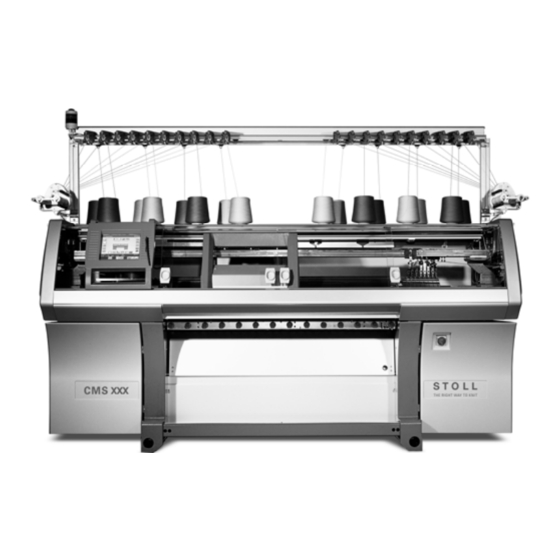
Page 25: Main Components Of The Knitting Machine
Main components of the knitting machine Front side 3.1 3 Main components of the knitting machine 3.1 Front side Fig. 3-1 Front view of the knitting machine Designation Designation Signal light (green,yellow) Engaging rod (red) Yarn control equipment Fabric take-down (main take- down, auxiliary take-down, take- down comb) Bobbin board (with yarn bobbin) 11... - Page 26 Main components of the knitting machine 3.1 Front side Inner view Fig. 3-2 Inner view of the knitting machine Designation Designation Carriage Yarn carrier Front needle bed Yarn carrier rod Left clamping and cutting bed...
-
Page 27: Lateral View (Right)
Main components of the knitting machine Lateral view (right) 3.2 3.2 Lateral view (right) Fig. 3-3 Right lateral view Designation Designation Yarn control device Lateral yarn tensioner Yarn feeding and control device 5 Lateral protective cover Friction feed wheel... -
Page 28: Rear Side
Main components of the knitting machine 3.3 Rear side 3.3 Rear side Fig. 3-4 Rear side (without rear panel segments) Designation Designation Rear needle bed Trailing cable (energy chain) Carriage Transformer (Fuses) Fluff absorption Control unit on the right Left control unit Main drive... -
Page 29: Optical And Acoustic Signal Elements
Main components of the knitting machine Optical and acoustic Signal elements 3.4 3.4 Optical and acoustic Signal elements The knitting machine control constantly controls the yarn, the fabric, all movable parts of machine, the motors and the electronic components. If an error occurs, the machine stops. -
Page 30: Touch Screen
Main components of the knitting machine 3.4 Optical and acoustic Signal elements 3.4.2 Touch screen The most common error causes are shown in the pictographs on the touch screen. If an error occurs, one pictograph appears (on a yellow background), and in the case of several errors the corresponding pictographs appear consecutively. -
Page 31: Horn
Main components of the knitting machine Optical and acoustic Signal elements 3.4 Pictographs Needle stop left Needle stop centre Needle stop right Piece counter Miscellaneous causes for stoppage Tab. 3-2 Pictographs for the display of stoppages 3.4.3 Horn A signal tone is produced in the following situations: if the machine stops because of an error approx. - Page 32 Main components of the knitting machine 3.4 Optical and acoustic Signal elements...
-
Page 33: Assembly And Setting Up
Assembly and setting up Preparing assembly 4.1 4 Assembly and setting up 4.1 Preparing assembly 4.1.1 Preparing installation location Installation location The installation location of the knitting machine must fulfill the following conditions: flat, firm surface in a building sufficient space between the knitting machines for Operating the machine Removing the fabric pieces from the machine do not put up the machine underground... -
Page 34: Assembling Machine
Assembly and setting up 4.2 Assembling machine 4.2 Assembling machine 4.2.1 Putting up knitting machine Lift the knitting machine with a ground conveyor (e.g. forklift) and transport In this case the following things have to be taken care of: The position of the centre of gravity is indicated on the front traverse (carriage in left transport position). - Page 35 Assembly and setting up Assembling machine 4.2 7. Remove side walls (3), spacer (5) (for component type 000) and transport flaps (4) on both machine sides. Fig. 4-2 Assemble transport flap (4) 8. sides (3) on both sides. 9. Remove all transport locks.
- Page 36 Assembly and setting up 4.2 Assembling machine Fig. 4-3 Fixing spots for transport locks Transport lock for: Carriage Touch screen (not for CMS 420 E) Drive Left and right protective hoods (CMS 420 E: right protective hood only) Cover at take-down comb Comb take-down (2 pieces for CMS 7xx and CMS 8xx) Touch screen (CMS 420 E, type 579)
-
Page 37: Connect The Knitting Machine
EN 60204-1, paragraph 4.3.1. In case of queries, please call the STOLL Helpline. Mains voltage 400 V The machine is set for a mains voltage of 400 V as standard. If there is another mains voltage, then a series transformer is to be used. - Page 38 Assembly and setting up 4.2 Assembling machine Connect mains supply to the main switch The knitting machine must be connected in the clockwise phase sequence. The mains supply is either led from the floor (1) to the main switch or from the ceiling (2) through the right support of the yarn feeding and control device to the main switch.
- Page 39 Assembly and setting up Assembling machine 4.2 DANGER High voltage! Electrical shock may cause death or serious injuries. Interrupt the mains supply to the machine It is not sufficient to simply switch off the machine at the main switch! Swap the two phases of the mains supply. Adapting fluff absorption to mains frequency Depending on the mains frequency (50 Hz or 60 Hz), the fluff absorption...
-
Page 40: Connect The Knitting Machine (Component Types 000 And 001)
EN 60204-1, Para. 4.3.1. In case of queries, please call the STOLL Helpline. The knitting machine can be operated with various mains voltages. The Setting transformer and... - Page 41 Assembly and setting up Assembling machine 4.2 Setting transformer to mains voltage: 1. Check the mains voltage of building mains supply. Fig. 4-6 Remove the rear panel segments 2. Open the rear panel segments with the key from the enclosed accessories and take off the segments.
- Page 42 Assembly and setting up 4.2 Assembling machine Set the protective motor switch in accordance with the mains voltage: DANGER High voltage! Electrical shock may cause death or serious injuries. Deenergize building mains supply before opening the housing. 1. Open the mains switch housing. Fig.
- Page 43 Assembly and setting up Assembling machine 4.2 1. Determine the direction of rotation of the mains supply. DANGER High voltage! Electrical shock may cause death or serious injuries. Deenergize building mains supply. 2. Open the mains switch housing. Potential equalization missing! Serious errors or disturbances can be caused in the machine and the electronic circuit if the terminal "PE "is not connected.
- Page 44 Assembly and setting up 4.2 Assembling machine Depending on the mains frequency (50 Hz or 60 Hz), the fluff absorption Adapting fluff absorption to operates with or without sealing plugs. mains frequency Fig. 4-10 Adapting fluff absorption (on the left: from component type 001 on, on the right:component type 000) The fluff absorption can be damaged if the mains frequency is not adapted!
-
Page 45: Aligning Knitting Machine
Assembly and setting up Assembling machine 4.2 4.2.4 Aligning knitting machine Align the machine: 1. Lay the level on the support surface on the right-hand side of the needle bed. Fig. 4-11 Right support surface for level 2. Align the knitting machine with the grub screws from the enclosed accessories. - Page 46 Assembly and setting up 4.2 Assembling machine 4. Call up "Manual interventions" window Fig. 4-13 "Manual interventions" window 5. Tap "Rel. drive brake" key. 6. Push the carriage to the right by hand until the support surfaces on the left side of the needle bed are accessible. 7.
-
Page 47: Mounting Yarn Feeding And Control Device
Assembly and setting up Mounting yarn feeding and control device 4.3 4.3 Mounting yarn feeding and control device When setting up the yarn feeding and control device, the following components are assembled: Yarn control device Signal lamp 4.3.1 Mount the yarn control device Push the supports of the yarn control device upward together with another mechanic to prevent the supports from jamming. - Page 48 Assembly and setting up 4.3 Mounting yarn feeding and control device Fig. 4-16 Position of supports for the yarn control device 5. Release the screw (2) on the left and right-hand sides of the machine, fold down the track (3) and tighten the screw (2) again. 6.
-
Page 49: Mounting Signal Lamp
Assembly and setting up Mounting yarn feeding and control device 4.3 4.3.2 Mounting signal lamp The power supply for the yarn control devices and the signal lamp are moved into the supports when the knitting machine is shipped. The signal lamp from the accessories needs only be connected and screwed into place. -
Page 50: Glue On Measuring Tape
4.5 Switching on machine 1. Turn the main switch on the front of the machine to "1". The STOLL logo is displayed. As soon as the machine is ready, the "BootOkc" window appears. 2. To begin production without changing the basic settings, tap the "Warm start"... -
Page 51: How To Bring The Carriage To An Immediate Standstill
Assembly and setting up How to bring the carriage to an immediate standstill 4.6 4.6 How to bring the carriage to an immediate standstill In order to stop the movement of the carriage immediately, carry out one of the following functions: Press the (1)engaging rod downward. -
Page 52: Checking Safety Equipment
Assembly and setting up 4.7 Checking safety equipment 4.7 Checking safety equipment The safety devices must be checked at least once every 24 hours: DANGER Defective safety device! Death or serious injury. If a safety device does not stop the machine, it must be stopped for safety reasons and secured against being started up again. - Page 53 Assembly and setting up Checking safety equipment 4.7 Safety device Checking Engaging rod (1) Production setting Pull engaging rod to highest position and release. The carriage pulls out. The engaging rod is held by a magnet. Press engaging rod to bottom position (zero position).
- Page 54 Assembly and setting up 4.7 Checking safety equipment Drive limit switch Call up the "Reference runs" window from the main menu and tap the "S<" key. Pull engaging rod to highest position. The carriage moves towards left. The machine must stop shortly before reaching the buffer.
Need help?
Do you have a question about the CMS 933 and is the answer not in the manual?
Questions and answers