Stoll CMS 530 Instruction Manual
Hide thumbs
Also See for CMS 530:
- Instruction manual (54 pages) ,
- Operating instructions manual (562 pages)

Subscribe to Our Youtube Channel
Related Manuals for Stoll CMS 530


Summary of Contents for Stoll CMS 530
- Page 1 Instruction manual for a safe operation of the knitting machine Type Computer type Component type CMS 530 OKC5.0 CMS 520 C OKC5.0 CMS 520 C+ OKC5.0 CMS 502 OKC5.0 ID 267 886...
- Page 2 Translation of the original operating instructions Operating system of the machine: V_OKC_005.000.000_STOLL (or higher) H. STOLL GmbH & Co. KG, Stollweg 1, D-72760 Reutlingen, Germany Our products are being developed further continuously. They are therefore subject to technical modifica- tions.
-
Page 3: Table Of Contents
Table of Contents 1 Documentation DVD 2 Safety instructions 2.1 Intended use ........................ 6 2.2 Organizational measures..................... 7 2.3 Personnel qualifications and selection................. 8 2.3.1 Personnel qualification .................... 8 2.3.2 Selection of personnel .................... 9 2.4 Symbols in this document.................... 10 2.5 Warning .......................... - Page 4 6 Optical and acoustic signal elements ............... 38 6.1 Signal light ......................... 38 6.2 Touch screen ........................ 39 6.3 Horn ........................... 40 6.4 Lamps on the yarn control device.................. 41 7 Assembly and setting up .................. 42 7.1 Preparing assembly ...................... 42 7.1.1 Preparing installation location...................
-
Page 5: Documentation Dvd
Documentation DVD 1 Documentation DVD Documentation DVD Included in the accessories you will find a DVD with documents about your machine. ◆ Operating instructions ◆ Safety instructions ◆ Spare Parts Catalog ◆ Circuit diagram ◆ Brochure "Cleaning, maintenance, care" ◆ Pocket Card ◆... -
Page 6: Safety Instructions
The translations are carried out very carefully. Should you have any doubts about the accuracy of the translation, please compare this with the accompanying original document. In case of queries, please call the Stoll Helpline. Additional information is available via: ... -
Page 7: Organizational Measures
No modifications, additions or conversions may be made on the machine that are not authorized by Stoll. Use only the original Stoll spare parts during repairs and maintenance. No arbitrary changes are to be made in the program in the operating system of the computer, the machine software and the controlling system/ controls. -
Page 8: Personnel Qualifications And Selection
Safety instructions Personnel qualifications and selection 2.3 Personnel qualifications and selection Any work on and with the machine must be executed by reliable personnel only. Observe the country-specific laws and regulations. Personnel qualification 2.3.1 Personnel qualification In order that the knitting machine can be operated correctly and safely, it must be set up and operated by reasonably skilled (qualified) personnel: ... -
Page 9: Selection Of Personnel
Safety instructions Personnel qualifications and selection Knitting expert A knitting expert will be considered a person who can assess and execute the jobs assigned to him and can identify possible dangers. The expert possesses the following characteristics: technical qualification on the knitting machine and the pattern design system ... -
Page 10: Symbols In This Document
Safety instructions Symbols in this document 2.4 Symbols in this document Symbols in this document Some information in this document are marked with special symbols to make it easier to access this information quickly. The additional equipment of your machine can deviate from this description depending on the machine type (type of machine, scope of supply, special equipment). -
Page 11: Warning
Safety instructions Warning 2.5 Warning In this chapter you will find explanations to the warnings on the machine and in the documentation. Warnings used 2.5.1 Warnings used Warnings on the machines correspond to the standard ISO 3864-2. Scope of validity: all countries except USA and Canada A warning as per ISO 3864-2 can comprise of the following elements: Elements of a warning Pictograph... - Page 12 Safety instructions Warning List of warnings on the Warnings have to be maintained in a complete and machine legible condition at all times. The order numbers of the labels are found in the following table. List of warnings Warning Explanation Warning on the rear panel ID 244 266 Warning on the friction feed wheel...
-
Page 13: Explanation To The Pictogram (Iso)
Safety instructions Warning 2.5.2 Explanation to the pictogram (ISO) Explanation to the pictogram (ISO) Pictograms on the machine Pictographs used on the knitting machine Type Pictograph Explanation Warning General warning indication indication Dangerous electrical voltage Danger of crushing and cutting Danger from flying-off mechanical parts or lubricating materials Danger of suction... - Page 14 Safety instructions Warning Type Pictograph Explanation Command Wear safety glasses Disconnect mains supply Wear hair protection gear Wait till all LEDs on the control cabinet are Pictographs used on the knitting machine Warnings in the documentation...
-
Page 15: Warnings In The Documentation
Safety instructions Safety precautions regarding the machine's life phases 2.5.3 Warnings in the documentation The warnings in the documentation have the following structure: Safety sign The safety sign warns about the danger of injury and death. In order to avoid death and injuries, all measures that are indicated along with the safety sign are to be followed. -
Page 16: Safety Precautions Regarding The Machine's Life Phases
Safety instructions Safety precautions regarding the machine's life phases 2.6 Safety precautions regarding the machine's life phases Avoid any operational mode that might be prejudicial to safety. Take the necessary precautions to ensure that the machine is used only when in a safe and reliable state. -
Page 17: Safety Instructions For Installing
We advise you with emphasis to the fact that the Co. H. Stoll GmbH & Co. KG will take no guarantee or responsibility for damages in this conjunction. For further enquiries... -
Page 18: Safety Precautions For Production
Observe the country-specific laws and regulations. Observe the manufacturer's specifications (safety data sheet). For any further queries please contact Stoll. Fire hazard by fluff, dust and Fluff, dust and other impurities to be removed other impurities. regularly from the entire machine depending... -
Page 19: Additional Safety Instructions For The Operation With Open Covers
Safety instructions Safety precautions regarding the machine's life phases 2.6.6 Additional Safety Instructions for the Operation with Additional Safety Instructions for the Operation with Open Covers Open Covers If the covers are open the engaging rod cannot be locked into it's highest position (production). -
Page 20: Safety Instructions For Lubrication, Cleaning And Maintenance
Safety instructions Safety precautions regarding the machine's life phases 2.6.7 Safety Instructions for Lubrication, Cleaning and Safety Instructions for Lubrication, Cleaning and Maintenance Maintenance Type of risks Measures Danger of crushing and cutting by the Switch off machine at main switch. carriages, racking, the needle beds, Secure the machine against being the clamping and cutting devices. -
Page 21: Safety Instructions For The Repair
Safety instructions Safety precautions regarding the machine's life phases 2.6.8 Safety instructions for the repair Safety instructions for the repair Danger by mechanical parts Danger by mechanical parts Reason Measures Danger of injury by rotating or Do not reach into the running machine. moving parts. - Page 22 Safety instructions Safety precautions regarding the machine's life phases Danger by electrical energy Danger by electrical energy Reason Measures Danger to life by electrical shock Work is to be done only by an during work on the electrical electrician. assembly of the machine. Switch off machine.
- Page 23 Safety instructions Safety precautions regarding the machine's life phases Reason Measures Environment pollution is caused if Ensure that all consumables and the disposal of replaced parts and of replaced parts are disposed of safely consumables is not done and with minimum environmental professionally.
- Page 24 Safety instructions Safety precautions regarding the machine's life phases Pictograph Safety precautions and protective measures Batteries are sensitive to mechanical damages. Handle with care. Danger of short circuit. The contacts of the battery are always under tension, therefore, do not place foreign objects or tools on the battery.
-
Page 25: Safety Instructions For Dismantling Work (Dismantling)
Safety instructions Safety precautions regarding the machine's life phases 2.6.9 Safety instructions for dismantling work (dismantling) Dismantling for a longer Type of risks Measures storage or for evacuation Danger to life because of electrical Get the machine disconnected from shock during work on the electrical the mains supply by an electrician. -
Page 26: Electrical Data Of The Machine
CMS 803 1640 CMS 730 T k&w 1510 CMS 730 S k&w 1520 CMS 530 T 58,5 1260 CMS 530 MT B 58,5 1260 CMS 530 58,5 1240 CMS 520 C, CMS 520 C+ 58,5 1250 Dimensions, weight and dynamic weight... - Page 27 Electrical data of the machine Electrical data CMS 502 Machine dimensions (in cm) Machine dimensions (in cm) A Width B Depth C Height D Spacing of set screws E Nominal working width The back-and-forth movement of the carriage causes the dynamic loads listed above to occur at the set screws.
-
Page 28: Electrical Data
If the knitting machine is operated with a generator, make sure that the voltage supplied by the generator meets the requirements of the EN 60204-1, Parag. 4.3.1. In case of queries, please call the Stoll Helpline. Gauge ranges... -
Page 29: Gauge Ranges
Electrical data of the machine Operating conditions 3.3 Gauge ranges Number of needles per needle bed Gauge Area Needle number Nominal width: Nominal width: Nominal width: Nominal width: Nominal width: Nominal width: 114 cm (45") 127 cm (50") 183 cm (72") 213 cm (84") 218 cm (86") 244 cm (96") -
Page 30: Operating Conditions
When yarns are being processed, electrostatic charges can be produced if the relative humidity is not at least 50 % In the case of deviating operating conditions please contact Stoll helpline. Storage conditions 3.5 Storage conditions If the knitting machine is to be stored for a longer period of time the following tasks must be carried out: 1. -
Page 31: Noise Emissions
The measuring has been performed on a representative basis for the series CMS 5xx HP on a CMS 530 HP E7.2. The machines of the CMS 5xx HP series emit a sound pressure level which is not higher than the specified values under comparable conditions. -
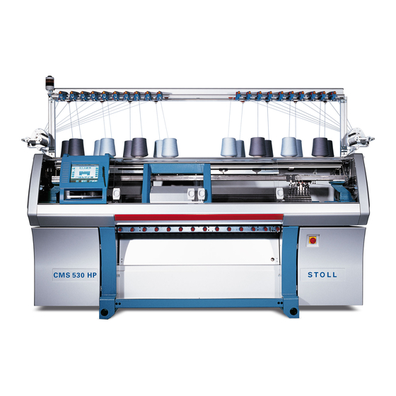
Page 32: Main Components Of The Knitting Machine
Main components of the knitting machine Front side 4 Main components of the knitting Main components of the knitting machine machine Front side 4.1 Front side Front view of the knitting machine Front view of the knitting machine Label Label Signal light (green, yellow) Engaging rod (red) Yarn control units... - Page 33 Main components of the knitting machine Front side Inner view Inner view of the knitting machine Inner view of the knitting machine No. Label Label Carriage Yarn Carrier Front needle bed Yarn carrier rod Left clamping and cutting bed...
-
Page 34: Lateral View (Right)
Main components of the knitting machine Lateral view (right) 4.2 Lateral view (right) Lateral view (right) Right lateral view Right lateral view Label Label Yarn control unit Lateral yarn tensioner Yarn guide device Lateral safety door Friction feed wheel... -
Page 35: Rear Side
Main components of the knitting machine Rear side 4.3 Rear side Rear side Rear side (without rear panel segments) Rear side (without rear panel segments) Label Label Carriage Fluff absorption Rear Needle Bed Control unit on the right Trailing cable (energy chain) 7 Main drive Transformer (Fuses) Racking device... -
Page 36: Security Relevant Operating Elements
Security relevant operating elements Main switch 5 Security relevant operating Security relevant operating elements elements Main switch 5.1 Main switch Main switch (5xx) Main switch Main switch The main switch (1) is located on the front of the machine above the right control unit. -
Page 37: Engaging Rod
Security relevant operating elements Engaging rod 5.2 Engaging rod Engaging rod Positions of the engaging rod 5xx Engaging rod Engaging rod 1 Carriage stopped 2 reduced speed 3 normal speed The carriage assembly, and therefore also knitting, is started and stopped with the engaging rod. -
Page 38: Optical And Acoustic Signal Elements
Optical and acoustic signal elements Signal light 6 Optical and acoustic signal Optical and acoustic signal elements elements The knitting machine control constantly controls the yarn, the fabric, all movable parts of machine, the motors and the electronic components. If an error occurs, the machine stops. -
Page 39: Touch Screen
Optical and acoustic signal elements Touch screen 6.2 Touch screen Touch screen The most common error causes are shown in the pictographs on the touch screen. If an error occurs, one pictograph appears (on a yellow background), and in the case of several errors the corresponding pictographs appear consecutively. -
Page 40: Horn
Optical and acoustic signal elements Horn Pictographs Belt take-down Friction feed wheel on Friction feed wheel on the left the right Greasing (ultra coarse Front racking Lubrication machine) Rear racking Power failure Needle stop left Needle stop centre Needle stop right Piece counter miscellaneous causes of stop motion... -
Page 41: Lamps On The Yarn Control Device
Optical and acoustic signal elements Lamps on the yarn control device 6.4 Lamps on the yarn control device Lamps on the yarn control device Lamps on the yarn control device Lamps on the yarn control device In the case of a yarn breakage or yarn end, the yarn break control of the yarn control device switches off the knitting machine. -
Page 42: Assembly And Setting Up
Assembly and setting up Preparing assembly 7 Assembly and setting up Assembly and setting up Preparing assembly 7.1 Preparing assembly Preparing installation location 7.1.1 Preparing installation location Installation location The installation location of the knitting machine must fulfill the following conditions: ... -
Page 43: Transporting Machine To Installation Location
Assembly and setting up Assembling machine 7.1.3 Transporting machine to installation location Transporting machine to installation location DANGER Heavy knitting machine! Danger of injury for persons and damage of the knitting machine. ➜ Country-specific regulations for the prevention of industrial accidents for the transport of heavy loads are to be observed. -
Page 44: Assembling Machine
Assembly and setting up Assembling machine 7.2 Assembling machine Putting up knitting machine 7.2.1 Putting up knitting machine Lift the knitting machine with a ground conveyor (e.g. fork lift) and transport it. In this case the following things have to be taken care of: ... - Page 45 Assembly and setting up Assembling machine 2. Lift the knitting machine with a fork lift from the transport surface. 3. Bring the knitting machine to the site of installation. 4. Lay Washers (1) from the accessories under the knitting machine foot. Place the washers in such a manner that the cavity comes exactly under the grub screw (2).
- Page 46 Assembly and setting up Assembling machine 8. Swivel the cover of the control unit outwards. In the case of the CMS 502, remove the cover. 9. Remove the transport flap (4). In the case of the CMS 502, the steps 10 to 13 are not necessary.
- Page 47 Assembly and setting up Assembling machine Fixing spots for transport locks Fixing spots for transport locks Transport lock for: Carriage Cover at comb take-down Touch screen Comb Take-down Drive Comb take-down (2 pieces for CMS 7xx and CMS 8xx) Left and right cover Preserve the transport locks.
-
Page 48: Connecting The Knitting Machine (Mains Voltage 230 V)
If the knitting machine is operated with a generator, make sure that the voltage machine with a generator supplied by the generator meets the requirements of the EN 60204-1, Parag. 4.3.1. In case of queries, please call the Stoll Helpline. Connect mains supply Connect mains supply DANGER Life-threatening high voltage! Electrical shock may cause death or serious injuries. - Page 49 Assembly and setting up Assembling machine How to connect the mains supply: The main switch is switched off ("0") The mains supply to the machine is unplugged (currentless) DANGER Life-threatening high voltage! Electrical shock may cause death or serious injuries. ➜...
- Page 50 Assembly and setting up Assembling machine 3. Open the plug (2) and connect to the mains supply (3a) or·(3b) Mains Mains supply (3b) Example for mains symmetry supply (3a) Connection variant Plug (2) L2 * L2 ** L3 ** L1 ** L3 * L3 ** L1 ** L2 ** * L2 and L3 are not used internally in the machine.
- Page 51 Assembly and setting up Assembling machine 7. Open the main switch. For this, loosen the 4 screws and remove the cover of the main switch. 8. Connect the plug (4) on the right side. 9. Close the main switch. 10. Close the cover at the right control cabinet again. Adapting fluff absorption to mains frequency...
- Page 52 Assembly and setting up Assembling machine Adapting fluff absorption to Depending on the mains frequency (50 Hz or 60 Hz), the fluff absorption mains frequency operates with or without sealing plugs. Adapting fluff absorption Adapting fluff absorption The fluff absorption can be damaged if the mains frequency is not adapted! The fluff absorption is overloaded if it is not adapted to the mains frequency.
-
Page 53: Connecting The Knitting Machine (Mains Voltage 400 V)
If the knitting machine is operated with a generator, make sure that the voltage machine with a generator supplied by the generator meets the requirements of the EN 60204-1, Parag. 4.3.1. In case of queries, please call the Stoll Helpline. Connect mains supply DANGER Life-threatening high voltage! Electrical shock may cause death or serious injuries. - Page 54 Assembly and setting up Assembling machine Connect mains supply How to connect the mains supply: The main switch is switched off ("0") The mains supply to the machine is unplugged (currentless) DANGER Life-threatening high voltage! Electrical shock may cause death or serious injuries. ➜...
- Page 55 Assembly and setting up Assembling machine 3. Open the plug (2) and connect to the mains supply (3). Mains supply (3) Example for mains symmetry Connection variant Plug (2) L3 * L3 ** L1 ** L2 ** N ** N ** N ** * L3 is not used internally in the machine.
- Page 56 Assembly and setting up Assembling machine 7. Open the main switch. For this, loosen the 4 screws and remove the cover of the main switch. 8. Remove the plug (4) from the left side and connect it on the right side. 9.
- Page 57 Assembly and setting up Assembling machine Adapting fluff absorption to Depending on the mains frequency (50 Hz or 60 Hz), the fluff absorption mains frequency operates with or without sealing plugs. Adapting fluff absorption Adapting fluff absorption The fluff absorption can be damaged if the mains frequency is not adapted! The fluff absorption is overloaded if it is not adapted to the mains frequency.
-
Page 58: Connecting The Knitting Machine (Mains Voltage 230 V / 120 V, "Phase-Phase")
If the knitting machine is operated with a generator, make sure that the voltage machine with a generator supplied by the generator meets the requirements of the EN 60204-1, Parag. 4.3.1. In case of queries, please call the Stoll Helpline. Connect mains supply Connect mains supply DANGER Life-threatening high voltage! Electrical shock may cause death or serious injuries. - Page 59 Assembly and setting up Assembling machine How to connect the mains supply: The main switch is switched off ("0") The mains supply to the machine is unplugged (currentless) DANGER Life-threatening high voltage! Electrical shock may cause death or serious injuries. ➜...
- Page 60 Assembly and setting up Assembling machine 3. Open the plug (2) and connect to the mains supply (3). Mains supply (3) Example for mains symmetry Connection variant Plug (2) A 4. Make sure that the operational mains supply is loaded evenly (mains symmetry).
- Page 61 Assembly and setting up Assembling machine 7. Open the main switch. For this, loosen the 4 screws and remove the cover of the main switch. 8. Connect the plug (4) on the left side. 9. Close the main switch. 10. Close the cover at the right control cabinet again. Adapting fluff absorption to mains frequency...
- Page 62 Assembly and setting up Assembling machine Adapting fluff absorption to Depending on the mains frequency (50 Hz or 60 Hz), the fluff absorption mains frequency operates with or without sealing plugs. Adapting fluff absorption Adapting fluff absorption The fluff absorption can be damaged if the mains frequency is not adapted! The fluff absorption is overloaded if it is not adapted to the mains frequency.
-
Page 63: Plug In Battery Pack
The main switch is switched off. 1. Open the cover on the control unit. CMS 530 CMS 520 C CMS 502 CMS ADF-3 CMS 530 MT B CMS 530 T CMS 730 S CMS 730 T CMS 803 CMS 822... -
Page 64: Mounting The Yarn Guide Device
Assembly and setting up Assembling machine 7.2.6 Mounting the yarn guide device Push the supports of the yarn guide device upward together with another mechanic to prevent the supports from jamming. The main switch is set to "0" and secured against being switched on again. 1. - Page 65 Assembly and setting up Assembling machine Mounting the rear track of the The additional equipment of your machine can deviate from this description yarn guide device and the depending on the machine type (type of machine, scope of supply, special additional bobbin boards equipment).
-
Page 66: Mounting Signal Light
Assembly and setting up Assembling machine 7.2.7 Mounting signal light The power supply for the yarn control devices and the signal light are moved into the supports when the knitting machine is shipped. The signal light from the accessories needs only be connected and screwed into place. Signal light Signal light Carefully tighten the fastening screw of the signal light to... -
Page 67: Mounting Friction Feed Wheel
Assembly and setting up Assembling machine 7.2.8 Mounting friction feed wheel Depending on the machine type, the friction feed wheel is already mounted. Mounting friction feed wheel: 1. Screw the friction feed wheel on the holder. Mounting the friction feed wheel Mounting the friction feed wheel DANGER Life-threatening high voltage! -
Page 68: Set Date And Time
Assembly and setting up Assembling machine 7.2.9 Set date and time Set date and time 1. Switch on main switch. 2. The "BootOKC" window appears and simultaneously also a message indicating that time and date are not correct. 3. Tap the "OK" key. 4. -
Page 69: Aligning Knitting Machine
Assembly and setting up Assembling machine 7.2.10 Aligning knitting machine Keys for aligning the machine Function Call up the "Service" menu Call up "Reference runs" window Call up "Main menu" 1. Turn the main switch at the front of the machine to 1. 2. - Page 70 Assembly and setting up Assembling machine 7. If the left edge of the carriage (1) is within the needle bed, press the engaging rod downwards. Carriage in the needle bed position (the covers were opened for a better overview) "Carriage in the needle bed" position (the covers were opened for a better overview) 8.
- Page 71 Assembly and setting up Carry out the reference run 11. Lay the spirit level on the support surface on the right-hand side of the needle bed. Right support surface for the spirit level (on the right: CMS 502) Right support surface for the spirit level (on the right: CMS 502) 12.
-
Page 72: Carry Out The Reference Run
Assembly and setting up Carry out the reference run 7.3 Carry out the reference run The position of the carriage towards the needles is determined during the reference run. Keys for carrying out the reference run Function Call up the "Service" menu Call up "Reference runs"... -
Page 73: Glue On Measuring Tape
Assembly and setting up Glue on measuring tape 5. The reference run is complete, the machine is ready to knit. The carriage is positioned at the right position for you to be able to load a knitting program. Call up "Main menu". Leave the machine switched on for at least 6 hours in order to charge the accumulators fully. -
Page 74: How To Bring The Carriage To An Immediate Standstill
Assembly and setting up Checking protective devices 7.5 How to bring the carriage to an immediate standstill In order to stop the movement of the carriage immediately, carry out one of the following functions: 1. Press the engaging rod (1) downward. 2. -
Page 75: Checking Protective Devices
Assembly and setting up Checking protective devices 7.6 Checking protective devices The protective devices must be checked at least once every 24 hours: DANGER Defective protective device! Death or serious injury. ➜ If a protective device does not stop the machine, it must be stopped for safety reasons and secured against being started up again. - Page 76 Assembly and setting up Checking protective devices Protective device Checking Engaging rod(1) Production setting ◆ Pull engaging rod to highest position and release. The carriage pulls out. The engaging rod is held by a magnet. ◆ Press engaging rod to bottom position (zero position).
- Page 77 Assembly and setting up Checking protective devices Protective device Checking Limit switch drive Check if the left and right end stops for the carriage have the correct position and if they are damaged. only with older machines (before August 2013): ◆...
- Page 78 Assembly and setting up Checking protective devices Protective device Checking ◆ Machine with comb Pull engaging rod to highest position and release. take-down: The carriage pulls out. Comb safety door (5) ◆ Slide the comb safety door to the left. A recessed grip is located on the right-hand side of the comb cover plate.
- Page 79 Assembly and setting up Checking protective devices...
Need help?
Do you have a question about the CMS 530 and is the answer not in the manual?
Questions and answers