Table of Contents
Advertisement
Quick Links
Advertisement
Table of Contents

Subscribe to Our Youtube Channel
Related Manuals for Wood-mizer EG800EH40S


Summary of Contents for Wood-mizer EG800EH40S
- Page 3 Wood-Mizer ® Edger Safety, Operation, Maintenance and Replacement Parts EG800EH40S rev. A2.00 Safety is our #1 concern! Read and understand all safety information and instructions before operating, setting up and/or maintaining this machine. Form #810 This is the original language...
-
Page 4: Table Of Contents
Table of Contents Section-Page SECTION 1 SERVICING THE EDGER Safety & General Information ..............1-1 If You Need To Order Parts ..............1-1 Customer and Edger Identification............1-1 If You Need Service ................1-2 EG800 Edger Components ..............1-3 SECTION 2 SAFETY Safety Symbols..................2-1 Safety Instructions ..................2-1 SECTION 3 Operation ....................3-2 Pre-Operation Check ................3-2... - Page 5 General Contact Information Getting Service Wood-Mizer is committed to providing you with the latest technology, best quality and strongest customer service available on the market today. We continually evaluate our customers’ needs to ensure we’re meeting current wood-processing demands. Your comments and suggestions are welcome.
- Page 6 Branches & Authorized Sales CentersWood-Mizer Locations (North and South America) Branches & Authorized Sales CentersWood-Mizer Locations (North and South America) EUROPE UNITED STATES European Headquarters World Headquarters Wood-Mizer Industries Sp. z o.o. Wood-Mizer LLC Nagórna 114, 62-600 Koło, Poland 8180 West 10th Street Tel.: +48-63-26-26-000 Indianapolis,Indiana 46214-2400, Fax: +48-63-27-22-327 www.woodmizer.eu...
- Page 7 Branches & Authorized Sales CentersWood-Mizer Locations (North and South America) CROATIA Krešimir Pregernik ITALY Pasquale Felice SERBIA Dragan Markov Pregimex d.o.o. Wood-Mizer Italia Srl Wood-Mizer Balkan d.o.o. S. Batušiæa 31, 10090 Zagreb Cda. Capoiaccio SN Svetosavska GA 3/3; P. Fah 25 Tel.:/Fax: +3851-38-94-668...
- Page 8 Brazil Headquarters Europe Headquarters Serving Brazil Serving Europe, Africa, West Asia Wood-Mizer do Brasil Wood-Mizer Industries Sp z o.o. Rua Dom Pedro 1, No: 205 Bairro: Sao Jose Nagorna 114 Ivoti/RS CEP:93.900-000 62-600 Kolo, Poland Tel: +55 51 9894-6461/ +55 21 8030-3338/ +55 51 Phone: +48.63.26.26.000...
-
Page 9: Servicing The Edger
Day shipping are available at additional cost. Customer and Edger Identification Each Wood-Mizer Edger has its own serial number. In addition, when you pick up your edger, you will receive a customer number. These two numbers will help expedite our service to you. Please locate them now and write them below so you have quick, easy access to them. -
Page 10: If You Need Service
Servicing The Edger If You Need Service See Figure 1-1 An identification plate of the E100 Edger is described below. Type Production Date Revision Number Supply Voltage Total Weight Motor Rotational Speed Rated Power and Current Intensity Serial No. FIG. 1-1 See Figure 1-2 See the following figures for the serial number location. -
Page 11: Eg800 Edger Components
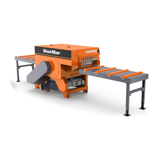
Servicing The Edger EG800 Edger Components EG800 Edger Components See Figure 1-3 The major components of the EG800 Edger are shown below. Outfeed Table Motor/ Engine Infeed Table Sawdust Removal Belt (Option) Blade Roller Motor FIG. 1-3 EG800 Servicing The Edger EGdoc031120... -
Page 12: Safety
Safety Safety Symbols SECTION 2 SAFETY Safety Symbols The following symbols and signal words call your attention to instructions concerning your personal safety. Be sure to observe and follow these instructions. DANGER! indicates an imminently hazardous situation which, if not avoided, will result in death or serious injury. - Page 13 It is always owner's responsibility to comply with all applicable federal, state and local laws, rules and regulations regarding the ownership and operation of your Wood-Mizer Edger. All Wood-Mizer owners are encouraged to become thoroughly familiar with these applicable laws and comply with them fully while using the Edger.
- Page 14 Safety Keep Edger and Area Around Edger Clean Keep Edger and Area Around Edger Clean DANGER! Maintain a clean and clear path for all necessary movement around the Edger and lumber stacking areas. Failure to do so may result in serious injury. Dispose of sawing by-products properly IMPORTANT! Always properly dispose of all sawing by-products,...
- Page 15 Safety Keep Persons Away Keep Persons Away DANGER! Keep all persons out of the path of moving equipment and boards when operating the Edger. Failure to do so may result in serious injury. Keep Hands Away DANGER! Engine components can become very hot during operation.
- Page 16 Safety Use Proper Maintenance Procedures WARNING! Kickback hazard. Stay clear of area during operation. Follow all anti-kickback service and safety rules. Failure to do so may result in serious injury. DANGER! Before changing the blades or performing any service to the machine, disconnect the power cord from the electric box.
- Page 17 Always be sure that all safety warning decals are clean and readable. Replace all damaged safety decals to prevent personal injury or damage to the equipment. Contact Wood-Mizer Customer Service or the Wood-Mizer distributor in your area to order a new decal. IMPORTANT!
- Page 18 Safety Safety Labels Description Safety Labels Description See table 2-1 See the table below for descriptions of the safety labels placed on the machine. TABLE 2-1 Decal View Decal No. Description 096317 CAUTION! Read thoroughly the operator’s manual before operating the Edger. Observe all safety instructions and rules when operating.
- Page 19 Safety Safety Labels Description TABLE 2-1 096319 Always disconnect the power cord before opening the electric box. 099540 CAUTION! Toothed gear - keep persons away! 099540 524992 Decal, kickback hazard warning (pictogram) S12004G Always wear safety goggles when operating the Edger. safety EGdoc031120...
- Page 20 Safety Safety Labels Description TABLE 2-1 S12005G Always wear protective ear muffs when operating the Edger. 501465 Always wear safety boots when operating the edger! 510080 Always wear protective gloves when operating the edger! 539211 Always wear protective apron when operating the edger! 501467 Lubrication point...
- Page 21 Safety Safety Labels Description TABLE 2-1 099504 Visible and/or invisible laser radiation. Avoid eye or skin exposure to direct or scattered radiation. 099504 P85070 CE safety certification 089296 Rotation direction 089296 S20097 Motor rotation direction. S20097 safety EGdoc031120 2-10...
- Page 22 SECTION 3 EGdoc031120 Obsługa maszyny...
-
Page 23: Operation
Operation Operation Pre-Operation Check Prior to operating the Edger; always perform these basic checks: 1. Make sure the Edger is level. Secure the edger to the ground. A concrete foundation and 12mm anchored bolts are recommended. CAUTION! Make sure the edger is level before operation. Failure to do so can and will affect machine operation and wear life. - Page 24 Pre-Operation Check FIG. 3-1 3. Be sure all guards and covers are in place and secured. DANGER! Make sure all guards and covers are in place and secured before operating or transporting the Edger. Failure to do so may result in serious injury.
- Page 25 Pre-Operation Check the infeed table, outfeed table and on the control panel. Emergency Stop Twist to release FIG. 3-2 EG800 EMERGENCY STOP LOCATION Obsługa maszyny EGdoc031120...
-
Page 26: Control Overview
Control Overview Control Overview Control Panel, EG800 See figure 3-3. The control panel includes: main switch (A), blade motor start-stop switch (B), power feed switch (C), feed rate knob (D) and emergency stop button (E). FIG. 3-3 SWITCHES ON THE CONTROL PANEL 1. -
Page 27: Edger Setup
Edger Setup 4. Feed Roller Speed Adjustment The feed roller speed switch controls the speed at which the feed roller moves. Turn the switch right to increase the speed, turn left to reduce the speed. 5. Emergency Stop Push the emergency stop button to stop the blade and the track feed motors. Turn the emergency stop clockwise to release the stop. - Page 28 Edger Setup 400 VAC C100 4 x16mm , up to 15 m long TABELA 3-1 IMPORTANT! It is required that a 30mA Ground Fault Interrupter (GFI) be used. IMPORTANT! When starting the machine for the first time, check that blade rotation direction is as indicated by the arrow located on the blades covers.
-
Page 29: Machine Start
Machine start Machine start DANGER! Before starting the machine, perform these steps to avoid injury and/or damage to the equipment: Close the blade housing covers and replace any guards removed for service. Check the infeed table and remove all loose objects such as tools, wood, etc. ... - Page 30 Machine start The motor should start. FIG. 3-6 SWITCHES ON THE CONTROL PANEL To stop the blade motor, press the STOP button shown on the figure above. The motor also may be stopped by pushing the emergency stop button. The speed at which the feed rollers move is adjustable by dial located on the control panel, allows the operator to adjust the feed rate from 0 to ca.
-
Page 31: Board Entry Cover Installation
Board entry cover installation Board entry cover installation Install board entry cover (A) to infeed table (B) using fasteners (C) listed in EG800 Replacement Parts #811 Cover) . See Section 2.9 Board Enter FIG. 3-7 Obsługa maszyny EGdoc031120 3-10... -
Page 32: Maintenance And Alignment
Maintenance and Alignment Rollers and Blades Cover SECTION 4 MAINTENANCE AND ALIGNMENT WARNING! Before performing service near moving parts such as blades, pulleys, motors, belts and chains, set the main switch in the "0" position and disconnect the power cord. WARNING! Always shut off the motor and allow all moving parts to come to a complete stop before removing any guards or covers. -
Page 33: Replacing And Aligning The Blades
Maintenance and Alignment Replacing and Aligning the Blades 2. Move the blade housing (B) to access the blades and rollers. FIG. 4-1 Replacing and Aligning the Blades Replace the blades as necessary. Dull blades will cause the motors to work harder and will result in decreased cut quality and accuracy. - Page 34 Maintenance and Alignment Replacing and Aligning the Blades 2. Remove bolts (A) and dismount the blade drive shaft cover (B) to access the blades. FIG. 4-2 See Figure 4-3. 3. Place the provided wrench (A) on the blade drive shaft (B). Place the second wrench (also provided) on the nut (C), loosen and remove this nut to get access to spacers (D) and blades (E).
-
Page 35: Tensioning The Chains And Belts
Maintenance and Alignment Tensioning the Chains and Belts See Figure 4-4. Mount blades and arbor cover (B) using bolts (A). FIG. 4-4 4.3 Tensioning the Chains and Belts DANGER! Always shut off the motor and allow all moving parts to come to a complete stop before removing any guards or covers. - Page 36 Maintenance and Alignment Conveyor Belt Tensioning 1. Unbolt fasteners (A) and remove the guard (B) shown below. FIG. 4-5 See Figure 4-6. 2. Using the tensioner bolts (A), tension the conveyor belt evenly. FIG. 4-6 3. Reinstall the guard. EGdoc031120 Maintenance and Alignment...
- Page 37 Maintenance and Alignment Main Drive Belts 4.3.2 Main Drive Belts Check the main drive belts tension every 40 hours of operation. Adjust the belt if necessary. The belts should have approximately 15 mm of slack. See Figure 4-7. To adjust the main drive belts tension: ...
- Page 38 Maintenance and Alignment Roller Chain Tension See Figure 4-8. Be sure that motor pulley (A) and arbor pulley (B) are in line. FIG. 4-8 4.3.3 Roller Chain Tension Check that the rollers chain is tensioned properly every 100 hours of operation. Adjust the chain if necessary.
- Page 39 Maintenance and Alignment Roller Chain Tension 3. After tensioning chain, tighten the bolts (B. FIG. 4-9 Maintenance and Alignment EGdoc031120...
-
Page 40: Adjusting Height Of The Hold-Down Rollers
Maintenance and Alignment Adjusting Height of the Hold-Down Rollers 4.4 Adjusting Height of the Hold-Down Rollers See Figure 4-10. IMPORTANT! Be sure the dimensions in rollers lifter mechanism are as shown below. If not, adjust backlash A1 using nuts (A) to 20 mm and backlash B1 using nuts B to 10 mm. - Page 41 Maintenance and Alignment Adjusting Height of the Hold-Down Rollers See Figure 4-11. IMPORTANT! Space between rollers must be minimum 20 mm for boards up to 50mm and 50mm for boards from 50mm to 107mm. FIG. 4-11 Maintenance and Alignment EGdoc031120 4-10...
- Page 42 Maintenance and Alignment Adjusting Height of the Hold-Down Rollers See Figure 4-12. To adjust the rollers heigh: Adjust hold-down rollers (A) height by using (B) nuts. You can also use 10mm thick flat plates (C) to change the rollers height by 10mm. Push down ...
-
Page 43: Lubrication And Cleaning
Maintenance and Alignment Lubrication and cleaning 4.5 Lubrication and cleaning 1. Remove any debris from the blade drive shaft every 8 hours of operation. Use a soft cloth to apply a dry graphite daily to ensure resistance-free motion and to prevent surface corrosion. 2. -
Page 44: Maintaining The Anti-Kickback Fingers
Maintenance and Alignment Maintaining the Anti-Kickback Fingers Maintaining the Anti-Kickback Fingers This machine has the potential for kickbacks. Kickbacks can cause the board to be suddenly and uncontrollably hurled towards the operator. Such action can result in severe injury or death. If you are working with frozen boards or with boards that have protruding knots, the chance of kickbacks is increased. -
Page 45: Blade Sharpening
Maintenance and Alignment Blade Sharpening 4.7 Blade Sharpening The blade teeth should be sharpened as soon as their dullness, measured as shown in the figure on the right, is 0.10 -0.20 mm (0.0039 - 0.0078"). Use diamond grinding wheels for sharpening the blades. Apply intensive cooling during sharpening to prevent overheating and structural changes in the cemented carbide tips. -
Page 46: Safety Devices Inspection (Only Ce Version)
Maintenance and Alignment Safety Devices Inspection (Only CE Version) Do not operate the machine if either of the blades is dull. Using dull blades causes stronger cutting resistance, decreased cut accuracy and may result in blade burning and even cracks in the gullets and the wiper slots. - Page 47 Maintenance and Alignment Safety Devices Inspection (Only CE Version) E-Stop button circuit - infeed and outfeed table Safety switch circuit - cover Safety switch circuit - anti-kickback fingers (two persons) Safety switch circuit - blade shaft cover ...
- Page 48 Maintenance and Alignment Safety Devices Inspection (Only CE Version) 1 Inspecting the E-Stop Button Circuit - Control Box Start the main motor/engine. Press the emergency stop button located on the control box (A). The motor/engine should stop. It should not be possible to restart the motor/engine until the E-STOP button is released. FIG.
- Page 49 Maintenance and Alignment Safety Devices Inspection (Only CE Version) stop. It should not be possible to restart the motor/engine until the E-STOP button is released. FIG. 4-15 EG800 EMERGENCY SWITCH LOCATION 3 Safety switch and solenoid interlock circuit - cover See Figure 4-15.
- Page 50 Maintenance and Alignment Safety Devices Inspection (Only CE Version) It should not be possible to open the cover for 90 seconds from switching off the motor. FIG. 4-16 4-19 EGdoc031120 Maintenance and Alignment...
- Page 51 Maintenance and Alignment Safety Devices Inspection (Only CE Version) 6 Safety switch circuit - anti-kickback fingers (two persons) See Figure 4-16. Start the main motor/engine. Push the anti-kickback lever (A) forward to raise lower anti-kickback fingers. FIG. 4-17 The engine should be stopped.
- Page 52 Maintenance and Alignment Safety Devices Inspection (Only CE Version) See Figure 4-17. With the anti-kickback finger raised and locking both levers (A) in the notches located in the sheet (B), the reverse gear engages and the material can be removed. FIG.
- Page 53 Maintenance and Alignment Safety Devices Inspection (Only CE Version) possible that the engine would start by itself . FIG. 4-19 6. Safety switch circuit - Sawdust Chute CAUTION! Inspect safety switches circuits on both sawdust chutes. See Figure 4-19. Start the main motor/engine ...
- Page 54 Maintenance and Alignment Safety Devices Inspection (Only CE Version) Mount sawdust chute (B), tighten the fasteners (A) - The motor should remain stopped. FIG. 4-20 4-23 EGdoc031120 Maintenance and Alignment...
-
Page 55: Specifications
Specifications Overall Dimensions SECTION 5 SPECIFICATIONS Overall Dimensions See figure 5-1 The major dimensions of the EG800 edger are shown below (all dimensions are inmillimeters). FIG. 5-1 See table 5-1 The overall dimensions are listed in the table below. Weight 1500 kg Height 1383 mm... -
Page 56: Eg800 Edger Specifications
Specifications EG800 Edger Specifications EG800 Edger Specifications See table 5-2 See the table below for technical data on the EG800 edger. Engine/Motor Specifications Engine/Motor Type E40 Electric Motor Manufacturer Siemens, Czech Republic Voltage 400V, 460V Maximum Current 53 A Maximum Revolutions per 2955 r.p.m. -
Page 57: Sawdust Extractor Specifications
Specifications Sawdust Extractor Specifications See table 5-4 Other specifications of the EG800 edger are given below. Number of blades Blade diameter 400 mm Blade Rotational Speed 2950 r.p.m. Cutting speed 0 - 40 m/min Minimum board length 1000 mm Minimum board thickness 12 mm Maximum board thickness 107 mm... -
Page 58: Laser Information
Laser Information SECTION 6 LASER INFORMATION LP - 520L -10 Industrial hermetic focusable laser line generator with rectilinearity correction. Laser for industrial applications. Technical data: Safety Class 2M from EN 60825-1:2014; Wavelength Average Output Power 10 mW; Operating Voltage 9V - 28VDC; Operating Current <100mA;... - Page 59 EC declaration of conformity according to EC Machinery Directive 2006/42/EC, Annex II, 1.A Manufacturer, Wood-Mizer Industries sp. z o.o. Nagórna 114, 62-600 Ko Tel. +48 63 26 26 000 This declaration of conformity is issued under the sole responsibility of the manufacturer.
Need help?
Do you have a question about the EG800EH40S and is the answer not in the manual?
Questions and answers