Table of Contents
Advertisement
Advertisement
Table of Contents

Subscribe to Our Youtube Channel
Related Manuals for Wood-mizer EG250E20-EMR


Summary of Contents for Wood-mizer EG250E20-EMR
- Page 3 Edger Multi-Rip Safety, Operation, Maintenance & Parts Manual EG250E15-EMR rev. A1.00 EG250E20-EMR rev. A1.00 EG300E20S-EMR rev. B1.00 (EE20S-EMR) rev. B1.00 EG300E25S-EMR rev. B1.00 (EE25S-EMR) rev. B1.00 EG300EC25U (USA) rev. B1.00 Safety is our #1 concern! Read and understand all safety information and instructions before operating, setting up or maintaining this machine.
-
Page 4: Table Of Contents
Table of Contents Section-Page SECTION 1 SERVICING THE EDGER General Information ................1-1 Customer and Edger Identification............1-1 Edger Components .................1-3 SECTION 2 SAFETY Safety Symbols..................2-1 Safety Instructions ..................2-1 SECTION 3 OPERATION Pre-Operation Check ................3-1 Control Overview ...................3-5 ....................Edger Setup3-8 Machine Start..................3-13 Blade Installation..................3-18 Edging Lumber..................3-23 SECTION 4... - Page 5 Table of Contents Section-Page Multirip Edger Specifications..............7-3 Dust Extractor Specifications ..............7-5 SECTION 8 ELECTRICAL INFORMATION (CE ONLY) Electrical Diagram EG300EB_S (230V 50/60 Hz) ......8-2 Electrical Diagram EG300EB (230V 50/60 Hz) ........8-3 Electrical Diagram EG300EC (460V 50/60 Hz) ........8-4 Electrical Diagram EG300EH (400V 50/60 Hz) .........8-5 Electrical Diagram EG300EH_S (400V 50/60 Hz) ......8-6 Electrical Component List, EG300EB_S (230V 50/60 Hz)....8-7 Electrical Component List, EG300EC (460V 50/60 Hz) .......8-8...
- Page 6 Table of Contents Section-Page 10.19 EG300 Edger Decals ................10-32 10.20 EG250 Edger Decals ................10-33 10.21 Control Box (EG300 - U.S. Only)............11-1 10.22 Electric Box (EG300 - U.S. Only)............11-3 SECTION 11 DC ELECTROMAGNETIC BRAKE (CE ONLY) 12-1 11.1 Design and Principle of Operation ............12-1 11.2 Service ....................12-2 SECTION 12...
- Page 7 Getting Service Wood-Mizer is committed to providing you with the latest technology, best quality and strongest customer service available on the market today. We continually evaluate our customers’ needs to ensure we’re meeting current wood-processing demands. Your comments and suggestions are welcome.
- Page 8 Branches & Authorized Sales CentersWood-Mizer Locations (North and South America) EUROPE UNITED STATES European Headquarters World Headquarters Wood-Mizer Industries Sp. z o.o. Wood-Mizer LLC Nagórna 114, 62-600 Koło, Poland 8180 West 10th Street Tel.: +48-63-26-26-000 Indianapolis,Indiana 46214-2400, Fax: +48-63-27-22-327 www.woodmizer.eu Tel.: +1-317-271-1542...
- Page 9 CROATIA Krešimir Pregernik ITALY Pasquale Felice SERBIA Dragan Markov Pregimex d.o.o. Wood-Mizer Italia Srl Wood-Mizer Balkan d.o.o. S. Batušiæa 31, 10090 Zagreb Cda. Capoiaccio SN Svetosavska GA 3/3; P. Fah 25 Tel.:/Fax: +3851-38-94-668 86012 Cercemaggiore 23 300 Kikinda Krešimir Pregernik Campobasso Tel.:/Fax: +381-230-25-754...
- Page 10 Brazil Headquarters Europe Headquarters Serving Brazil Serving Europe, Africa, West Asia Wood-Mizer do Brasil Wood-Mizer Industries Sp z o.o. Rua Dom Pedro 1, No: 205 Bairro: Sao Jose Nagorna 114 Ivoti/RS CEP:93.900-000 62-600 Kolo, Poland Tel: +55 51 9894-6461/ +55 21 8030-3338/ +55 51 Phone: +48.63.26.26.000...
-
Page 11: Servicing The Edger
The machine is built to be durable and easy to operate and maintain. Customer and Edger Identification Each Wood-Mizer edger has a serial number. In addition, when you pick up your edger, you will receive a customer number. These three numbers will help expedite our service to you. Please locate them now and write them below so you have quick, easy access to them. - Page 12 Servicing The Edger Customer and Edger Identification See Figure 1-2. See the following figures for serial number locations. Serial Number FIG. 1-2 EGdoc022715 Servicing The Edger...
-
Page 13: Edger Components
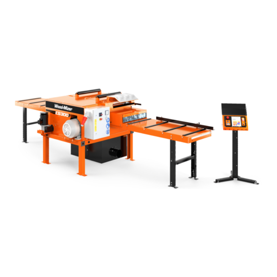
Servicing The Edger Edger Components Edger Components See Figure 1-3. The major components of the EG300 Edger are shown below. Outfeed Table Blade Position Motor Electric Box Control Panel Motor Sawdust Hopper Infeed Table FIG. 1-3 EG300 Servicing The Edger EGdoc022715... - Page 14 Servicing The Edger Edger Components See Figure 1-4. The major components of the EG250 Edger are shown below. Outfeed Table Electric Box with Control Panel Motor Blade Position Dial Infeed Table FIG. 1-4 EG250 EGdoc022715 Servicing The Edger...
-
Page 15: Safety
SAFETY Safety Symbols SECTION 2 SAFETY Safety Symbols The following symbols and signal words call your attention to instructions concerning your personal safety. Be sure to observe and follow these instructions. DANGER! indicates an imminently hazardous situation which, if not avoided, will result in death or serious injury. - Page 16 It is always the owner's responsibility to comply with all applicable federal, state and local laws, rules and regulations regarding the ownership and operation of your Wood-Mizer Edger. All Wood-Mizer owners are encouraged to become thoroughly familiar with these applicable laws and comply with them fully while using the Egder.
- Page 17 SAFETY Keep Egder And Area Around Clean Keep Egder And Area Around Clean DANGER! Maintain a clean and clear path for all necessary movement around the Egder and lumber stacking areas. Failure to do so will result in serious injury. Dispose Of Sawing By-Products Properly IMPORTANT! Always properly dispose of all sawing by-products,...
- Page 18 SAFETY Keep Hands Away Keep Hands Away DANGER! Motor components can become very hot during operation. Avoid contact with any part of a hot motor. Contact with hot motor components can cause serious burns. Therefore, never touch or perform service functions on a hot motor. Allow the motor to cool sufficiently before beginning any service function.
- Page 19 SAFETY Use Proper Maintenance Procedures IMPORTANT! The cutting width system is equipped with a safety switch. When you feed a board into edger, the cutting width setting is blocked. Use Proper Maintenance Procedures DANGER! Make sure all electrical installation, service and/or maintenance work is performed by a qualified electrician and is in accordance with applicable electrical codes.
- Page 20 SAFETY Keep Safety Labels In Good Condition Keep Safety Labels In Good Condition IMPORTANT! Always be sure that all safety decals are clean and readable. Replace all damaged safety decals to prevent personal injury or damage to the equipment. Contact your local distributor, or call your Customer Service Representative to order more decals.
- Page 21 SAFETY Safety Labels Description TABELA 2-1 096319 Always disconnect the power cord before opening the electric box. 099540 CAUTION! Gear train - Keep safe distance! 099540 S12004G Always wear eye protection equipment when operating this machine. S12005G Always wear ear protection equipment when operating this machine.
- Page 22 SAFETY Safety Labels Description TABELA 2-1 501465 Always wear safety boots when operating this machine. 501467 Lubrication point 099504 Visible and/or invisible laser radiation. Avoid eye or skin exposure to direct or scattered radiation. 099504 P85070 CE certified machine 089296 Rotation direction 089296 S20097...
-
Page 23: Operation
OPERATION Pre-Operation Check SECTION 3 OPERATION Pre-Operation Check Prior to operating the Edger; always perform these basic checks: 1. Make sure the Edger is level. Secure the legs to the surface. Cement pads or foundations must be built. Legs must be fastened to the foundation using 16mm anchored bolts. CAUTION! Always be sure the machine is level prior to operating. - Page 24 OPERATION Pre-Operation Check Anti-kickback Lever Tb0044E FIG. 3-1 5. Be sure all guards and covers are in place and secured. DANGER! Make sure all guards and covers are in place and secured before operating or towing the Edger. Failure to do so may result in serious injury.
- Page 25 OPERATION Pre-Operation Check the front or at the rear of the Edger. Emergency Stop Twist to release Tb0054 Tb0045c FIG. 3-2 EG300 E-STOP LOCATION (CE ONLY) EG3002-2 FIG. 3-3 EG300 E-STOP LOCATION (U.S. ONLY)) Operation EGdoc022715...
- Page 26 OPERATION Pre-Operation Check Emergency Stop Twist to release tb0088 FIG. 3-4 EG250 E-STOP LOCATION (CE ONLY) EGdoc022715 Operation...
-
Page 27: Control Overview
OPERATION Control Overview Control Overview Control Panel, EG300 See Figure 3-5. The control panel includes: START-STOP switch, blade distance automatic controller, feed rate knob, automatic controller ON/OFF (CE Only) switch, additional switches for Operation EGdoc022715... - Page 28 OPERATION Control Panel, EG300 setting blades distance and emergency stop button. Real Size (mm) Check real size START TBS 01 Setworks STOP Position Size (mm) SAVE ABCDE AUTO ENTER CAL. REAL SIZE Tb0039C FIG. 3-5 EG300 CONTROL PANEL COMPONENTS (CE ONLY) ENTER EG3004 FIG.
- Page 29 OPERATION Control Panel, EG250 1. Blade Drive To start the blade motor press the START button. To stop the blade motor, press the STOP button. 2. Feed Roller Speed Adjustment The feed roller speed switch controls the speed at which the feed roller moves. Turn the switch right to increase the speed, turn left to reduce the speed.
-
Page 30: Edger Setup3-8
OPERATION Edger Setup 2. Motors START/STOP Button To start the blades and feed motors press the START button. To stop the motors, press the STOP button. 3. Ammeter Indicates current power consumption of all machine motors. 4. Emergency Stop Push the emergency stop button to stop all motors. Turn the emergency stop clockwise to release the stop. - Page 31 OPERATION Edger Setup The machine operator’s (two persons) position is shown below Tb0042C FIG. 3-7 EG300 Tb0042D.cdr TB0042D revA 513516_MANUALS_OPER FIG. 3-8 EG250 Have a qualified electrician install the power supply (according to EN 60204 Standard). The power supply must meet the specifications given in the table below. 3-Phase Volts Fuse Suggested Wire Size...
- Page 32 OPERATION Edger Setup IMPORTANT! When starting the machine for the first time, check that blade rotation direction is as indicated by the arrow located on the blades covers. If the rotation direction is incorrect, invert the phases in the phase inverter located in the power socket (electric box). Setting the phases in the phase inverter correctly will ensure correct rotation directions of all machine motors.
- Page 33 OPERATION Edger Setup Mount the outfeed table using M12x40 bolts, 13 washers and M12 nuts. FIG. 3-10 Mount the outfeed table using the M12x40 bolts, 13 washers, M12 nuts and the supplied special spacers (1 and 1.5mm thick). Place a bar along the inside edge of the blade as shown in the figure # 3-12.
- Page 34 OPERATION Edger Setup are equal. FIG. 3-11 FIG. 3-12 3-12 EGdoc022715 Operation...
-
Page 35: Machine Start
OPERATION Machine Start Machine Start DANGER! Before starting the machine, perform these steps to avoid injury and/or damage to the equipment: Close the blade housing covers and replace any guards removed for service. Check the feed rollers and remove all loose objects such as tools, wood, etc. ... - Page 36 OPERATION Machine Start Real Size (mm) Check real size START TBS 01 Setworks STOP Position Size (mm) SAVE ABCDE AUTO ENTER CAL. REAL SIZE Tb0039C FIG. 3-13 EG300 CONTROL PANEL (CE ONLY) ENTER EG3004 FIG. 3-13 EG300 CONTROL PANEL (U.S. ONLY) 3-14 EGdoc022715 Operation...
- Page 37 OPERATION Machine Start tb0089 FIG. 3-13 EG250 CONTROL PANEL Operation EGdoc022715 3-15...
- Page 38 OPERATION Machine Start See Figure 3-14. The speed at the feed rollers move is adjustable by dial lockated on the control panel, allows the operator to adjust the feed rate from 0 to ca. 25 m / 82 ft per minute. Real Size (mm) Check real size START...
- Page 39 OPERATION Machine Start tb0089 FIG. 3-14 EG250 Turn the switch clockwise to increase the feed rate, counterclockwise to slow the feed rate down. Factors that will determine what feed rate you can use include: Material thickness. Hardness of material to be cut. Some woods that are seasoned or naturally very hard will ...
-
Page 40: Blade Installation
The main shaft’s strength and motor horsepower allows you to use maximally five blades with your Edger. Never use more than five blades! The standard Wood-Mizer Edger is equipped with two blades. The additional three blades in Edger are installed on the provided bushing with spacers. - Page 41 OPERATION Multirip Option (11.22") 285mm 285mm (11.22") FIG. 3-15 NOTE(EG300 only) (CE Only): After installing the additional bushing with blades, you should turn off the Setworks controller because the remaining range of movable blade movement is insufficient for performing the auto-calibration. However, you can still automatically move the movable blade in the remaining range of its movement - using the additional blades distance setting switches located below the Setworks controller ON/OFF switch.
- Page 42 OPERATION Multirip Option Real Size (mm) Check real size START TBS 01 Setworks Setworks STOP Position Size (mm) Controller Switch SAVE ABCDE Additional Blades Distance Setting AUTO ENTER CAL. Buttons REAL SIZE Tb0039C FIG. 3-16EG300 (CE ONLY) ENTER EG3004 FIG. 3-17 EG300 (U.S. ONLY) The table below will help you choose suitable thickness and number of spacers for various numbers of blades and distances between them.
- Page 43 OPERATION Multirip Option Thickness and number of spacers filling the spacing behind the last blade (up to the nut) Thickness and number of spacers behind each blade except the last one G [mm] / inch(") G=26,1 G=10 G=20 Number of spacers 1.028"...
- Page 44 OPERATION Additional Fixed Blade Option - for 3 blades 65 mm (2.56") - for 4 blades 40 mm (1.57") - for 5 blades 25 mm (1") Additional Fixed Blade Option The edger can be equipped with an additional fixed blade (optional equipment). NOTE: It is necessary to readjust the movable blade limit switch after mounting the additional fixed blade (or blades).
-
Page 45: Edging Lumber
OPERATION Edging Lumber Edging Lumber DANGER! Make sure all guards and covers are in place and secured before operating the Edger. Failure to do so may result in serious injury. DANGER! Keep all persons out of the path of moving equipment and boards when operating the Edger or loading boards. - Page 46 OPERATION Edging Lumber See Figure 3-20. The board guide fence allows guide the board parallel. Release the locking bolt to adjust the board guide fence. Board Guide Fence Locking Bolt Laser Guides Tb0068B FIG. 3-20 4. Move the blades as desired. If using a fence as a guide, use the corresponding scale to determine the width of the board after edging.
- Page 47 OPERATION Edging Lumber and/or Edger operation, press the Emergency Stop button located at the front or at the rear of the Edger. 6. Repeat the above procedures for all boards to be edged. 7. Shutdown the machine when done edging. Operation EGdoc022715 3-25...
-
Page 48: Setworks Operation (Eg300 Ce Only)
SETWORKS OPERATION (EG300 ce Only) Edger Controller Panel SECTION 4 SETWORKS OPERATION (EG300 CE ONLY) Edger Controller Panel See Pic. 4-1. Real Size (mm) Real Blades Indicates Check real size Distance that the real saw heads distance should be Set Blades checked Distance TBS 01 Setworks... -
Page 49: Start-Up Settings Of The Controller
SETWORKS OPERATION (EG300 ce Only) Start-up settings of the controller Descriptions of the control panel buttons: A, B, C, D, E - blades width memory buttons. SET ABCDE - Sets the blades width value to each memory button. ABCDE Save - Saves parameters determined by operator. SAVE Blades width manual setting buttons (in/out). - Page 50 SETWORKS OPERATION (EG300 ce Only) Start-up settings of the controller See Pic. 4-2. Real Size (mm) Check real size TBS 01 Setworks Position Size (mm) SAVE ABCDE AUTO ENTER CAL. REAL SIZE PIC. 4-2 Press to save the entered divider value. ...
- Page 51 SETWORKS OPERATION (EG300 ce Only) Start-up settings of the controller See Pic. 4-3. Real Size (mm) Check real size TBS 01 Setworks Position Size (mm) SAVE ABCDE AUTO ENTER CAL. REAL SIZE PIC. 4-3 Press again, the controller successively performs some movements of the blades. AUTO ...
-
Page 52: Operation, Memory Buttons (A, B, C, D, E)
SETWORKS OPERATION (EG300 ce Only) Operation, Memory Buttons (A, B, C, D, E) on the scale. If not, for alignment instructions. See Section 6.7 Enter the distance between the blades without any pauses. Confirm by pressing ENTER Operation, Memory Buttons (A, B, C, D, E) After switching-on, the TBS-01 inscription appears on the display, and the setworks is ready for operation within a few seconds or after is pressed. - Page 53 SETWORKS OPERATION (EG300 ce Only) Operation, Memory Buttons (A, B, C, D, E) See Pic. 4-4. Real Size (mm) Check real size TBS 01 Setworks Position Size (mm) SAVE ABCDE AUTO ENTER CAL. REAL SIZE PIC. 4-4 To use the stored value, press the required memory button and confirm by pressing .
-
Page 54: Setworks Operation (Eg300 U.s. Only)
Setworks Operation (EG300 U.S. Only) Setworks (Optional - U.S. Version) SECTION 5 SETWORKS OPERATION (EG300 U.S. ONLY) Setworks (Optional - U.S. Version) The Setworks option allows you to program eight positions for the blades and adjust to those positions by pushing a single button. For Setworks to be operational, the power to the machine must be on and the green power indicator on the operator control illuminated. - Page 55 Setworks Operation (EG300 U.S. Only) Setworks (Optional - U.S. Version) See Figure 5-3. After the Setworks display scrolls through the start-up screens, the Main screen will be displayed. Depending on how the control is programmed, the Main screen will display in one of three unit options: Imperial Fractions, Imperial Decimals or Metric.
- Page 56 Setworks Operation (EG300 U.S. Only) Setworks (Optional - U.S. Version) 5.1.4 Select Unit Of Measure See Figure 5-5. Push the left arrow labeled ‘Cfg.’ to enter the Configuration menu. Use the F1, F2 or F3 buttons to select the unit of measure you wish to use. The units currently selected will be labeled ‘ON’.
- Page 57 Setworks Operation (EG300 U.S. Only) Setworks (Optional - U.S. Version) 5.1.6 Calibrate Blades Position After the Setworks option is installed or if inaccurate position of the blades is observed, calibration of the Setworks control with the saw head position may be required. Adjust the blade positions so the blades are an easy-to-measure distance from each other.
- Page 58 Setworks Operation (EG300 U.S. Only) Setworks (Optional - U.S. Version) 5.1.8 Adjust Preset Values See Figure 5-9. To enter different values for each preset, push the right arrow button labeled ‘Page 2” from the Main screen. Push the right arrow again to enter the presets Setup menu. Push the left arrow ‘Back’...
- Page 59 Setworks Operation (EG300 U.S. Only) Setworks (Optional - U.S. Version) See Figure 5-10. In the Setup menu, select the corresponding ‘F’ button for the value you wish to set. Push the right arrow ‘Next’ button to scroll to Presets 5-8. Once you select a Preset to change, the Position Set menu will appear.
-
Page 60: Maintenance & Alignment
Maintenance & Alignment Changing the Blades SECTION 6 MAINTENANCE & ALIGNMENT Changing the Blades 1. Replace the blades as necessary. Dull blades will cause the motor to work harder and will result in decreased cut quality and accuracy. Blade life will vary depending on maintenance of machine, operator, species of wood being sawn, and condition of wood being sawn. - Page 61 Maintenance & Alignment Changing the Blades See Figure 6-1. Mounting Nuts(3) Plate Assembly Cone Retaining Bolt Cone/Bearing tb0055a Assembly Blade Shaft Bearing Guard Bearing Puller FIG. 6-1 5. Next, remove the blades from the shaft. To do this, remove the fixed blade locking nut using the provided spanner wrenches and next remove the fixed blade.
- Page 62 Maintenance & Alignment Changing the Blades See Figure 6-2. Spanner Movable Wrenches Blade Arbor Fixed Blade Blade Locking FIG. 6-2 7. Apply an anti-seize lubricant to the face of the arbor and to the face and threads of the blade locking nut.
-
Page 63: Tensioning The Belts
Maintenance & Alignment Tensioning the Belts Tensioning the Belts DANGER! Always shut off the motor and allow all moving parts to come to a complete stop before removing any guards or covers. Failure to do so will result in serious injury. Before tensioning the belts, make sure the motor is shut off completely and the main switch is in "0"... -
Page 64: Tensioning The Chains
Maintenance & Alignment Tensioning the Chains Drive Belts Mounting Bolts Adjustment Bolts FIG. 6-3 Tensioning the Chains Board Feed Drive Chains Check the board feed drive chains for tension every 40 hours of operation and tension as necessary. See Figure 6-4. To tension the drive chains, unbolt and open the gearbox housing cover. Loosen the chain tensioner socket bolt. - Page 65 Maintenance & Alignment Tensioning the Chains Retighten the gearbox mounting bolts and close and secure the gearbox housing cover. TB0050B Tensioner Socket Bolt FIG. 6-4 Blade & Laser Positioning Chains Check the blade and laser positioning chains for tension every 100 hours of operation and tension as necessary.
- Page 66 Maintenance & Alignment Tensioning the Chains Adjustment Bolts (2) Locking Bolts (4) FIG. 6-5 EG300 Adjustment Bolts (1) Locking Bolts (3) Tb0080b.cdr TB0080B revA 513516_MANUALS_OPER FIG. 6-5 EG250 EGdoc022715 Maintenance & Alignment...
-
Page 67: Checking The Rollers
Maintenance & Alignment Checking the Rollers See Figure 6-6. To tension the laser positioning chain (EG300 only), unbolt and remove the blade housing cover. Loosen the sprocket axle mounting bolt. Using adjustment bolt, tension the chain. After that, tighten the sprocket axle mounting bolt. Sprocket Axle Mounting Bolt Adjustment Bolt... -
Page 68: Anti-Kickback Fingers Maintenance
Maintenance & Alignment Anti-Kickback Fingers Maintenance 4. Lubricate the hold-down roller bearings every 200 hours of operation with a high-quality lithium-based grease such as Shell Alvania No. 3. 5. Apply anti-seize lubricant to the surfaces and threads of the blade arbors and locking nuts every blade change (See Section 4.1). - Page 69 Maintenance & Alignment Alignment 3. Place a 60mm wide bar along the outside edge of the blade and so that the bar is aligned with the 0 mark on the scale and the bar meets the fence. See Figure 6-7. 4.
- Page 70 Maintenance & Alignment Alignment Controller (See Section 4.2) (EG300 only). Correct the scale indicator position if necessary (EG300 only). See Figure 6-8. Laser Beam Scale Indicator Laser Beam FIG. 6-8 6-11 EGdoc022715 Maintenance & Alignment...
-
Page 71: Blade Sharpening
Maintenance & Alignment Blade Sharpening Blade Sharpening The blade teeth should be sharpened as soon as their dullness, measured as shown in the figure on the right, is .10 -.20 mm (0.0039 - 0.0078"). Use diamond grinding wheels for sharpening the blades. Apply intensive cooling during sharpening to prevent overheating and structural changes in the cemented carbide tips. -
Page 72: Using The Blades
Maintenance & Alignment Using the Blades Using the Blades The surfaces of spacers should be clean and flat against one another. The blade should not rotate on the shaft during sharpening as it will lead to its damage. Do not set teeth with cemented carbide tips! Do not make any modifications to the blade teeth! Do not operate the machine if any of the blades is dull. -
Page 73: Eg300 Safety Devices Inspection (Ce Version Only)
Maintenance & Alignment EG300 Safety Devices Inspection (CE version only) 6.10 EG300 Safety Devices Inspection (CE version only) Cover #2 Cover # E-STOP on Housing Sawdust Control Box Hopper Tb0044E E-STOP Anti-Kickback Lever FIG. 6-9 The following safety devices on the EG300 Edger must be inspected before every shift: E-STOP button circuit - control box ... - Page 74 Maintenance & Alignment EG300 Safety Devices Inspection (CE version only) Push the E-STOP button located on the control box. The motor should stop. It should not be possible to restart the motor until the E-STOP is released. 2. Housing E-STOP Button Circuit Inspection Start the main motor;...
- Page 75 Maintenance & Alignment EG300 Safety Devices Inspection (CE version only) Start the main motor; Open the cover #2; The main motor should stop; Try to start the motor using the START button. It should not be possible to start the motor. ...
- Page 76 Maintenance & Alignment EG300 Safety Devices Inspection (CE version only) Repeat the above step using the LEFT arrow on the Setworks control panel. 6. Maximum Blades Distance Safety Switch Inspection Press and hold the RIGHT arrow on the control box until the blades distance setting is stopped; ...
- Page 77 Maintenance & Alignment EG300 Safety Devices Inspection (CE version only) Push down the lever shown below; Tb0079 FIG. 6-13 Check again if it is possible to set the blades distance using the appropriate button on the control box and on the Setworks. Maintenance &...
- Page 78 Maintenance & Alignment EG300 Safety Devices Inspection (CE version only) 8. Safety Switch Circuit Inspection - Anti-kickback Fingers (Two Persons) FIG. 6-14 Start the main motor; 6-19 EGdoc022715 Maintenance & Alignment...
- Page 79 Maintenance & Alignment EG300 Safety Devices Inspection (CE version only) Push the anti-kickback lever (shown below) down to raise the anti-kickback fingers; FIG. 6-15 The main motor should stop; With the anti-kickback fingers raised, try to start the motor using the START button. It should ...
- Page 80 Maintenance & Alignment EG300 Safety Devices Inspection (CE version only) Lower the anti-kickback fingers to their working position. FIG. 6-16 9. Motor Brake and its Circuit Inspection Start the motor. Stop the motor by pushing the STOP button. Measure the braking time. ...
-
Page 81: Eg250 Safety Devices Inspection (Ce Version Only)
Maintenance & Alignment EG250 Safety Devices Inspection (CE version only) 6.11 EG250 Safety Devices Inspection (CE version only) Cover # Control Box E-STOP E-STOP on Housing Sawdust Hopper Anti-Kickback Lever FIG. 6-17 The following safety devices on the EG300 Edger must be inspected before every shift: E-STOP button circuit - control box ... - Page 82 Maintenance & Alignment EG250 Safety Devices Inspection (CE version only) Push the E-STOP button located on the edger housing. The motor should stop. It should not be possible to restart the motor until the E-STOP is released. 3. Cover Safety Switch Circuit Inspection Start the main motor;...
- Page 83 Maintenance & Alignment EG250 Safety Devices Inspection (CE version only) Close the sawdust hopper cover; The motor should remain turned off. Maintenance & Alignment EGdoc022715 6-24...
- Page 84 Maintenance & Alignment EG250 Safety Devices Inspection (CE version only) 8. Safety Switch Circuit Inspection - Anti-kickback Fingers (Two Persons) FIG. 6-19 Start the main motor; 6-25 EGdoc022715 Maintenance & Alignment...
- Page 85 Maintenance & Alignment EG250 Safety Devices Inspection (CE version only) Push the anti-kickback lever (shown below) down to raise the anti-kickback fingers; FIG. 6-20 The main motor should stop; With the anti-kickback fingers raised, try to start the motor using the START button. It should ...
- Page 86 Maintenance & Alignment EG250 Safety Devices Inspection (CE version only) Lower the anti-kickback fingers to their working position. FIG. 6-21 9. Motor Brake and its Circuit Inspection Start the motor. Stop the motor by pushing the STOP button. Measure the braking time. ...
-
Page 87: Specifications
SPECIFICATIONS Overall Dimensions SECTION 7 SPECIFICATIONS Overall Dimensions See Figure 7-1. The major dimensions of the EG300 Edger are shown below (dimensions are in millimeters and inches). (70.79 ) " (50.79 ) " (184.68 ) " Tb0037B (64.49 ) " FIG. - Page 88 SPECIFICATIONS Overall Dimensions See Figure 7-3. The major dimensions of the EG250 Edger are shown below (dimensions are in millimeters and inches). FIG. 7-4 EGdoc022715 Specifications...
-
Page 89: Multirip Edger Specifications
SPECIFICATIONS Multirip Edger Specifications Multirip Edger Specifications See Table 7-2 The power option specifications of the Wood-Mizer Edger is listed below Motor Specifications Motor Specifications Motor Specifications (CE and U.S.) (CE and U.S.) Motor Type E20 Electric Motor E25 Electric Motor... - Page 90 SPECIFICATIONS Multirip Edger Specifications See Table 7-4 Other specifications of the Edger are listed below. Number of Blades 2 - 5 ") Blade Diameter 350 mm (13.78 Feed Speed 0 - 25m(82 ft)/min Minimum Board Length ") 700 mm (27.56 ") Minimum Board Thickness 10 mm (0.394...
-
Page 91: Dust Extractor Specifications
SPECIFICATIONS Dust Extractor Specifications Dust Extractor Specifications See Table 7-5 Specifications of the dust extractors used on the Edger are listed below. Airflow 1200 m 3937 ft Inlet diameter ") 150 mm (5.905 Motor power 1,5 kW Number of sacks 2 pcs Sack capacity 0.25 m... -
Page 92: Electrical Information (Ce Only)
Electrical Information (ce only) SECTION 8 ELECTRICAL INFORMATION (CE ONLY) EGdoc022715 Electrical Information... -
Page 93: Electrical Diagram Eg300Eb_S (230V 50/60 Hz)
Electrical Information (ce only) Electrical Diagram EG300EB_S (230V 50/60 Hz) Electrical Diagram EG300EB_S (230V 50/60 Hz) FIG. 8-1 Electrical Information EGdoc022715... -
Page 94: Electrical Diagram Eg300Eb (230V 50/60 Hz)
Electrical Information (ce only) Electrical Diagram EG300EB (230V 50/60 Hz) Electrical Diagram EG300EB (230V 50/60 Hz) FIG. 8-2 EGdoc022715 Electrical Information... -
Page 95: Electrical Diagram Eg300Ec (460V 50/60 Hz)
Electrical Information (ce only) Electrical Diagram EG300EC (460V 50/60 Hz) Electrical Diagram EG300EC (460V 50/60 Hz) FIG. 8-3 Electrical Information EGdoc022715... -
Page 96: Electrical Diagram Eg300Eh (400V 50/60 Hz)
Electrical Information (ce only) Electrical Diagram EG300EH (400V 50/60 Hz) Electrical Diagram EG300EH (400V 50/60 Hz) FIG. 8-4 EGdoc022715 Electrical Information... -
Page 97: Electrical Diagram Eg300Eh_S (400V 50/60 Hz)
Electrical Information (ce only) Electrical Diagram EG300EH_S (400V 50/60 Hz) Electrical Diagram EG300EH_S (400V 50/60 Hz) FIG. 8-5 Electrical Information EGdoc022715... -
Page 98: Electrical Component List, Eg300Eb_S (230V 50/60 Hz)
Electrical Information (ce only) Electrical Component List, EG300EB_S (230V 50/60 Hz) Electrical Component List, EG300EB_S (230V 50/60 Hz) See Table 8-1 SYMBOL DESCRIPTION WOOD-MIZER MANUFACTURER PART NO. SWITCH, ABB OT63F3 503466 Switch, GV3 M80 503549 SCHNEIDER ELECTRIC CIRCUIT BREAKER, C60N 3P C10... -
Page 99: Electrical Component List, Eg300Ec (460V 50/60 Hz)
Electrical Information (ce only) Electrical Component List, EG300EC (460V 50/60 Hz) Electrical Component List, EG300EC (460V 50/60 Hz) See Table 8-2 Symbol Description Wood-Mizer Manufacturer Part No. Switch, ABB OT40F3 502312 Switch, GV3 P40 SCHNEIDER 090436 SCHNEIDER ELECTRIC Circuit Breaker, C60N 3P C6... -
Page 100: Electrical Component List, Eg300Eh_S (400V 50/60 Hz)
Electrical Information (ce only) Electrical Component List, EG300EH_S (400V 50/60 Hz) Electrical Component List, EG300EH_S (400V 50/60 Hz) See Table 8-3 Symbol Description Wood-Mizer Manufacturer Part No. Switch, ABB OT40F3 502312 Switch, GV3 P40 SCHNEIDER 090436 SCHNEIDER ELECTRIC Circuit Breaker, C60N 3P C6... -
Page 101: Electrical Diagram, Eg250 (400V 50/60 Hz) - African Version
Electrical Information (ce only) Electrical Diagram, EG250 (400V 50/60 Hz) - African Version Electrical Diagram, EG250 (400V 50/60 Hz) - African Version FIG. 8-6 Electrical Information EGdoc022715 8-10... -
Page 102: Electrical Diagram, Eg250Ec (400V 50/60 Hz) - Russian Version
Electrical Information (ce only) Electrical Diagram, EG250EC (400V 50/60 Hz) - Russian Version 8.10 Electrical Diagram, EG250EC (400V 50/60 Hz) - Russian Version FIG. 8-7 8-11 EGdoc022715 Electrical Information... -
Page 103: Electrical Diagram, Eg250S (400V 50/60 Hz) - Ce Version
Electrical Information (ce only) Electrical Diagram, EG250S (400V 50/60 Hz) - CE Version 8.11 Electrical Diagram, EG250S (400V 50/60 Hz) - CE Version FIG. 8-8 Electrical Information EGdoc022715 8-12... -
Page 104: Electrical Component List, Eg250 (400V 50/60 Hz) African Version8-13
Electrical Information (ce only) Electrical Component List, EG250 (400V 50/60 Hz) African Version 8.12 Electrical Component List, EG250 (400V 50/60 Hz) African Version See Table 8-4 Symbol Description Wood-Mizer Manufacturer Part No. Switch, ABB OT40F3 Disconnect 502312 F1 (E20) Breaker, GZ1M32 Motor Circuit... -
Page 105: Electrical Component List, Eg250Ec (400V 50/60 Hz) - Russian Version8-14
Electrical Information (ce only) Electrical Component List, EG250EC (400V 50/60 Hz) - Russian Version 8.13 Electrical Component List, EG250EC (400V 50/60 Hz) - Russian Version See Table 8-5 Symbol Description Wood-Mizer Manufacturer Part No. Switch, ABB OT40F3 Disconnect 502312 F1 (E20) -
Page 106: Electrical Component List, Eg250S (400V 50/60 Hz) - Ce Version
Electrical Information (ce only) Electrical Component List, EG250S (400V 50/60 Hz) - CE Version 8.14 Electrical Component List, EG250S (400V 50/60 Hz) - CE Version See Table 8-6 Symbol Description Wood-Mizer Manufacturer Part No. Switch, ABB OT40F3 Disconnect 502312 F1 (E20) -
Page 107: Electrical Information (U.s. Only)
Electrical Information (ce only) Electrical Component List, EG250S (400V 50/60 Hz) - CE Version Electrical Information EGdoc022715 8-16... -
Page 108: Electrical Diagram, Eg300Ec25U (U.s. Only)
Electrical Information (U.S. Only) Electrical Diagram, EG300EC25U (U.S. Only) SECTION 9 ELECTRICAL INFORMATION (U.S. ONLY) Electrical Diagram, EG300EC25U (U.S. Only) 480 VAC 1/L1 2/T1 60 A 3/L2 4/T2 5/L3 6/T3 2.216 1/L1 2/T1 3/L2 4/T2 5/L3 6/T3 2.213 2.214 1/L1 2/T1 1/L1 2/T1... - Page 109 Electrical Information (U.S. Only) Electrical Diagram, EG300EC25U (U.S. Only) 100-200/200-500VAC 24 VDC 1.110 1.109 Class CC 24V(-) / 5.503 24V(+) / 5.502 11 14 55(2) 55A(1) Laser Option Laser Laser 1.110 5.507 .213 .214 .216 1.107 57(5) 1.107 1.108 1.107 .214 1.105 1.105...
- Page 110 Electrical Information (U.S. Only) Electrical Diagram, EG300EC25U (U.S. Only) 1.111 Feed Rollers 2.214 65(6) 66(7) 67(8) +10V Reference 2 of 2 Project Description Page Description: EG300 Edger w/Setworks Type: Schematic multi-line Modification Date Name Date Name Created 8/8/2013 nehmi Edited 8180 W 10th St 11/25/2013 Indianapolis, IN 46214 USA...
- Page 111 Electrical Information (U.S. Only) Electrical Diagram, EG300EC25U (U.S. Only) 1.116 Blade In/Out RLY_COM_0 5.509 68(9) Board Present 70(10) Blade IN Travel Limit (IN) 72(11) Blade OUT Travel Limit (OUT) BLADE_IN 5.510 BLADE_OUT 5.509 74(12) SPEED_SEL 5.510 +10V Reference 2 of 2 Project Description Page Description: EG300 Edger w/Setworks...
- Page 112 Electrical Information (U.S. Only) Electrical Diagram, EG300EC25U (U.S. Only) PLC1 .508 .508 Power Supply TWDLCDA16RDF 55B(13) 24V(+) 2.205 24VDC(+) 53B(14) 24V(-) 2.204 24VDC(-) RS485 2.211 PLC1 PLC1 .502 .502 Digital Inputs Digital Outputs RLY_COM_0 DC_IN_COM RLY_COM_0 / 4.404 76(16) 76(16) BLADE_OUT QO.0 IO.0...
-
Page 113: Electrical Component List, , Eg300Ec25U (U.s. Only)
Electrical Information (U.S. Only) Electrical Component List, , EG300EC25U (U.S. Only) Electrical Component List, , EG300EC25U (U.S. Only) Symbol Manufacturer Manufacturer Wood-Mizer Description Part No. Part No. LC1D32BD 052465 Contactor TeSys LC1-D - 3P - AC-3 440V 32A LC1D32BD 052465... -
Page 114: Replacement Parts
Kolo, Nagórna 114 St, Poland at +48-63-2626000. From the continental U.S., call our U.S. Headquarter 8180 West 10th St.Indianapolis, IN 46214, toll-free at 1-800-525-8100. Have your customer number, VIN, and part numbers ready when you call. From other international locations, contact the Wood-Mizer distributor in your area for parts. Office Hours: Country... -
Page 115: Main Shaft Assembly
REPLACEMENT PARTS Main Shaft Assembly 10.2 Main Shaft Assembly REF. DESCRIPTION ( Indicates Parts Available In Assemblies Only ) PART # MAIN SHAFT, EDGER EG300 COMPLETE 503887 BLADE, PI-510 350x3.9/2.6/76 Z-24+4GM 089144 BEARING, NSK UKP211D1 101109 SLEEVE, H2311H ADAPTER 503075 COVER, SIDE W/BEARING COMPLETE 503143 BEARING, NSK UKP211D1... - Page 116 REPLACEMENT PARTS Main Shaft Assembly ARBOR, FIXED BLADE ZINC 089091-1 NUT, BLADE RETAINER PTD 089092-1 ARBOR, MOVING BLADE ZINC-PLATED 089093-1 WRAP, EDGER ZINC-PLATED 089116-1 BEARING, 6014 2RS1 CX BALL 089164 RING, Z70 OUTSIDE RETAINING 089165 RING, W110 INSIDE RETAINING 089166 BLOCK, BLADE SLIDE 500527-1 SHAFT, BLADE CHROME...
-
Page 117: Spacer Mounting Kit (Optional)
REPLACEMENT PARTS Spacer Mounting Kit (Optional) 10.3 Spacer Mounting Kit (Optional) Tb0069B REF. DESCRIPTION ( Indicates Parts Available In Assemblies Only ) PART # QTY. MOUNTING KIT FOR 5 BLADES W/LONG BUSHING 093328 COLLAR, LOCKING (EDGER) 089116 RING, SPACER 090967-1 SPACER 090968-1 SPACER, G=5 THICK... -
Page 118: Infeed Rollers Assembly
REPLACEMENT PARTS Infeed Rollers Assembly 10.4 Infeed Rollers Assembly Tb0058E REF. DESCRIPTION ( Indicates Parts Available In Assemblies Only ) PART # QTY. INFEED ROLLER DRIVE ASSEMBLY, COMPLETE 503145 SPROCKET, Z14 5/8"x3/8" W/BEARING 088867 MOTOREDUCER, MR-80/64/1.1-1400/K3/V6 098663 ROLLER, INFEED COMPLETE 503144 BEARING, UCFL 205 CX W/HOUSING 089124... - Page 119 REPLACEMENT PARTS Infeed Rollers Assembly CHAIN, 10B-1-141 503180 LINK, 10B-1Pz MASTER 088671 TENSIONER, TEKS 5, CHAIN COMPLETE 503884 TENSIONER, TEKS5 5/8x3/8-12S (T31678+T29422). CHAIN 503883 BOLT, M6x16 -8.8- SOCKET HEAD ZINC F81001-21 NUT, M6-8-B-HEX NYLON ZINC LOCK F81031-2 WASHER, 6,4 FLAT ZINC F81053-1 BUSHING, 45x16.5x45, SPACER ZINC 503893-1...
-
Page 120: Hold-Down Roller & Anti-Kickback Assembly (Eg300)
REPLACEMENT PARTS Hold-Down Roller & Anti-Kickback Assembly (EG300) 10.5 Hold-Down Roller & Anti-Kickback Assembly (EG300) TB0052G REF. DESCRIPTION ( Indicates Parts Available In Assemblies Only ) PART # QTY. HOLD-DOWN ROLLER, COMPLETE 503150 ROLLER, REAR HOLD-DOWN COMPLETE (2) 507536 BEARING, UCFL 205 CX W/HOUSING 089124 TENSIONER, ZINC-PLATED 089153-1... - Page 121 REPLACEMENT PARTS Hold-Down Roller & Anti-Kickback Assembly (EG300) BOLT, M16x40-8.8 HEX HEAD FULL THREAD ZINC F81006-13 BOLT, M16X30 8.8 HEX HEAD FULL THREAD ZINC F81006-36 NUT, M10-8-B HEX NYLON ZINC LOCK F81033-1 NUT, M16-8 HEX NYLON ZINC LOCK F81036-2 WASHER, 10.5 FLAT ZINC F81055-1 WASHER, 10.5 SPECIAL FLAT ZINC F81055-6...
-
Page 122: Anti-Kickback Fingers (Eg250)
REPLACEMENT PARTS Anti-Kickback Fingers (EG250) 10.6 Anti-Kickback Fingers (EG250) REF. DESCRIPTION ( Indicates Parts Available In Assemblies Only ) PART # QTY. ANTIKICKBACK ASSEMBLY 513520 SHAFT, ANTI-KICKBACK FINGER ZINC-PLATED 503159-1 BEARING, UCFL 204 (CX). 500060 HANDLE, ANTI-KICKBACK FINGER LIFT 503161-1 PLATE, ANTI-KICKBACK LINK 503162-1 ROD, ANTI-KICKBACK FINGER SUPPORT ZINC-PL. -
Page 123: Blade Setting Assembly
REPLACEMENT PARTS Blade Setting Assembly 10.7 Blade Setting Assembly TB0064B REF. DESCRIPTION ( Indicates Parts Availabe In Assemblies Only ) PART # QTY. BLADE AND LASER SETTING DRIVE ASSEMBLY, COMPLETE 503903 BRACKET, MAGNETIC STRIP 101025-1 STRIP, I=450mm MAGNETIC 101410-1 MOVING BLADE SLIDE SHAFT, COMPLETE 503902 BEARING, COMPLETE 089134... - Page 124 REPLACEMENT PARTS Blade Setting Assembly WASHER, 8,2 SPLIT LOCK ZINC F81054-4 WASHER, 10,5 FLAT ZINC F81055-1 WASHER, 10,2 SPLIT LOCK ZINC F81055-2 WASHER, 791 M10/10.5 RIBBED LOCK F81055-7 WASHER, Z12,2 SPLIT LOCK ZINC F81056-2 MOTOREDUCER, BLADE DISTANCE SETTING DRIVE, COMPLETE 503908 MOTOREDUCER, MR-50/78/0.18-900 K3/B8 101024...
-
Page 125: Laser Guide Assembly (Eg300)
REPLACEMENT PARTS Laser Guide Assembly (EG300) 10.8 Laser Guide Assembly (EG300) tb0067d REF. DESCRIPTION ( Indicates Parts Available In Assemblies Only) PART # QTY. LASER DISTANCE SETTING DRIVE SHAFT 503921 KEY, A 6x6x18 PARALLEL 089404 BEARING, UCP 204 CX 500059 SHAFT, LASER DISTANCE SETTING DRIVE, ZINC-PLATED 503920-1 SPROCKET, Z=13, 10B W/BUSHING S203K COMPLETE... - Page 126 REPLACEMENT PARTS Laser Guide Assembly (EG300) LASER MOUNT AND GUIDE ASSEMBLY 503925 SEAL WIRE, GH6 RUBBER 085338 SCALE, EDGER INCH 101006 SCALE, EDGER METRIC 101007 POINTER, BLADE SCALE 500068-1 GUIDE, CHAIN SR20012018 (EDGER) 500621 BRACKET, AN20012K (complete) MOUNTING 500622 GUARD, EDGER LASER 500743-1 LASER GUIDE, COMPLETE 503916...
- Page 127 REPLACEMENT PARTS Laser Guide Assembly (EG300) BRACKET, MOVABLE LASER PTD 505472-1 SCREW, M5x16-8.8-HEX SOCKET HEAD CAP ZINC F81000-25 BOLT, M6x20-8.8-HEX HEAD FULL THREAD ZINC F81001-2 BOLT, M6x16-8.8-HEX HEAD FULL THREAD ZINC F81001-32 NUT, M5-8-Fe/Zn5 DIN 985 F81030-2 WASHER, 5,3 FLAT ZINC F81052-1 WASHER, 6,4 FLAT ZINC F81053-1...
-
Page 128: Motor Assembly
REPLACEMENT PARTS Motor Assembly 10.9 Motor Assembly TB0060D REF. DESCRIPTION ( Indicates Parts Available In Assemblies Only) PART # QTY. EDGER MOTOR ASSEMBLY, E20 COMPLETE 503183 EDGER MOTOR ASSEMBLY, E25 COMPLETE 503189 MOTOR, 1LA7166-2AA60-Z G26+C01 (E25) 087397 MOTOR ELECTR.15KW WITH BRAKE SG160M2B (E20) 087396 V-BELT, B39 1040 Lp, EDGER 101130... - Page 129 REPLACEMENT PARTS Motor Assembly WASHER, 13 FLAT ZINC F81056-1 WASHER, Z12,2 SPLIT LOCK ZINC F81056-2 HOLD-DOWN ROLLER SAFETY SWITCH, COMPLETE 505860 GLAND, SKINTOP ST PG 13,5 GREY CABLE 086524 SWITCH, GLCB01C SAFETY 100910 CAM, SAFETY SWITCH 500073 BRACKET, SAFETY SWITCH PTD 500140-1 BOLT, M5x16-5.8-HEX HEAD FULL THREAD ZINC F81000-51...
-
Page 130: Control Box (Eg300 Ce Only)
REPLACEMENT PARTS Control Box (EG300 CE ONLY) 10.10Control Box (EG300 CE ONLY) Tb0061c REF. DESCRIPTION ( Indicates Parts Available In Assemblies Only ) PART # QTY. EG300 EDGER CONTROL BOX - COMPLETE 504374 KNOB, 1/4"ID FLUTED ROUND PLASTIC 033478 SWITCH, XB4 BS542 EMERGENCY STOP 086556 WASHER, ZBY9330 EMERGENCY STOP SWITCH 086561... - Page 131 REPLACEMENT PARTS Control Box (EG300 CE ONLY) LINK, M22-A 100905 DECAL, EDGER 1 CONTROL BOX 500035 DECAL, EDGER 2 CONTROL BOX 500035-1 STAND, LT20B CONTROL BOX 501651-1 CONTROLLER, TBS01 503467 CONTROL BOX, TVS 503536-1 PANEL, EG300 CONTROL BOX 504375-1 POTENTIOMETER, 1k E20519 BOLT, #10-24 x 1/2 PH PAN HEAD TYPE 23 F05015-17...
-
Page 132: Electric Box (Eg250)
REPLACEMENT PARTS Electric Box (EG250) 10.11 Electric Box (EG250) REF. DESCRIPTION ( Indicates Parts Available In Assemblies Only ) PART # QTY. COVER, EG250 EDGER FRONT - COMPLETE 513581 PLATE, FRONT EDGER COVER 505488-1 WASHER, 8.4 FLAT ZINC F81054-1 BOLT, M8X20 8.8 HEX HEAD FULL THREAD ZINC F81002-4 NUT, M8 8 HEX NYLON ZINC LOCK F81032-2... - Page 133 REPLACEMENT PARTS Table (EG300) 10.12Table (EG300) REF. DESCRIPTION ( Indicates Parts Available In Assemblies Only ) PART # QTY. TABLE, EDGER COMPLETE 101400 GUARD, BOARD 099299-1 ROLLER, 63.5/20x590 (EDGER) 501090-1 TOP, TABLE 500078-1 BOLT, M8x20-5.8-HEX HEAD FULL THREAD ZINC F81002-1 BOLT, M10x25-8.8-HEX HEAD FULL THREAD ZINC F81003-11 NUT, M8-8-B-HEX ZINC...
- Page 134 REPLACEMENT PARTS Table (EG300) BOLT, M10x25-8.8-HEX HEAD FULL THREAD ZINC F81003-11 BOLT, M10x70-8.8-HEX HEAD FULL THREAD ZINC F81003-20 NUT, M10-8-B-HEX ZINC F81033-3 WASHER, 10,5 FLAT ZINC F81055-1 BOARD ENTER COVER 500143 PLATE, 1 PLASTIC 089380 PLATE, 2 PLASTIC 089381 BAR, PLASTIC PLATE MOUNTING 500142-1 BOLT, M6x30 5.8 HEX HEAD FULL THREAD ZINC F81001-13...
- Page 135 REPLACEMENT PARTS Table (Option for EG250 Edgers) 10.13Table (Option for EG250 Edgers) REF. DESCRIPTION ( Indicates Parts Available In Assemblies Only ) PART # QTY. TABLE, EDGER COMPLETE (W/O GUARDS) 513517 TOP, IND EDGER TABLE 512488-1 ROLLER, 63.5/20X590 501090-1 WASHER,10.5 FLAT ZINC F81055-1 BOLT, M10X25 8.8 HEX HEAD FULL THREAD ZINC F81003-11...
-
Page 136: Board Guide Fence
REPLACEMENT PARTS Board Guide Fence 10.14Board Guide Fence Tb0059 REF. DESCRIPTION ( Indicates Parts Available In Assemblies Only) PART # QTY. COMPLETE BOARD GUIDE FENCE 101100 FENCE, BOARD GUIDE 101020 BUSHING, XFM-1214-12 FLANGED 088934 PIN, DETENT 090197 FENCE, GUIDE 101097-1 BAR, GUIDE FENCE ARM 101098-1 PIN, GUIDE FENCE ARM ZINC-PLATED... -
Page 137: Covers
REPLACEMENT PARTS Covers 10.15Covers 34 35 Tb0056D REF. DESCRIPTION ( Indicates Parts Available In Assemblies Only ) PART # QTY. COVER, UPPER LEFT HINGED - COMPLETE 505484 HINGE, COMPLETE 038136-1 GLAND, SKINTOP ST PG 13,5 GREY CABLE 086524 SWITCH, GSCA 01S1 SAFETY 088407 CAP, BUMPER RUNNER No 646 089083... - Page 138 REPLACEMENT PARTS Covers SCREW, M5x45 DIN912 A2-70 HEX SOCKET HEAD F81000-24 BOLT, M5x16-5.8-HEX HEAD FULL THREAD ZINC F81000-51 BOLT, M8x20-5.8-HEX HEAD FULL THREAD ZINC F81002-1 BOLT, M8x20-8.8 MUSHROOM HEAD SQUARE NECK ZINC F81002-11 BOLT, M8x20-8.8-B-HEX HEAD FULL THREAD ZINC F81002-4 BOLT, M8x30-8.8-B-HEX HEAD FULL THREAD ZINC F81002-7 BOLT, M10x25-8.8-HEX HEAD FULL THREAD ZINC...
-
Page 139: Eg250 Edger Top Cover
REPLACEMENT PARTS EG250 Edger Top Cover 10.16EG250 Edger Top Cover REF. DESCRIPTION ( Indicates Parts Available In Assemblies Only ) PART # QTY. COVER, LEFT TOP HINGED - COMPLETE 513518 COVER, TOP HINGED 505486-1 HINGE, COMPLETE 038136-1 BRACKET, SAFETY SWITCH CAM 089225-1 HANDLE, 4"... -
Page 140: Manual Blade Setting Assembly (Eg250)
REPLACEMENT PARTS Manual Blade Setting Assembly (EG250) 10.17Manual Blade Setting Assembly (EG250) REF. DESCRIPTION ( Indicates Parts Available In Assemblies Only ) PART # QTY. DRIVE ASSEMBLY, MANUAL BLADE SETTING 513519 SHAFT, MOVING BLADE SLIDE - COMPLETE 513522 SHAFT, BLADE SLIDE BRACKET 101417-1 BRACKET, BLADE SLIDE 101009-1... - Page 141 REPLACEMENT PARTS Manual Blade Setting Assembly (EG250) REF. DESCRIPTION ( Indicates Parts Available In Assemblies Only ) PART # QTY. WASHER, Z12.2 SPLIT LOCK ZINC F81056-2 BOLT, M12X30 8.8 HEX HEAD FULL THREAD ZINC F81004-22 WASHER, 10.5 FLAT ZINC F81055-1 NUT, M10-8-B HEX NYLON ZINC LOCK F81033-1 BOLT, M10X50-8.8 HEX HEAD FULL THREAD ZINC...
- Page 142 REPLACEMENT PARTS Manual Blade Setting Assembly (EG250) REF. DESCRIPTION ( Indicates Parts Available In Assemblies Only ) PART # QTY. PLATE, EDGER HANDLE 047689 SPRING, 1/2 OD X 1-1/2 LENGTH X .055 047690 WASHER, 13 FLAT ZINC F81056-1 NUT, M12-04-A THIN F81034-6 RING, Z7 OUTSIDE RETAINING F81090-17...
-
Page 143: Sawdust Hopper (Eg300 And Eg250 Ce Version)
REPLACEMENT PARTS Sawdust Hopper (EG300 and EG250 CE Version) 10.18Sawdust Hopper (EG300 and EG250 CE Version) REF. DESCRIPTION ( Indicates Parts Available In Assemblies Only ) PART # QTY. HOPPER ASSEMBLY, EDGER SAWDUST DEEP 101103 HOPPER WELDMENT, SAWDUST 101104-1 Hinge, Cover 089356 Tube Weldment, Sawdust Exhaust System Connector 095412-1... - Page 144 REPLACEMENT PARTS Sawdust Hopper (EG300 and EG250 CE Version) SWITCH, AZ17-11ZRK SAFETY 094232 WASHER, 4.3 FLAT ZINC F81051-2 NUT, M4-B HEX NYLON ZINC LOCK F81029-1 SCREW, M4X35 -8.8 HEX SOCKET HEAD CAP ZINC F81011-34 WASHER, 6.5 SPECIAL FLAT ZINC-PL. F81053-11 WASHER, Z 6.1 SPLIT LOCK ZINC F81053-3 SCREW, M6X16 -8.8 HEX SOCKET HEAD CAP ZINC...
-
Page 145: Eg300 Edger Decals
REPLACEMENT PARTS EG300 Edger Decals 10.19EG300 Edger Decals 09 95 04 0 992 20 SERIAL NUMBER 09 92 20 Tb0066C REF. DESCRIPTION ( Indicates Parts Available In Assemblies Only ) PART # QTY. DECAL KIT, EDGER W/ELECTRICAL BLADE SETTING 500995 DECAL KIT, MACHINE NAME 099586 PICTOGRAPHIC DECAL KIT, EDGER... -
Page 146: Eg250 Edger Decals
REPLACEMENT PARTS EG250 Edger Decals 10.20EG250 Edger Decals 099220 099220 SERIAL NUMBER 10-33 EGdoc022715 REPLACEMENT PARTS... - Page 147 REPLACEMENT PARTS EG250 Edger Decals REF. DESCRIPTION ( Indicates Parts Available In Assemblies Only ) PART # QTY. DECAL KIT, EG250 EDGER 514407 DECAL, EG250 EDGER LOGO 514408 DECAL, EYE PROTECTION WARNING (PICTOGRAM) S12004G DECAL, EAR PROTECTION WARNING (PICTOGRAM) S12005G DECAL, USE SAFETY BOOTS (PICTOGRAM) 501465 DECAL, MOTOR DIRECTION...
-
Page 148: Control Box (Eg300 - U.s. Only)
Control Box (EG300 - U.S. Only) 10.21 Control Box (EG300 - U.S. Only) EG3002-1 REF. DESCRIPTION ( Indicates Parts Available In Assemblies Only ) PART # QTY. OPERATOR ASSEMBLY, EG300EC25U (U.S. ONLY) 068176 PLC Assembly, PLC Setworks 069834 Panel Assembly, EG300U Front Operator 073513 Push-Button, Mshrm Mntnd Red TrnRl ZB5 068940... - Page 149 Control Box (EG300 - U.S. Only) Display, Text Magelis 4 Line 24VDC Green 069835 Switch, Potentiometer 22mm 5k 068077 Decal, EG300 Blade In/Out 073514 Decal, EG300 On/Off/Feed Rate 073515 Decal, EG300 Front Panel Logo 073516 Plate, EG300U Front Operator 076133 Bolt, #10-24x1/2 Ph Pan Hd, Type 23 F05015-17 Plug, 1/2IN Hole...
-
Page 150: Electric Box (Eg300 - U.s. Only)
Electric Box (EG300 - U.S. Only) 10.22 Electric Box (EG300 - U.S. Only) EG3003-1 REF. DESCRIPTION ( Indicates Parts Available In Assemblies Only ) PART # QTY. EG300 EDGER CONTROL BOX (U.S. ONLY) 068171 Enclosure, EG300EC25U Control 068090 Handle, Disconnect RED/YEL 6mm Shaft 050883-1 Insert Assembly, EG300EC25U Control 073512... -
Page 151: Dc Electromagnetic Brake (Ce Only)
DC Electromagnetic Brake (ce only) Design and Principle of Operation SECTION 11 DC ELECTROMAGNETIC BRAKE (CE ONLY) 1 - Electromagnet, 2 - Armature complete with brake linings, 3 - Fan, 4 - Retaining bolt 5 - Central spring, 6 - Special washer, 7 - Set screw, 8 - Self-locking nut, 9 - Sealing ring,... -
Page 152: Service
DC Electromagnetic Brake (ce only) Service 11.2 Service During normal operation and at the routine inspections verify the air gap and check if all screws are tight. In case when any symptoms of inefficient braking are observed, then use the self-locking nut (8) to re-adjust the air gap to the value corresponding to Table 1. - Page 153 DC Electromagnetic Brake (ce only) Service DC Electromagnetic Brake (ce only) EAdoc022715 11-3...
- Page 154 DC Electromagnetic Brake (ce only) Service 11-4 EAdoc022715 DC Electromagnetic Brake (ce only)
-
Page 155: Laser Information
Laser Information SECTION 12 LASER INFORMATION Specifications MHdoc022715 13-1... - Page 156 Laser Information 13-2 MHdoc022715 Specifications...
- Page 157 Laser Information Specifications MHdoc022715 13-3...
- Page 158 Laser Information 13-4 MHdoc022715 Specifications...
- Page 159 EC declaration of conformity according to EC Machinery Directive 2006/42/EC We herewith declare, Wood-Mizer Industries sp. Z O.O. 114 Nagorna street, 62-600 Kolo; Poland. That the following described machine in our delivered version complies with the appropriate basic safety and health requirements of the EC Machinery Directive 2006/42/EC based on its design and type, as brought into circulation by us.
Need help?
Do you have a question about the EG250E20-EMR and is the answer not in the manual?
Questions and answers