Table of Contents

Related Manuals for Wood-mizer SBEG10


Summary of Contents for Wood-mizer SBEG10
- Page 1 Single Blade Edger Safety, Operation, Maintenance & Parts Manual EG50G10 rev. A2.02 Safety is our #1 concern! Read and understand all safety information and instructions before operating, setting up or maintaining this machine. Form #1621...
-
Page 2: Table Of Contents
Table of Contents Section-Page SECTION 1 INTRODUCTION About This Manual....................1-1 Getting Service ......................1-2 Specifications ......................1-4 Customer and Equipment Identification..............1-5 SECTION 2 SAFETY Safety Symbols......................2-1 Safety Instructions ..................... 2-2 SECTION 3 SETUP & OPERATION Setup .......................... 3-1 Alignment ........................ -
Page 3: Introduction
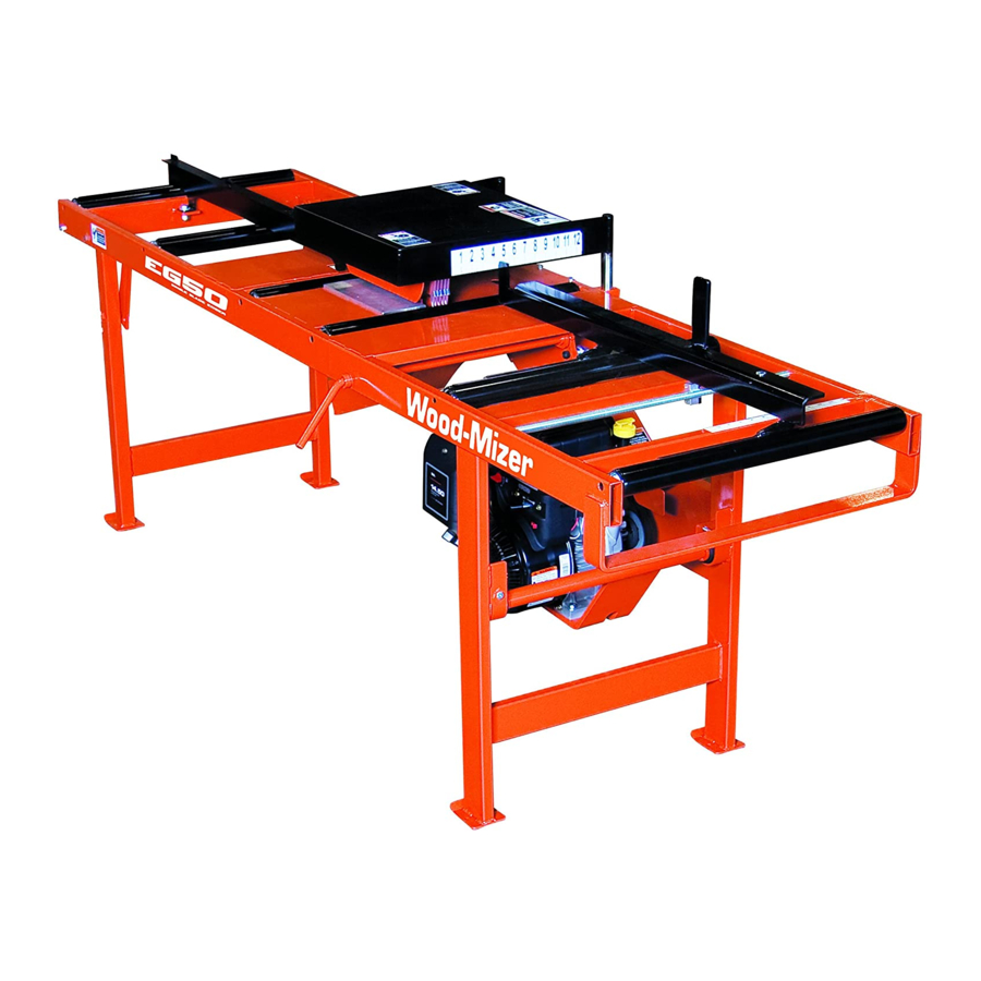
Important components of the edger are identified below. Rear Fence Top Blade Guard Front Fence Rear Leg Lock Bracket Clutch Lever U-Brackets & Engine Lock Pins Assembly SB0001 ® Wood-Mizer is a registered trademark of Wood-Mizer Products, Inc. Introduction SBEdoc072519... -
Page 4: Getting Service
Getting Service Getting Service Wood-Mizer is committed to providing you with the latest technology, best quality and strongest customer service available on the market today. We continually evaluate our customers’ needs to ensure we’re meeting current wood-processing demands. Your com- ments and suggestions are welcome. - Page 5 Brazil Headquarters Europe Headquarters Serving Brazil Serving Europe, Africa, West Asia Wood-Mizer do Brasil Wood-Mizer Industries Sp z o.o. Rua Dom Pedro 1, No: 205 Bairro: Sao Jose Nagorna 114 Ivoti/RS CEP:93.900-000 62-600 Kolo, Poland Tel: +55 51 9894-6461/ +55 21 8030-3338/ +55 51 Phone: +48.63.26.26.000...
-
Page 6: Specifications
Introduction Specifications Specifications Model: SBEG10/EG50G10 Rev. A1.01+ Dimensions Length: 96" Width: 35 3/4" Height: 40" Table Height: 32 5/8" Weight: 373 lbs (480 lbs w/shipping crate) Capacity: Min. Output Width (Fence to Blade): 2" Max. Output Width (Fence to Blade): 12"... -
Page 7: Customer And Equipment Identification
Identification Information (To be filled in by purchaser) Model No. Revision No. Customer No. MFG BY/ FABRIQUÉ PAR: WOOD-MIZER PRODUCTS, INC. 8180 W. 10t h St . Indianapolis, IN 46214-2400 U.S.A. 317/ 271-1542 800/ 553-0182 Model No.: SBEG10 Serial No.:... -
Page 8: Safety
Safety Safety Symbols SECTION 2 SAFETY Safety Symbols The following symbols and signal words call your attention to instructions concerning your personal safety. Be sure to observe and follow these instructions. DANGER! indicates an imminently hazardous situation which, if not avoided, will result in death or serious injury. WARNING! suggests a potentially hazardous situation which, if not avoided, could result in death or serious injury. -
Page 9: Safety Instructions
Wood-Mizer Edger. All Wood-Mizer Edger owners are encouraged to become thoroughly familiar with these appli- cable laws and comply with them fully while using the equipment. - Page 10 Safety Safety Instructions the shipping block from under the blade cover. Failure to do so will cause damage to the machine. SBEdoc072519 Safety...
- Page 11 Safety Safety Instructions Edger Operation Safety DANGER! Make sure all guards and covers are in place and secured before operating or transporting the Edger. Failure to do so may result in serious injury. DANGER! Always keep hands away from moving blade. Blade may still be moving even when the clutch lever is dis- engaged.
- Page 12 Safety Safety Instructions Refueling and Engine Operation Safety DANGER! Always be sure the blade is disengaged and all persons are out of the path of the blade before starting the engine or motor. Failure to do so will result in serious injury. WARNING! Store gasoline away from sawdust and other flammable materials.
-
Page 13: Setup & Operation
Setup & Operation Setup SECTION 3 SETUP & OPERATION Setup CAUTION! Before operating the Edger, be sure to remove the shipping block from under the blade cover. Failure to do so will cause damage to the machine. 1. A shipping block supports the blade guard during factory shipment. Remove this block before operating the Edger. - Page 14 Setup & Operation Setup 3. Install the engine. To install: See Figure 3-2. Position the engine beneath the Edger. Remove the U-bracket lock pins and clutch retaining pin. Raise the clutch handle. Raise clutch handle Remove U-bracket Remove clutch lock pins retaining pin SB0001-11...
- Page 15 Setup & Operation Setup See Figure 3-3. Place the ends of the engine mounting bar in the U-brackets and reinstall the U-bracket lock pins. Position the drive belt around the engine pulley. WARNING! When setting up or transporting the Edger, avoid areas marked as pinch points.
- Page 16 Setup & Operation Setup 5. Adjust the front guide fence: See Figure 3-4. The guide scale shows how many inches the front fence is from the blade. This helps you to determine the width of lumber you will be sawing. For example, if you wish to cut 2"...
-
Page 17: Alignment
Setup & Operation Alignment Alignment Proper machine alignment is important for optimum cutting performance. Check machine alignment often and adjust as necessary. To check: 1. Adjust the front fence to the 5" position. Be sure the blade clutch handle is disengaged. 2. - Page 18 Setup & Operation Alignment 4. Use a C-clamp to secure the string to the rear frame cross tube, maintaining the string alignment to the front fence. 5. Measure the distance between the face of the blade and the string at each end of the blade.
- Page 19 Setup & Operation Alignment 7. Measure the distance between the face of the rear fence and the string at each end of the rear fence. The measurements should be the same as the front fence setting (5 inches). See Figure 3-7. If necessary, loosen the locking nuts and move the rear fence rail as nec- essary.
-
Page 20: Operation
Setup & Operation Operation Operation 1. Make sure the Edger has been properly set up and the blade guard and fences have been properly adjusted to cut your size boards. See Section 3.1. 2. Check the alignment. See Section 3.2. 3. - Page 21 Setup & Operation Operation DANGER! Maintain a clean and clear path for all necessary movement around the Edger and lumber stacking areas. Failure to do so will result in serious injury. CAUTION! Avoid resting boards or other objects on the blade guard.
-
Page 22: Transporting The Edger
Setup & Operation Transporting The Edger Transporting The Edger Follow these steps to transport the Edger in a pickup truck (minimum 8’ bed required): WARNING! When setting up or transporting the Edger, avoid areas marked as pinch points. These are located near the rear folding legs and the engine pulley. -
Page 23: Maintenance
Maintenance Drive System SECTION 4 MAINTENANCE DANGER! Always shut off the engine and allow all moving parts to come to a complete stop before removing any guards or covers. Failure to do so will result in serious injury. Drive System 1. -
Page 24: Feed Table Rollers
Maintenance Feed Table Rollers Feed Table Rollers Check the feed table rollers for wear every 25 hours of operation. Rollers should spin freely, without too much play. To replace, cut the old roller in half and remove it from the edger. -
Page 25: Blade System
Maintenance Blade System Blade System 1. Check the blade every 8 hours of operation. Resharpen or replace as needed. See Figure 4-2. To replace, loosen the two mount knobs and remove the top blade guard. Unscrew and remove the blade filler plate. Raise the lock bracket to lock the blade shaft in place. - Page 26 Maintenance Blade System 3. Lubricate the blade bearings every 400 hours of operation. Use a high-quality synthetic grease such as Amoco Rycon #2 or Chevron SRI #2. See Figure 4-3. Access the bearing grease fittings through the holes in the blade bearing cover plate.
-
Page 27: Replacement Parts
Replacement Parts Edger SECTION 5 REPLACEMENT PARTS Edger SB0001-2 DESCRIPTION ( Indicates Parts Available In Assemblies Only) PART NUMBER QTY. EDGER, EG50 SINGLE BLADE 10HP GAS EG50G10 Edger Parts (See Section 5.2) Engine Parts (See Section 5.7) Replacement Parts SBEdoc072519... -
Page 28: Frame Assembly
STOP! 039358 Always wear eye, ear, respiration and foot protection when operating this machine. Failure to do so may result in injury. Wood-Mizer Products, Inc. 800-525-8100 Reorder #S11753 AVOID RESTING BOARDS OR OTHER OBJECTS ON COVER. DAMAGE MAY RESULT S12639... - Page 29 Decal, Kickback Hazard Warning 038134 Decal, Eye/Ear Warning S11753 Decal, Hand Pinch Warning S12641 Decal, 2 1/2” Wood-Mizer Logo 049401 Decal, EG50 Euro Logo White 062724 Roller, 3/8” ID x 2” OD x 3/4” 007455 Bolt, 3/8-16 x 2 1/2” Hex Head Full Thread F05007-157 Washer, 3/8”...
-
Page 30: Guide Fence Assembly
Replacement Parts Guide Fence Assembly Guide Fence Assembly 9 10 SB0001-4 DESCRIPTION ( Indicates Parts Available In Assemblies Only) PART NUMBER QTY. FENCE WELDMENT, REAR T-BAR 007305 BOLT, 1/2-13 X 1 1/4” HEX HEAD F05008-37 WASHER, 1/2” SAE FLAT F05011-2 NUT, 1/2-13 HEX NYLON LOCK F05010-8 FENCE ASSEMBLY, SINGLE BLADE EDGER... - Page 31 Replacement Parts Guide Fence Assembly Nut, 5/16-18 Hex F05010-17 Spring, Edger Front Fence P04060 Nut, 5/16-18 Hex Lock F05010-6 Bushing, 5/8” ID x 7/8” OD x 1/2” Bronze P05135 SHAFT WELDMENT, EDGER FENCE 007290 BOLT, 1/4-20 X 1/2” SELF-TAPPING HEX HEAD F05015-1 SHAFT WELDMENT, EDGER SETWORKS 007292...
-
Page 32: Rear Leg Assembly
Replacement Parts Rear Leg Assembly Rear Leg Assembly SB0001-5 DESCRIPTION ( Indicates Parts Available In Assemblies Only) PART NUMBER QTY. LEG WELDMENT, EDGER REAR 007183 PLATE, REAR LEG LOCK 007184 WASHER, 3/8” SAE FLAT F05011-3 NUT, 5/16-18 HEX NYLON LOCK F05010-58 WASHER, 1/2”... -
Page 33: Blade Assembly
Replacement Parts Blade Assembly Blade Assembly SB0001-6B DESCRIPTION ( Indicates Parts Available In Assemblies Only) PART NUMBER QTY. SHAFT, EDGER BLADE 007185 BEARING, 1 7/16” BORE PILLOW BLOCK P07981-1 BOLT, 1/2-13 X 2” HEX HEAD GRADE 5 F05008-102 WASHER, 1/2” SAE FLAT F05011-2 NUT, 1/2-13 HEX NYLON LOCK F05010-8... - Page 34 Replacement Parts Blade Assembly BOLT, 5/16-18 X 1/2” SBH F05006-20 PIN, 3/16” X 7/8” ROLL F05012-19 LOCK, BLADE SHAFT 065571 BOLT, 3/8-16 X 3/4” HEX HEAD GRADE 2 F05007-27 WASHER, 3/8” SPLIT LOCK F05011-4 WASHER, 3/8” FLAT SAE F05011-3 Blade 025916 replaces 007187 Rev. A1.03. New blade has wider kerf to eliminate binding with rear T-bar. SBEdoc072519 Replacement Parts...
-
Page 35: Blade Cover Assembly
Replacement Parts Blade Cover Assembly Blade Cover Assembly SB0001-7 DESCRIPTION ( Indicates Parts Available In Assemblies Only) PART NUMBER QTY. COVER ASSEMBLY, EDGER BLADE 007314 Cover Weldment, Edger Blade 007313 Bolt, 3/8-16 x 2 1/2” Hex Head Grade 5 F05007-125 Washer, 3/8”... -
Page 36: Engine Assembly
Replacement Parts Engine Assembly Engine Assembly USE AN APPROPRIATE FUNNEL TO REFUEL TANK. REMOVE ANY SPILLED FUEL FROM AREA BEFORE STARTING ENGINE. S12692 TORQUE TO 95 IN-LBS SB0003-8B DESCRIPTION ( Indicates Parts Available In Assemblies Only) PART NUMBER QTY. ENGINE ASSEMBLY, 10HP EDGER 007192 Engine, 10HP Briggs Gas #2053320246B1 057862... - Page 37 Replacement Parts Engine Assembly Bolt, 5/16-18 x 1 3/4” Hex Head Full Thread Grade 5 F05006-81 Washer, 5/16” SAE Flat F05011-17 Nut, 5/16-18 Hex Nylon Lock F05010-58 Pin, 1/8” x 1 13/16” Safety P05059 Lanyard, 3/64” x 6” 016030 Decal, Engine Refuel Warning S12692 Key, 1/4 x 1 11/16 S04124...
-
Page 38: Index
INDEX maintenance blade system drive system feed table rollers replacement parts blade assembly blade cover edger engine 5-10 frame guide fence rear leg safety instructions symbols service information branch locations customer & equipment ID general contact info specifications setup & operation alignment operation setup...
Need help?
Do you have a question about the SBEG10 and is the answer not in the manual?
Questions and answers