
Related Manuals for RabbitCore RCM2300


Summary of Contents for RabbitCore RCM2300
- Page 1 RabbitCore RCM2300 C-Programmable Module Getting Started Manual 019–0101 • 040515–D...
- Page 2 Z-World reserves the right to make changes and improvements to its products without providing notice. Trademarks Rabbit and Rabbit 2000 are registered trademarks of Rabbit Semiconductor. RabbitCore is a trademark of Rabbit Semiconductor. Dynamic C is a registered trademark of Z-World Inc. Z-World, Inc. Rabbit Semiconductor...
-
Page 3: Table Of Contents
2.2.1 Prototyping Board Features ......................7 2.2.2 Prototyping Board Expansion ......................8 ..................9 2.3 Development Hardware Connections 2.3.1 Attach RCM2300 to Prototyping Board ..................9 2.3.2 Connect Programming Cable .....................10 2.3.3 Connect Power Supply .......................11 ....................12 2.4 Where Do I Go From Here? 2.4.1 Technical Support ........................12... - Page 4 RabbitCore RCM2300...
-
Page 5: Chapter 1. Introduction & Overview
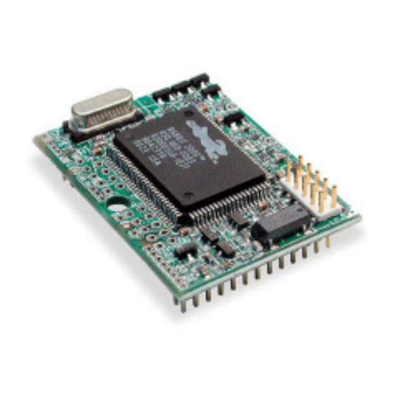
Rabbit 2000 I/O bus lines, address lines, data lines, parallel ports, and serial ports. The RCM2300 receives its +5 V power from the user board on which it is mounted. The RCM2300 can interface with all kinds of CMOS-compatible digital devices through the user board. -
Page 6: Other Factory Versions
Low-power variants of the RCM2300 running at 3.686 MHz and 3.3 V can be custom made in quantity. The clock can be changed dynamically to any one of five frequencies as low as 32 kHz to reduce power consumption even further. -
Page 7: Development Software
Fifteen additional connection points are available along one edge of the RCM2300 board. These connection points are 0.030" diameter holes spaced 0.05" apart. Nineteen additional connection points are available at locations J2 and J3. These additional connection points are reserved for future use. -
Page 8: Using Online Documentation
• If you do not have a suitable printer or do not want to print the manual yourself, most retail copy shops (e.g. Kinkos, CopyMax, AlphaGraphics, etc.) will print the manual from the PDF file and bind it for a reasonable charge—about what we would have to charge for a printed and bound manual. RabbitCore RCM2300... -
Page 9: Chapter 2. Hardware Setup
NOTE: This chapter (and this manual) assume that you have the RabbitCore RCM2300 Development Kit. If you purchased an RCM2300 module by itself, you will have to adapt the information in this chapter and elsewhere to your test and development setup. -
Page 10: Prototyping Board
The Prototyping Board included in the Development Kit makes it easy to connect an RCM2300 to a power supply for development. It also provides some basic I/O peripherals (switches and LEDs), as well as a prototyping area for more advanced hardware develop- ment. -
Page 11: Prototyping Board Features
—Two momentary-contact, normally open switches are con- • nected to the PB2 and PB3 pins of the master RCM2300, and may be read as inputs by sample applications. Two LEDs are connected to the PE1 and PE7 pins of the master RCM2300, and may be driven as output indicators by sample applications. -
Page 12: Prototyping Board Expansion
NOTE: The RS-232 chip, capacitors and header strip are available from electronics dis- tributors such as Digi-Key. —Four I/O pins from the RCM2300 module • Prototyping Board Component Header are hard-wired to the Prototyping Board LEDs and switches through JP1 on the under- side of the Prototyping Board. -
Page 13: Development Hardware Connections
3. Connect the power supply to the Prototyping Board. 2.3.1 Attach RCM2300 to Prototyping Board Turn the RCM2300 module so that the header pins and the mounting hole of the RCM2300 line up with the sockets and mounting hole on the Prototyping Board as shown in Figure 4. -
Page 14: Connect Programming Cable
MASTER position. NOTE: It is important that you line up the pins on headers J4 and J5 of the RCM2300 exactly with the corresponding pins of headers J1 and J2 on the Prototyping Board. The header pins may become bent or damaged if the pin alignment is offset, and the module will not work. -
Page 15: Connect Power Supply
2.3.3 Connect Power Supply When the above connections have been made, you can connect power to the RabbitCore Prototyping Board. Hook the connector from the wall transformer to header J5 on the Prototyping Board as shown in Figure 6. The connector may be attached either way as long as it is not offset to one side. -
Page 16: Where Do I Go From Here
We recommend that you proceed to the next chapter and install Dynamic C (if you do not already have it installed), then run the first sample program to verify that the RCM2300 and the Prototyping Board are set up and functioning correctly. -
Page 17: Chapter 3. Software Installation & Overview
OFTWARE NSTALLATION VERVIEW To develop and debug programs for the RCM2300 (and for all other Z-World and Rabbit Semiconductor hardware), you must install and use Dynamic C. This chapter takes you through the installation of Dynamic C, and then provides a tour of its major features with respect to the RabbitCore RCM2300 module. -
Page 18: System Requirements
• Windows Me • Windows 2000 • Windows XP 3.2.1 Hardware Requirements The PC on which you install Dynamic C for development of RCM2300-based systems should have the following hardware: • A Pentium or later microprocessor • 32 MB of RAM •... -
Page 19: Installing Dynamic C
3.3 Installing Dynamic C Insert the Dynamic C CD-ROM in the drive on your PC. If autorun is enabled, the CD installation will begin automatically. If autorun is disabled or the installation otherwise does not start, use the Windows menu or Windows Explorer to launch from the root folder of the Start >... -
Page 20: Installation Type
(default). Only Dynamic C will be installed. • Compact Installation — You will be allowed to choose which components are • Custom Installation — installed. This choice is useful to install or reinstall just the documentation. RabbitCore RCM2300... -
Page 21: Select Com Port
3.3.3 Select COM Port Dynamic C uses a COM (serial) port to communicate with the target development system. The installation allows you to choose the COM port that will be used. The default selection, as shown in the example above, is COM1. You may select any avail- able port for Dynamic C’s use. -
Page 22: Starting Dynamic C
Board is lit. If it is, check both ends of the programming cable to ensure that it is firmly plugged into the PC and the RCM2300’s programming port, with the pin-1 edge of the cable matched to the pin-1 mark on the board. If you are using the Prototyping Board, ensure that the module is firmly and correctly installed in its connectors. -
Page 23: Sample Programs
To help familiarize you with the RCM2300 modules, Dynamic C includes several sample programs. Loading, executing and studying these programs will give you a solid hands-on overview of the RCM2300’s capabilities, as well as a quick start with Dynamic C as an application development tool. - Page 24 RabbitCore RCM2300...
-
Page 25: Notice To Users
OTICE TO SERS Z-WORLD PRODUCTS ARE NOT AUTHORIZED FOR USE AS CRITICAL COMPONENTS IN LIFE- SUPPORT DEVICES OR SYSTEMS UNLESS A SPECIFIC WRITTEN AGREEMENT REGARDING SUCH INTENDED USE IS ENTERED INTO BETWEEN THE CUSTOMER AND Z-WORLD PRIOR TO USE. Life-support devices or systems are devices or systems intended for surgical implantation into the body or to sustain life, and whose failure to perform, when properly used in accordance with instructions for use provided in the labeling and user’s manual, can be reasonably expected to result in significant injury. - Page 26 RabbitCore RCM2300...
-
Page 27: Index
RCM2300 ......1 features ......6, 7 mounting RCM2300 ....9 optional header JP1 ....8 C language ...... 13, 14 hardware connections ..... 9 install RCM2300 on Prototyp- ing Board ......9 RCM2300 power supply ..... 11 mounting on Prototyping description ....... 1 programming cable ... - Page 28 RabbitCore RCM2300...
-
Page 29: Schematics
CHEMATICS 090-0119 RCM2300 Schematic www.rabbitsemiconductor.com/documentation/schemat/090-0119.pdf 090-0122 RCM2200/RCM2300 Prototyping Board Schematic www.rabbitsemiconductor.com/documentation/schemat/090-0122.pdf 090-0128 Programming Cable Schematic www.rabbitsemiconductor.com/documentation/schemat/090-0128.pdf The schematics included with the printed manual were the latest revisions available at the time the manual was last revised. The online versions of the manual contain links to the latest revised schematic on the Web site. - Page 31 Mouser Electronics Authorized Distributor Click to View Pricing, Inventory, Delivery & Lifecycle Information: DIGI 20-101-0453...
Need help?
Do you have a question about the RCM2300 and is the answer not in the manual?
Questions and answers