
Related Manuals for AOpen AX5TC


Summary of Contents for AOpen AX5TC
- Page 1 AX5TC User's Guide Printed in Taiwan PART NO.:49.87801.211 DOC. NO.:AX5TC-1-E9801A...
- Page 3 AX5TC Mainboard User's Guide Document Number : AX5TC-1-E9801A Model and Revision : For AX5TC revision 1.xx Manual Revision : English, revision A Release Date : Jan 13, 1998 More help for latest information: Taiwan http://www.aopen.com.tw http://www.aopen-usa.com http://www.aopenamerica.com Europe http://www.aopen.nl...
- Page 4 Copyright Copyright © 1998 by this company. All rights reserved. No part of this publication may be reproduced, transmitted, transcribed, stored in a retrieval system, or translated into any language or computer language, in any form or by any means, electronic, mechanical, magnetic, optical, manual or otherwise, without the prior written permission of this company.
- Page 5 Disclaimer This company makes no representations or warranties, either expressed or implied, with respect to the contents hereof and specifically disclaims any warranties, merchantability or fitness for any particular purpose. Any software described in this manual is sold or licensed "as is". Should the programs prove defective following their purchase, the buyer (and not this company, its distributor, or its dealer) assumes the entire cost of all necessary servicing, repair, and any incidental or consequential damages resulting from any defect...
- Page 6 Organization Chapter 1, Overview, covers the introduction and specifications of the system board and special features. Chapter 2, Hardware Installation , describes hardware jumpers, connectors and memory configuration. There are user friendly drawings to locate jumper and connector. Chapter 3, AWARD BIOS, explains the system BIOS and tells how to configure the system by setting the BIOS parameters.
- Page 7 Conventions The following conventions are used in this manual: Text entered user, Represent text input by the user, default settings, default settings and recommended recommended selections selections <Enter>, <Tab>,<Ctl>, <Alt>, Represent the actual keys that you <Ins>, <Del>, etc have to press on the keyboard. Note: Gives bits and pieces of additional information related to the current topic.
-
Page 8: Table Of Contents
Contents Chapter 1 Overview 1.1 Specifications..............4 1.2 Suspend to Hard Drive ............ 6 1.3 0V Modem Wake Up............9 1.4 System Voltage Monitoring .......... 11 1.5 Fan Monitoring ............... 11 1.6 CPU Thermal Protection ..........12 1.7 Multi-language BIOS ............. 13 1.8 PCI Sound Card connector ........... - Page 9 2.3.13 IrDA Connector ............20 2.3.14 SB-LINK..............21 2.3.15 Wake-up Connector ..........22 2.4 Configuring the System Memory ......... 23 Chapter 3 Award BIOS 3.1 Entering the Award BIOS Setup Menu ......2 3.2 Standard CMOS Setup ............ 3 3.3 BIOS Features Setup ............6 3.4 Chipset Features Setup ..........
-
Page 10: Chapter 1 Overview
The most important break through is not only external box modem but also internal modem card can be used to support Modem Wake Up. The AX5TC and MP56 internal modem card implement special circuit (patent applied) to make sure... - Page 11 High Efficient Synchronous Switching Regulator Most of the current switching designs are Asynchronous mode, which from the technical point of view, still consumes very high power as well as heat. AX5TC implements high efficient synchronous switching design that the temperature of MOS FET is far less than Schottky diode of Asynchronous design.
- Page 12 Overview Resetable Fuse AX5TC implements resetable fuses to prevent any accidental short circuit caused by keyboard or USB devices hot plug. PCI Sound Card connector The SB-LINK connector can be used to link Creative-compatible PCI sound card. If you have a Creative PCI sound card installed, it is necessary to link the card to this connector for compatibility issue under DOS environment.
-
Page 13: Specifications
Overview Specifications Form Factor Board Size 305 mm x 208 mm Intel Pentium Processor P54C, PP/MT (P55C), AMD K5/K6 and Cyrix 6x86/M2. System Memory 3V EDO or SDRAM, 168-pin DIMM x3, maximum 256MB. Second-level Cache 512KB pipeline-burst cache onboard Intel 82430TX PCIset Chipset Expansion Slots ISA x4 and PCI x4... - Page 14 VGA and Sound Blaster compatible sound card required. 0V Modem Wake Up Special circuit (patent applied) to support modem wake up by external box modem or internal AOpen F56/MP56 modem card. LAN Wake Up By using a network card that supports this feature...
-
Page 15: Suspend To Hard Drive
16MB HDD space to save your memory image. Note that you have to use VESA compatible PCI VGA (AOpen PV70/PT70), Sound Blaster compatible sound card and sound driver that supports APM (AOpen AW35 or MP56) for Suspend to Hard Drive to work properly. Of course, we recommend to use AOpen products for best compatibility. - Page 16 Overview Option2: Use /partiton switch (applied to FAT16/FAT32 file system): To create a separate partiton for Suspend to Hard Drive, please make sure you have allocated a free partition. We suggest you reserve the free partition which space is appropriate for your future memory expansion. For example, if you have 32MB of system memory and 4MB of VGA memory currently, but you plan to upgrade system memory to 64MB in the near future, then you may reserve a 68MB (64MB+4MB) space by using a disk...
- Page 17 Overview Tip: Following VGA card have been tested & recognized as VESA compatible VGA device. AOpen PV90 (Trident 9680) AOpen PT60 (S3 Virge/BIOS R1.00-01) AOpen PV60 (S3 Tiro64V+) AOpen PT70 (S3 Virge/DX) ProLink Trident GD-5440 ProLink Cirrus GD-5430 ProLink Cirrus GD-5446...
-
Page 18: Modem Wake Up
Modem Wake Up, but if you use external modem, you have to keep the box modem always power-on. AOpen AX5TC and internal modem card implement special circuit (patent applied) and make sure the modem card works properly without any power. We recommend you choose AOpen modem card (MP56) for Modem Wake Up applications. - Page 19 Overview For Internal Modem Card (AOpen MP56): 1. Go into BIOS setup , Power Management à Modem Wake Up, select Enable. 2. Setup your application, put into Windows 95 StartUp or use Suspend to Hard Drive function. 3. Turn system power off by soft power switch.
-
Page 20: System Voltage Monitoring
Overview System Voltage Monitoring This motherboard implements a voltage monitoring system. As you turn on your system, this smart design will continue to monitor your system working voltage. If any of the system voltage is over the component's standard. There will be alarm through application software such as Hardware Monitor utility for a warning to user. -
Page 21: Cpu Thermal Protection
When temperature is higher than a predefined value, the CPU speed will automatically slow down and there will be warning from BIOS and also ADM (AOpen Desktop Manager, similar as Intel LDCM) or Hardware Monitor utility software. ADM is a very powerful network and hardware monitor software. If you do not need network monitor function, you may also use Hardware Monitor utility, which is a small utility for hardware monitoring. -
Page 22: Multi-Language Bios
BIOS. You may download and reflash a specified BIOS version from AOpen 's web site (For example, Chinese). After entering BIOS Setup, you can switch to another language by pressing F9. -
Page 24: Chapter 2 Hardware Installation
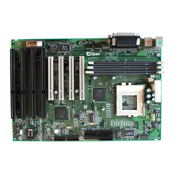
Hardware Installation Jumper and Connector Locations The following figure shows the locations of the jumpers and connectors on the system board : BIOS IrDA COM2 COM1 PRINTER SB-LINK PS/2 MS DIMM3 DIMM2 DIMM1 FAN1 FAN2 PWR2 SPWR MODEM WKUP FAN3 JP14 IDE2 PANEL... - Page 25 Hardware Installation Jumpers: SW1: DIP Switch for CPU voltage and clock ratio JP4,JP5,JP6: CPU external (bus) clock JP14: Clear CMOS Connectors: PS2 MS: PS/2 mouse connector KB2: PS/2 keyboard connector COM1: COM1 connector COM2: COM2 connector PRINTER: Printer connector PWR2: ATX power connector USB: USB connector...
-
Page 26: Jumpers
Hardware Installation Jumpers Jumpers are made by pin headers and plastic connecting caps for the purpose customizing your hardware. Doing so requires basic knowledge of computer hardware, be sure you understand the meaning of the jumpers before you change any setting. The onboard jumpers are normally set to their default with optimized settings. -
Page 27: Setting The Cpu Voltage
Hardware Installation 2.2.1 Setting the CPU Voltage Vcore SW1 is used to select CPU core voltage (Vcore) and ratio, there 3.52V are totally eight switches on the 3.45V DIP. After installing CPU, remember to set the switch 4-8 3.2V to specify a proper Vcore. 2.9V 2.8V 2.2V... - Page 28 Hardware Installation Following table lists possible settings of current CPU available on the market. Note that the correct setting may vary because of new CPU product, refer to your CPU specification for more details. Type Vcore INTEL P54C Single Voltage 3.45V INTEL P55C Dual Voltage...
- Page 29 Hardware Installation This motherboard supports the CPU core voltage from 1.3V to 3.5V, that can be applied to the various CPU type in future. For your reference, all settings are listed in the following table. Vcore 1.30V 1.35V 1.40V 1.45V 1.50V 1.55V 1.60V...
-
Page 30: Selecting The Cpu Frequency
Hardware Installation 2.2.2 Selecting the CPU Frequency CPU Frequency Intel Pentium, Cyrix 6x86 and AMD K5/K6 CPU are designed Ratio to have different Internal (Core) 1.5x (3.5x) and External (Bus) frequency. The ratio of Core/Bus frequency 2.5x (1.75x) is selected by the switch 1-3 of SW1. - Page 31 Hardware Installation CPU External Clock JP4, JP5 and JP6 are the selections of CPU external 60MHz clock (bus clock), which is 66MHz actually clock from 75MHz clock generator. 83.3MHz JP4 & JP5 & JP6 JP4 & JP5 & JP6 1 2 3 1 2 3 60MHz 66MHz...
- Page 32 Hardware Installation Pentium Frequency Bus Clock P54C 90 90MHz = 1.5x 60MHz OFF OFF OFF 2-3 & 1-2 & 1-2 P54C 100 100MHz = 1.5x 66MHz OFF OFF OFF 1-2 & 1-2 & 1-2 P54C 120 120MHz = 60MHz OFF OFF 2-3 & 1-2 & 1-2 P54C 133 133MHz = 66MHz...
- Page 33 Hardware Installation PR90 90MHz = 1.5x 60MHz OFF OFF OFF 2-3 & 1-2 & 1-2 PR100 100MHz = 1.5x 66MHz OFF OFF OFF 1-2 & 1-2 & 1-2 PR120 90MHz = 1.5x 60MHz OFF OFF OFF 2-3 & 1-2 & 1-2 PR133 100MHz = 1.5x...
-
Page 34: Clearing The Cmos
Hardware Installation 2.2.3 Clearing the CMOS JP14 Clear CMOS You need to clear the CMOS if you forget your system password. To clear the CMOS, Normal operation (default) follow the procedures listed below: Clear CMOS JP14 JP14 Normal Operation Clear CMOS (default) The procedure to clear CMOS: Turn off the system and unplug the AC power. -
Page 35: Connectors
Hardware Installation Connectors 2.3.1 Power Cable The ATX power supply uses 20-pin connector shown below. Make sure you plug in the right direction. Caution: Make sure that the power supply is off before connecting or disconnecting the power cable. 5V SB 3.3V 3.3V PWR2... -
Page 36: Fan
Hardware Installation 2.3.3 Fan Plug in the fan cable to the fan connectors onboard. The fan connectors are marked FAN1, FAN2 and FAN3 on the system board. You can plug the CPU fan cable to both the 2-pin fan connector FAN1 and the 3-pin fan connector FAN2. -
Page 37: Keyboard
Hardware Installation 2.3.5 Keyboard The onboard PS/2 keyboard connector is a 6-pin Mini-Din connector marked KB2. The view angle of drawing shown here is from back panel of the housing. PS/2 KB 2.3.6 Serial Devices (COM1/COM2) The onboard serial connectors are 9-pin D-type connector on the back panel of mainboard. -
Page 38: Printer
Hardware Installation 2.3.7 Printer The onboard printer connector is a 25-pin D-type connector marked PRINTER. The view angle of drawing shown here is from back panel of the housing. PRINTER 2.3.8 USB Device You can attach USB devices to the USB connector. The mothermoard contains two USB connectors, which are marked as USB. -
Page 39: Ide Hard Disk And Cd Rom
Hardware Installation 2.3.10 IDE Hard Disk and CD ROM This motherboard supports two 40-pin IDE connectors marked as IDE1 and IDE2. IDE1 is also known as primary channel and IDE2 as secondary channel, each channel supports two IDE devices that makes total of four devices. -
Page 40: Hard Disk Led
Hardware Installation IDE2 (Secondary Channel) Slave Master (4th) (3rd) IDE1 (Primary Channel) Slave Master (2nd) (1st) 2.3.11 Hard Disk LED Description The HDD LED connector is marked as HDD HDD LED LED on the board. This connector is designed for different type of housing, actually only two pins are necessary for the LED. -
Page 41: Panel Connector
Hardware Installation 2.3.12 Panel Connector The Panel (multifunction) connector is a 20- pin connector marked as PANEL on the board. Attach the power LED, keylock, KEYLOCK speaker, reset switch Reserved corresponding pins as shown in the figure. RESET POWER LED Some housings have a five-pin connector SPEAKER for the keylock and power LED Since power... -
Page 42: Irda Connector
Hardware Installation Note: If your housing comes with Turbo switch and Turbo LED connectors, you may use these connectors for Suspend switch and Green mode LED functions, respectively. Note: Pressing the Suspend switch allows you to manually force the system to suspend mode. However, this is possible only if the Power Management function in the BIOS Setup menu is enabled. -
Page 43: Sb-Link
Hardware Installation 2.3.14 SB-LINK Description SB-LINK is used to connect Creative PCI sound GNT# card. If you have a Creative PCI sound card installed, it is necessary to link the card to this connector for compatibility issue under DOS environment. REQ# SIRQ# SB-LINK... -
Page 44: Wake-Up Connector
Internal Modem card consumes no power when RING system power is off, it is recommended to use Internal Modem. To use AOpen MP56, connect 4-pin cable from RING connector of MP56 to WKUP connector on the mainboard. Note: Wake-Up Connector and Modem Ring-On are patent applied. - Page 45 Hardware Installation DIMM modules can be identified by following factors: I. Size: single side, 1Mx64 (8MB), 2Mx64 (16MB), 4Mx64 (32MB), 8Mx64 (64MB), 16Mx64 (128MB), and double side, 1Mx64x2 (16MB), 2Mx64x2 (32MB), 4Mx64x2 (64MB), 8Mx64x2 (128MB). Tip: Here is a trick to check if your DIMM is single-side or double-side -- if there are traces connected to golden finger pin 114 and pin 129 of the DIMM, the DIMM is probably double-side;...
- Page 46 Hardware Installation Tip: To identify 2-clock and 4-clock SDRAM, you may check if there are traces connected to golden finger pin 79 and pin 163 of the SDRAM. If there are traces, the SDRAM is probably 4-clock; Otherewise, it is 2-clock. V.
- Page 47 Time. It is similar as CAS Access Time of EDO DRAM and is calculated as number of clock state. The SDRAM that AOpen had tested are listed below. If your SDRAM has unstable problem, go into BIOS "Chipset Features Setup", change CAS Latency Time to 3 clocks.
- Page 48 Hardware Installation Following table list the recommended DRAM combinations of DIMM: DIMM Bit size Single/ Chip DIMM size Recommended Data chip per side Double side count 1M by 16 1Mx64 1M by 16 1Mx64 16MB 2M by 8 2Mx64 16MB 2M by 8 2Mx64 32MB...
- Page 49 Hardware Installation The EDO and SDRAM that AOpen had tested are listed below. Size/Type Vendor Model Single/DoubleChip Count 8M/EDO Micron MT4LCM16E5TG6 16M/EDO Micron MT4LC2M8E7DJ-6 16M/EDO Hitachi 51W17805BJ6 32M/EDO Hitachi 51W17405BLTS6 64M/EDO Hyndai HY51V65804 TC-60 8M/SDRAM KM416511220AT-G12 8M/SDRAM TMS626162DGE M-67 8M/SDRAM...
-
Page 50: Chapter 3 Award Bios
Chapter 3 Award BIOS This chapter tells how to configure the system parameters. You may update your BIOS via AWARD Flash Utility. Important: Because the BIOS code is the most often changed part of the mainboard design, the BIOS information contained in this chapter (especially the Chipset Setup parameters) may be a little different compared to the actual BIOS that came with your mainboard. -
Page 51: Entering The Award Bios Setup Menu
AWARD BIOS Entering the Award BIOS Setup Menu The BIOS setup utility is a segment of codes/routines residing in the BIOS Flash ROM. This routine allows you to configure the system parameters and save the configuration into the 128 byte CMOS area, (normally in the RTC chip or directly in the main chipset). -
Page 52: Standard Cmos Setup
AWARD BIOS Standard CMOS Setup The "Standard CMOS Setup" sets the basic system parameters such as the date, time, and the hard disk type. Use the arrow keys to highlight an item and to select the value for each item. Standard CMOS à... - Page 53 AWARD BIOS Standard CMOS à Primary Master à Type Standard CMOS à Primary Slave à Type Standard CMOS à Secondary Master à Type Standard CMOS à Secondary Slave à Type Type This item lets you select the IDE hard disk parameters that your system supports.
- Page 54 AWARD BIOS Standard CMOS à Drive A Standard CMOS à Drive B These items select floppy drive type. The available settings Drive A and types supported by the mainboard are listed on the None left. 360KB 5.25" 1.2MB 5.25" 720KB 3.5" 1.44MB 3.5"...
-
Page 55: Bios Features Setup
AWARD BIOS BIOS Features Setup This screen appears when you select the option "BIOS Features Setup" from the main menu. BIOS Features à Virus Warning Virus Warning Set this parameter to Enabled to activate the warning message. This feature protects the boot sector and partition Enabled table of your hard disk from virus intrusion. - Page 56 AWARD BIOS BIOS Features à External Cache External Cache Enabling this parameter activates the secondary cache (currently, PBSRAM cache). Disabling the parameter Enabled slows down the system. Therefore, we recommend that Disabled you leave it enabled unless you are troubleshooting a problem.
- Page 57 AWARD BIOS BIOS Features à Boot-up Floppy Seek When enabled, the BIOS issues the seek command to the Boot-up Floppy floppy drive during POST to move floppy drive head Seek forward and backward. Enabled Disabled BIOS Features à Boot-up NumLock Status Boot-up NumLock Setting this parameter to On enables the numeric function Status...
- Page 58 AWARD BIOS BIOS Features à Typematic Delay Typematic Delay This parameter allows you to control the delay time between the first and the second keystroke (where the repeated keystrokes begin). The typematic delay settings are 250, 500, 750, and 1000 msec. 1000 BIOS Features à...
- Page 59 AWARD BIOS BIOS Features à Video BIOS Shadow Video BIOS VGA BIOS Shadowing means to copy video display Shadow card BIOS into the DRAM area. This enhances system performance because DRAM access time is faster than Enabled ROM. Disabled BIOS Features à C800-CBFF Shadow BIOS Features à...
-
Page 60: Chipset Features Setup
AWARD BIOS Chipset Features Setup The "Chipset Features Setup" includes settings for the chipset dependent features. These features are related to system performance. Caution: Make sure you fully understand the items contained in this menu before you try to change anything. You may change the parameter settings... - Page 61 AWARD BIOS Chipset Features à Auto Configuration Auto Configuration When Enabled , the DRAM and cache related timing are set to pre-defined value according to CPU type Enabled and clock. Select Disable if you want to specify your Disabled own DRAM timing. Chipset Features à...
- Page 62 AWARD BIOS Chipset Features à DRAM Read Burst (EDO/FP) DRAM Read Burst Read Burst means to read four continuous memory (EDO/FP) cycles on four predefined addresses from the DRAM. The default value is x222/x333 for 60ns EDO or FPM x444/x444 (Fast Page Mode) DRAM.
- Page 63 AWARD BIOS Chipset Features à DRAM Page Idle Timer DRAM Page Idle This item determines the amount of time in CPU Timer clocks that DRAM page will be close after CPU becomes idle. 2 Clks 4 Clks 6 Clks 8 Clks Chipset Features à...
- Page 64 AWARD BIOS Chipset Features à Video BIOS Cacheable Video BIOS Allows the video BIOS to be cached to allow faster Cacheable video performance. Enabled Disabled Chipset Features à 8 Bit I/O Recovery Time 8 Bit I/O Recovery For some old I/O chips, after the execution of an I/O Time command, the device requires a certain amount of time (recovery time) before the execution of the next...
- Page 65 AWARD BIOS Chipset Features à PCI Passive Release PCI Passive Release This item lets you control the Passive Release function of the PIIX4 chipset (Intel PCI to ISA bridge). Enabled This function is used to meet latency of ISA bus Disabled master.
-
Page 66: Power Management Setup
AWARD BIOS Power Management Setup The Power Management Setup screen enables you to control the mainboard ’s green features. See the following screen. Power Management à Power Management Power Management This function allows you to set the default parameters of power-saving modes. Set to Disable to turn off Max Saving power management function. - Page 67 AWARD BIOS Power Management à PM Controlled by APM PM Controlled by If "Max Saving" is selected, you can turn on this item, transfer power management control (Advanced Power Management) and enhance power saving function. For example, stop CPU internal clock.
- Page 68 AWARD BIOS Power Management à Standby Mode Standby Mode This item lets you set the period of time after which the system enters into Standby mode. In this mode, Disabled CPU clock slows down, hard disk will be shut off and 1 Min the monitor power-saving feature activates.
- Page 69 It does not like traditional green PC suspend mode, the system can be true power off, (identified by the fan of your power supply is off). You can use external box modem or AOpen MP56/F56 internal modem card modem ring-on,...
- Page 70 AWARD BIOS Power Management à Throttle Duty Cycle Throttle Duty Cycle Clock Throttling means at the Doze/Standby state, the CPU clock count in a given time (not the 2.5 % frequency) is reduced to the ratio specified in this 25.0 % parameter.
- Page 71 AWARD BIOS Power Management à RTC WakeUp Timer RTC WakeUp Timer The RTC WakeUp Timer can be programmed at a specified date/time to wakeup the system. The Disabled Date/Time is set by " WakeUp Date (of Month)" and Wake Up "WakeUp Time (hh:mm:ss)".
- Page 72 AWARD BIOS Power Management à IRQ [3-7,9-15],NMI IRQ [3-7,9-15],NMI To enable or disable the detection of IRQ3-7, IRQ9- 15 or NMI interrupt events for power down state Enabled transition. Disabled Power Management à Primary IDE 0 Power Management à Primary IDE 1 Power Management à...
-
Page 73: Pnp/Pci Configuration Setup
AWARD BIOS PNP/PCI Configuration Setup The PNP/PCI Configuration Setup allows you to configure the ISA and PCI devices installed in your system. The following screen appears if you select the option "PNP/PCI Configuration Setup" from the main menu. PNP/PCI Configuration à PnP OS Installed PnP OS Installed Normally, the PnP resources are allocated by BIOS during POST (Power-On Self Test). - Page 74 AWARD BIOS PNP/PCI Configuration à Resources Controlled By Resources Controlled Setting this option to Manual allows you to individually assign the IRQs and DMAs to the ISA and PCI devices. Set this to Auto to enable the auto- Auto configuration function. Manual PNP/PCI Configuration à...
- Page 75 AWARD BIOS PNP/PCI Configuration à DMA 0 PNP/PCI Configuration à DMA 1 PNP/PCI Configuration à DMA 3 PNP/PCI Configuration à DMA 5 PNP/PCI Configuration à DMA 6 PNP/PCI Configuration à DMA 7 If your ISA card is not PnP compatible and requires a DMA 0 special DMA channel to support its function, set the Legacy ISA...
- Page 76 AWARD BIOS Slot 1 INTA INTB INTC INTD Slot 2 INTB INTC INTD INTA Slot 3 INTC INTD INTA INTB Slot 4 INTD INTA INTB INTC Slot 5 (if any) INTD INTA INTB INTC PNP/PCI Configuration à Used MEM Base Addr This item, in conjunction with the "Used MEM Used MEM base addr Length", lets you set a memory space for non-PnP...
-
Page 77: Load Setup Defaults
The "Load Turbo Defaults" option gives better performance than Optimal values. However, Turbo values may not be the best setting of this mainboard but these values are qualified by the AOpen RD and QA department as the reliable settings especially if you have limited loading of add-on card and memory size (for example, a system that contains only a VGA/Sound card and two SIMMs). -
Page 78: Integrated Peripherals
AWARD BIOS Integrated Peripherals The following screen appears if you select the option "Integrated Peripherals" from the main menu. This option allows you to configure the I/O features. Integrated Peripherals à IDE HDD Block Mode IDE HDD Block This feature enhances disk performance by allowing Mode multisector data transfers and eliminates the interrupt handling time for each sector. - Page 79 AWARD BIOS Integrated Peripherals à IDE Primary Master PIO Integrated Peripherals à IDE Primary Slave PIO Integrated Peripherals à IDE Secondary Master PIO Integrated Peripherals à IDE Secondary Slave PIO IDE Primary Master Auto Setting this item to activates the HDD speed auto-detect function.
- Page 80 AWARD BIOS Integrated Peripherals à USB Legacy Support USB Legacy Support This item lets you enable or disable the USB keyboard driver within the onboard BIOS. The Enabled keyboard driver simulates legacy keyboard command Disabled and let you use USB keyboard during POST or after boot if you don't have USB driver in the operating system.
- Page 81 AWARD BIOS Integrated Peripherals à Onboard Serial Port 1 Integrated Peripherals à Onboard Serial Port 2 Onboard Serial Port 1 This item allow you to assign address and interrupt for the board serial port. Default is Auto . Auto 3F8/IRQ4 2F8/IRQ3 3E8/IRQ4 2E8/IRQ3...
- Page 82 AWARD BIOS Integrated Peripherals à Onboard Parallel Port Onboard Parallel This item controls the onboard parallel port address Port and interrupt. 3BC/IRQ7 378/IRQ7 278/IRQ7 Disabled Note: If you are using an I/O card with a parallel port, make sure that the addresses and IRQ do not conflict.
-
Page 83: Password Setting
AWARD BIOS 3.10 Password Setting Password prevents unauthorized use of your computer. If you set a password, the system prompts for the correct password before boot or access to Setup. To set a password: At the prompt, type your password. Your password can be up to 8 alphanumeric characters. -
Page 84: Exit Without Saving
3.15 BIOS Flash Utility The BIOS Flash utility allows you to upgrade the system BIOS. To get the AOpen Flash utility and the upgrade BIOS file, contact your local distributor or visit our homepage at http://www.aopen.com.tw . Please make sure that you have the correct BIOS ready, the BIOS filename is normally like AP5TR110.BIN, which means model AP5T BIOS revision 1.10. - Page 85 AWARD BIOS [AOFLASH.EXE] This utility will try to check the mainboard model, BIOS version and Super/Ultra IO chip model. To ensure the correct BIOS file for the correct mainboard and IO chip. This utility will permanently replace your original BIOS content after flashing.
- Page 86 Appendix C Jumper Table Summary Setting the CPU Voltage CPU Core Voltage 3.52V (Cyrix 6x86 or AMD K5) 3.45V (Intel P54C or IDT C6) 3.2V (AMD K6-233) 2.9V (K6-166/200 or M2) 2.8V (Intel P55C) 2.2V (AMD K6-266/300) 1.8V (For future use) Type Vcore INTEL P54C...
- Page 87 Jumper Table Summary Tip: Normally, for single voltage CPU, Vcpuio (CPU I/O Voltage) is equal to Vcore, but for CPU that needs dual voltage such as PP/MT (P55C) or Cyrix 6x86L, Vcpuio is different from Vcore and must be set to Vio (PBSRAM and Chipset Voltage). The single or dual voltage CPU is automatically detected by hardware circuit.
- Page 88 Jumper Table Summary Pentium Frequency Bus Clock P54C 90 90MHz = 1.5x 60MHz OFF OFF OFF 2-3 & 1-2 & 1-2 P54C 100 100MHz = 1.5x 66MHz OFF OFF OFF 1-2 & 1-2 & 1-2 P54C 120 120MHz = 60MHz OFF OFF 2-3 &...
- Page 89 Jumper Table Summary Frequency Bus Clock PR2-166 166MHz = 2.5x 66MHz OFF 1-2 & 1-2 & 1-2 PR2-200 200MHz = 66MHz OFF ON OFF 1-2 & 1-2 & 1-2 PR2-233 233MHz = 3.5x 66MHz OFF OFF OFF 1-2 & 1-2 & 1-2 PR2-266 266MHz= 66MHz...
- Page 90 Tip: There are many useful information in our homepage, such as jumper settings, latest BIOS, drivers, and more FAQs. Visit our homepage to see if there is answer of your problem. Taiwan http://www.aopen.com.tw http://www.aopen-usa.com http://www.aopenamerica.com Europe http://www.aopen.nl No display Check all jumper settings according to section 2.2 "Jumpers".
- Page 91 Troubleshooting the problem is your add-on cards or peripheral. try to reinstall the add-on cards one by one to find out which card is causing the problem. Check the monitor and VGA cable. Press the <Num Lock> key to enable/disable the Num Lock function. If the Num Lock LED works properly, this indicates that your CPU, SIMM and BIOS bootup sequence are properly functioning.
- Page 92 Troubleshooting If your CPU bus frequency is 66MHz, set the CPU external/bus frequency to 60MHz, but leave the CPU core/bus frequency ratio unchanged. Normally, CPU with 66MHz bus frequency works properly at slower speed, e.g., 60MHz. This will help you identify if the CPU is remarked or if the mainboard or add-on card is unstable at 66MHz.
- Page 93 Refer to Chapter 3 "Advanced CMOS Setup" section. Some applications has trouble at higher system speed. Visit our WWW home page, (address http://www.aopen.com.tw ) , check the FAQ area (frequently asked question) and download the latest BIOS, try again with the latest BIOS.
- Page 94 Troubleshooting Technical Problem Report Form Name: FROM: TEL: FAX: Email address: Error Symptom: q PS/2 mouse q COM1/COM2, serial mouse. Error Type: q Printer q Parallel Tape (Please mark in the box and list q Floppy q Floppy Tape the model and q IDE HDD q IDE CDROM version below.)
-
Page 95: Appendix A Frequently Asked Question
BIOS revision Q: How can I identify version of the mainboard? A: The AOpen mainboard revision appears as Rev x.x on the PCB, near the PCI slot. For example, for AP5T revision 3.4, the revision number appears on the PCB as follows: AP5T revision 3.4... - Page 96 Frequently Asked Questions Q: What is FCC DoC (Declaration of Conformity)? A: The DoC is new certification standard of FCC regulations. This new standard allows DIY component (such as mainboard) to apply DoC label separately without a shielding of housing. The rule to test mainboard for DoC is to remove housing and test it with regulation 47 CFR 15.31.
- Page 97 EPROM (Erasable Programmable ROM), if BIOS has to be upgraded, you need to remove EPROM from mainboard, clear by ultra-violet (UV) light, re- program, and then insert back.. AOpen mainboards use much easier Flash ROM, only Flash ROM programming utility is necessary, no need to open housing and change the BIOS ROM.
- Page 98 This feature allows you to immediately resume to your original work without the long time waiting from bootup, entering Win95 and running Winword. The AX5TC with Intel TX chipset can support ACPI. Q: What is ATX Soft Power On/Off and Momentary Switch? A: The Soft Power On of the ATX specification means to provide a standby current for special circuit to wait for wakeup event when main power is off.
- Page 99 Q: What is ADM (Advanced Desktop Manager)? A: This is a desktop client and server management software developed by AOpen. It is similar as Intel LDCM with some improvement. ADM is not only for corporate network management, it can also be used as system status monitoring utility, for example, CPU fan, thermal and system voltage monitoring.
- Page 100 HP Open View) Remote File Transfer Q: Why the AOpen mainboards (MB) do not have cache module expansion slot? A: Faster CPU speed requires more difficult and complex MB timing design. Every trace and components delay must be taken into consideration. The...
Need help?
Do you have a question about the AX5TC and is the answer not in the manual?
Questions and answers