Kirisun DR600 Service Manual
Hide thumbs
Also See for DR600:
- Instruction manual (25 pages) ,
- Instruction manual (13 pages) ,
- Instruction manual (15 pages)
Table of Contents
Advertisement
Advertisement
Table of Contents

Related Manuals for Kirisun DR600


Summary of Contents for Kirisun DR600
-
Page 2: Table Of Contents
DR600 Service Manual Contents Overview ..............................1 Scope of Manual ............................ 1 Safey Precautions ..........................1 Product Controls and LED Indicator Introduction................2 Product Controls ............................ 2 LED Indicators ............................3 Circuit Description ..........................4 RF Circuit ............................... 4 3.1.1 Tx Circuit ............................. - Page 3 DR600 Service Manual Preparation ............................40 Method of Modulation and Test ......................40 6.2.1 Local Oscillator Adjustment....................... 40 6.2.2 Tx Adjustment ........................... 41 6.2.3 Rx Adjustment ........................... 42 Main Technical Functions and Specifications ................... 44 Maintenance and Test Equipment ....................... 46 Troubleshooting ............................
- Page 4 DR600 Service Manual Figure 20 136-174 Power Amplifier Module Schematic Diagram ..............143 Figure 21 Baseband Mainboard Schematic Diagram .................. 146 Figure 22 Front Pannel Schemetic Diagram ....................161 Figure 23 Power Board Schemetic....................... 162 Figure 24 Accessory Schematic Diagram ....................163...
-
Page 5: Overview
This manual is intended for use by trained engineers and professional technicians for the maintenance and repair of DR600 Repeater. Data changes in this manual may occur with the improvement of technology. To get the latest technology information, please contact us or your local distributors. -
Page 6: Product Controls And Led Indicator Introduction
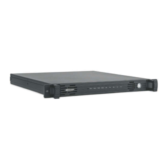
DR600 Service Manual 2. Product Controls and LED Indicator Introduction 2.1 Product Controls The appearance of the the DR600 repeater is shown in the Figure 2-1. Figure 2-1 DR600 Appearance Part Name Part Name Handle LED Indicator Power Switch Grouding Rod 100~240V AC port 13.6V DC port... -
Page 7: Led Indicators
DR600 Service Manual 2.2 LED Indicators LED Indicator Description TX-A Indicates slot 1 is transmitting. RX-A Indicates slot 1 is receiving. TX-B Indicates slot 2 is transmitting. RX-B Indicates slot 2 is receiving. Repeater mode. When illuminated, the repeater is active. When the repeater is inactive, the LED is off. -
Page 8: Circuit Description
DR600 Service Manual 3. Circuit Description 3.1 RF Circuit The RF part is composed of transmitter module, power amplifier module and receiver module. 3.1.1 Tx Circuit Figure 3-1 Transmitter Circuit TXENABLE TXLD MODEIN SDATA IC100 SKY72310 SCLK TXPLLCS Q105 X100... -
Page 9: Rf Power Amplifier Module Circuit
DR600 Service Manual The 12.8 MHz reference clock (X100) output signal which is controlled by MODE1 signal will enter the reference input port of PLL IC (IC100 SKY72310), then according to the configuration of register, it will be divided to get 3.2MHz reference frequency, and the frequency will be compared in phase difference with the signal generated by the frequency division which is resulted from the VCO’s enter into the input port of PLL... -
Page 10: Rx Module Circuit
DR600 Service Manual APC and Stationary Wave Protection Circuit The directional coupler detects the forward and reverse directions RF signal and passes the Q103,Q104 to convert the signal to the DC voltage which is corresponding to the forwardand reverse direction power. - Page 11 DR600 Service Manual IF Processor Circuit Figure 3-4 IF Processor The 51.65MHz IF signal output from the IF amplifier enters the AD9864 via its pin 47, and it finishes the second frequency mixing in the AD9864 to convert the fisrt IF to the second IF. The second IF signal is converted to the digital signal through the ADC sampling and output from the SSI port, and the digital signal is sent to FPGA for demodulation.
-
Page 12: Gps Ciruit
DR600 Service Manual and some other components, while while the VCO covers the band of 383.35~418.35MHz (VHF is 103.35~122.35MHz) is composed of D1002~D1005、L1016、Q1009 and some other components. 3.2 GPS Ciruit Figure 3-5 GPS Schematic Diagram As Figure 3-5 shows, the repeater baseband board includes the GPS module (U9) and the GPS antenna interface J8(SMA). -
Page 13: Baseband Section
DR600 Service Manual 3.3 Baseband Section 3.3.1 Circuit Description Figure 3-6 Baseband Circuit As Figure 3-6 shows, inside the dotted line box is the baseband section circuits, which includes the four major modules of dual core processor(U4), DDR2(U6), NAND FLASH(U7) and FPGA (U14). They are used... - Page 14 DR600 Service Manual Figure 3-7 Processor Internal Circuit The internal circuit of the processor is as Figure 3-7 shows, which is composed of various serial interfaces such as 300MHz ARM926EJ MPU、 300MHz C674x DSP、 DMA controller、 SDRAM EMIF interface、 EMAC Ethernet IC RMII interface、McASP digital audio interface and McBSP, SPI, I2C, UART.
-
Page 15: Power Section
DR600 Service Manual index testing. The output power of audio power amplifier (U31) is 1W, which is used for local monitoring or tested speech output. Network interface (U17) is the TRx components of 10/100M single Ethernet physical layer, and it is used ... - Page 16 DR600 Service Manual When AC power supply is off, the electric relay (U1) is released. The DC is connected to U2 via the electric relay (U1) contact. If the panel switch (J5) is on, the electric relay U2 will be switched on, so is the repeater.
- Page 17 DR600 Service Manual Baseband Board Power Supply Figure 3-10 Baseband Board Power Supply Distribution Diagram As Figure 3-10 shows, the baseband and RF employs isolated power supply. B13V will be divided into three paths. One path provides power for baseband circuit, the second one is provided for Tx and Rx module after being isolated by magnetic bead, and the last one is provided for heat dissipation fan after being isolated by the ferrite Inductor.
-
Page 18: Audio Processing
DR600 Service Manual provide it for the analog power of CODEC (U30). 3.3.3 Audio Processing Figure 3-11 Audio Processing Schematic Diagra As the Figure 3-11 shows, the audio processing module mainly achieves encoding and decoding with ADC and DAC of the audio signal, including air audio forwarding and local audio TRx. -
Page 19: Ethernet Interface
DR600 Service Manual internal DSP. In the meantime, converts the received digital audio from the internal DSP to analog audio, then send the audio to audio power amplifier(U31), before finally send to the ACCY external interface, which is to drive the 1W, 16Ω speaker. -
Page 20: Hardware Version Encode
DR600 Service Manual Figure 3-13 Firmware Download Mode Figure 3-14 User Mode As showing in Figure 3-14, the level of boot 1 to boot4 is 1110, and it enters to normal running user mode after power on. It starts from NAND FLASH. In this mode, it can upgrade operation system kernel, device driver program, files system and application program by network interface. -
Page 21: Baseband Board Interface And Indicator
DR600 Service Manual Ver6.0 NULL NULL NULL Ver7.0 NULL NULL NULL 3.3.7 Baseband Board Interface and Indicator Figure 3-16 Baseband Board Interface and Indicator See Figure 3-16, The interfaces and indicators of banseband are as follows: J1 is the 13.2V(+/-20%) DC input interface of the whole banseband mainboard, and the polarity should ... -
Page 22: Tx Unit Interface Definition (J17)
DR600 Service Manual J6、J7 are 12.8MHz clock and SMA offered by main board to other parts. The two signals are the same and either one of them can be selected. J8 is the interface and SMA of GPS interface, and it supports active antenna with 3.3V feed output. -
Page 23: Rf Power Amplifier Module Interface (J18)
DR600 Service Manual Ground Ground TX_LD PLL locked indicate,active high TX_VCO_SEL Select VCO band SPI_CLK SPI clk Ground VCCTX Open TX Power,active high Ground SPI_MOSI SPI data Ground PLL_CS PLL chip selected,,active low TX_ENABLE Enable TX PLL,,active high 13.2V output 13.2V output... -
Page 24: Rx Unit Interface Definition (J15)
DR600 Service Manual Terminal NO. Terminal Name Function POWER_CTRL POWER control output Ground POWER_SWITCH POWER switch,active high TX_ENABLE Power module enbale,active high SWR_R Power SWR_R detector TEMP_DET Power tempreture detector SWR_T Power SWR_T detector 3.3.10 Rx Unit Interface Definition (J15) - Page 25 DR600 Service Manual AD9864_FS Frame synchronous for AD9864 SSI SPI_CLK Clock for AD9864 SPI SPI_MOSI Data for AD9864 SPI AD9864_SPI_CS Enable for AD9864 SPI RX_VCO_CTRL VCO tunner RX_PLL_CS PLL chip selected,active low I2C_SDA EEPROM data I2C_SCL EEPROM clock RX_LD PLL locked indicate,active high...
-
Page 26: Front Panel Interface Definition (J19)
DR600 Service Manual 3.3.11 Front Panel Interface Definition (J19) Figure 3-20 Front PanelInterface Definition Terminal NO. Terminal Name Function 3.3V Ground LED0 TX_A slot indicate,active high LED4 REPEATER mode indicate,active high LED1 RX_A slot indicate,active high LED5 ANALOG mode indicate,active high... -
Page 27: Jtag Simulator Interface Definition (J2)
DR600 Service Manual Terminal NO. Terminal Name Function TXOUT RS232 TX output RXIN RS232 RX input Ground 3.3.13 JTAG Simulator Interface Definition (J2) Figure 3-22 JTAG Simulator Interface Definition Terminal NO. Terminal Name Function TRST TRST... -
Page 28: External Interface Definition (J9)
DR600 Service Manual NULL NULL 3.3.14 External Interface Definition (J9) Figure 3-23 Externa Interface Definition Terminal NO. Terminal Name Function USB_D+ Reserved USB_D- Reserved V_BUS Reserved USB_GND Ground ACC_ID2 Reserved... - Page 29 DR600 Service Manual ACC_ID1 Reserved EXT_SWB+ Power 13.2VDC switched output POWER_GND Ground EXT_SPK- Annalog output speaker- EXT_SPK+ Analog output speaker+ TX_AUDIO Analog audio input AUDIO_GND Ground AUX_AUDIO_OUT1 Reserved RX_AUDIO Reserved AUX_AUDIO_OUT2 Reserved Ground PRGM_IO_1 PTT input,high active Ground PRGM_IO_2 Reserved...
-
Page 30: Case External Interface Definition
DR600 Service Manual 3.3.15 Case External Interface Definition Extended interface (J9) of baseband is connected to accessory board by a flat gray cable, then connected to the ACCY connector at the rear of repeater after conversion through accessory board. The ACCY connector is as following Figure 3-24. - Page 31 DR600 Service Manual 192.168.1.100. Digital Input. High level will Digital Input Squelch enable opening squelch when (Program_IO_6) (2.5V<VIH<5V,0V<VIL<0.4V) connected with Pin20. Output. RS232 Level: Receive signal from repeater to -3V ~ -15V +3V ~ +15V Input. RS232 Level: Transmit signal from PC to...
-
Page 32: Function And Parameter Setting
Repeater is set with default parameters when leaving the factory. Parameters such as operation frequency, channel paramenters, scan and encryption may be changed according to different requirement by users.Therefore, Kirisun specially designed programmable software CPSp, which is interface-friendly, easy to operate and display-friendly, to realize the setting for repeater function parameters. - Page 33 DR600 Service Manual Step 1. Double click the installation file of CPSp user programming software, and the interface below will pop up. Step 2. Click “Next” and enter the next interface.
- Page 34 Step 5. Click “Finish” to finish the installation. Step 6. Please double click the CPSp user programming software and then seleec the radio model and select the radio type to repeater and radio model to DR600 to enter repeater programming interface.
-
Page 35: Assembly And Disassembly
DR600 Service Manual Please refer to the help file in the CPSp user programming software for more details. Note: 1. Errors of parameter configuration may cause malfunctions, but normally you can rewrite the correct parameter configuration. 2. Before parameter configuration modification, we strongly recommend a backup for the current parameters to make sure that the parameters can be restored after an error occurs. - Page 36 DR600 Service Manual To take off the shield cover of the power supply, screw down the screws of the power supply on the right and then the 4 screws on the left of the cover, and then take up the cover down.
- Page 37 DR600 Service Manual...
-
Page 38: Exploded View
DR600 Service Manual 5.2 Exploded View Material NO. Name, Specification and Model of Material Quantity 7MBF-4224-05A-Z Top panel of DR600 (included in DR600 case), cold-rolled plate, zinc plated 7MBF-4224-06A-Z M3X5 cross recessed countersunk machine screw (included in DR600 case) 7MBM-S1943-B PT8200 conductive foam, 50*18.5*3, single-sided adhesive... - Page 39 Shield cover of PT8200 power module, made of brass and electroless nickel, lead-free 7MHL-4224-04A-W0 DR600 radiator, aluminum alloy, 7MHL-4224-02A-W0 Left decoration strip of DR600 (included in DR600 case), aluminum 7SMF-030250M-SZCT- M3*25 cross recessed countersunk machine screw, hardened iron, coarse thread, white nickel plated...
- Page 40 DR600 Service Manual 7MHL-4224-05A-W0 Laser carved logo on DR600 front panel, with copper cylinder 6SS2-4095-HRA STR-V receiving board suite, Sepura VHF repeater 4MF7-DFB402012H-1 Fan, 12V, with circular terminal 7MBF-4224-04A-Z Bottom panel of DR600 case, cold-rolled plate, zinc plated, powder sprayed, welded...
-
Page 41: Wiring
DR600 Service Manual 7SMF-030060M-SZCT- M3*6 cross recessed countersunk machine screw, hardened iron, black nickel plated 3CR7-N-60 RF coaxial line with N-shaped head, 60mm in length 6SS2-4224-BLA DR600-02 Ethernet adapter board suite 5.3 Wiring... - Page 42 DR600 Service Manual Material NO. Name, Specification and Model of Material Wiring 3CR7-BNC-185 BNC RF coaxial line of DR600, SMA-C-J1.5 to BNC, line 8-20 type RG141A/U, line length 175mm 3CR7-N-60 N-shaped headed RF coaxial line of DR600, one 11-12 YD3.650.346 end and one evenly-cut end, line type SFF-50-1.5-1, line length 60mm...
- Page 43 DR600 Service Manual 3WPD-S4071-E2 Power cable 5, 590mm in length, 18AWG,3.96, with 30-36 connector, round terminals and fuse box, Mingxin brand 3WPD-S4224-F1 Power cable 6, 2-pin, 130mm in length, 20AWG, one 4-36 round terminal and one peeled tin-dipped terminal 3WPD-S4224-G1...
-
Page 44: Adjustment
DR600 Service Manual 6. Adjustment During maintenance, the repeater may needs some testing and modulation for technical index after changing the components. 6.1 Preparation Please prepare the tools and equipment before testing the DMR repeater: Integrated tester PC and CPSp software ... - Page 45 DR600 Service Manual 1. Turn on the repeater. 2. Set HP8921 to TX mode. Tx lock Tx board 3. Connect TX port to HP8921 RF high power input 0.5V≤CV voltage voltage ≤4.5V TP100 port. testing 4. Enter computer modulation mode.
- Page 46 DR600 Service Manual 5. Click “ok” to save. 1. Enter computer modulation mode. 2. Modulate PC software value to make repeater transmit O.153. 3. Check 4FSK EER≤5%. 4FSK EER test FSK EER≤5% 4. Modulate frequenciesone by one. 5. Observe FSK EER value on the integrated tester.
- Page 47 DR600 Service Manual 4. Set the four Rx frequencies as -25.825MHz(*1、*2、*3、*4), and signal strength as -40dBm; the SINA should be<7dB. 1. Enter computer modulation mode 2. Set the channel to the current modulation frequency. Narrow band squelch level 3. Enter modulation mode “SQL9 Open (N)”, and click “start”, and 9 on change to the next frequency after the value is stable.
- Page 48 DR600 Service Manual 1 off change to the next frequency after the value is stable. 4. Modulate the frequency of narrow band and wide band in turn. <3% Rx distortion Observe the distortion value, W: >45dB Rx SNR Observe SNR value N: >40dB...
- Page 49 DR600 Service Manual Intermodulation ETSI: 70dB TIA603: 75dB Adjacent Channel ETSI/TIA603: 60dB@12.5kHz, 70dB@20/25kHz Selectivity Spurious Response ETSI/TIA603: 70dB Rejection Conducted Spurious -57dBm Emission Impedance ETSI: 84dB TIA603: 80dB Rated Audio <3% Distortion -40dB@12.5kHz/-43dB@20kHz/-45dB@25kHz Hum and noise Audio Response +1dB ~ -3dB Tx Parameter ±1.5ppm...
- Page 50 DR600 Service Manual Vocoder AMBE++ ETSI TS 102 361-1, -2, -3 Digital Protocol GPS Index TTFF(cold start)Time <1 miniute to First Fix TTFF(hot start)Time to <10 seconds First Fix <10 meters Horizontal Accuracy 8. Maintenance and Test Equipment Equipment Major Specification...
- Page 51 DR600 Service Manual Voltage Range: 1mV~10V Measurement Range: 50Hz~5KHz or higher Audio Generator Output: 0~1V Capacity: 3% or lower at 1KHz Spectrum Tester Input Level: 50mV~10Vms Spectrum Analyzer Measurement Rnage: 100~3GHz or higher 5Ω dummy load 100W Voltage Stabilization Power Output Voltage: 5V~30V;...
- Page 52 DR600 Service Manual 1. Check if the GPS settings are right. If not, Please reset it. GPS cannot locate. 2. The antenna may be put in a close place, please put it in a open place and relocate. 1. Check 13.6VDC input or 100-220VAC input and the connector status on the power board.
- Page 53 DR600 Service Manual programming cannot be completed, changing NAND FLASH (U7) for a second modulation and changing the parameter settings is suggested. 2. Check the DC power supply of the processor unit below: 3V3_OMAP 1V2_OMAP 1V8_DDR 3. Check the DC power supply of the FPGA unit below.
- Page 54 DR600 Service Manual Appendix 1 Band Spare Part List Table 1 400-470 Parts List (Rx Module Section) Part No. Accessory Name Description Quantity Location DR650-02-RX-130304.PCB, 4 layers, 1.6MM 6PM7-4067-HRB DR650-02 Rx board thickness, 194X90mm, FR-4, no frequency distinction 3FW1-42932-302320 R fuse...
- Page 55 DR600 Service Manual C4038, C4039, C4041, C4044, C4048, C4051, C4056, C4059, C4060, C4061 C1002, C1003, C1016, C1017, C1022, C1023, C1027, C1028, C1036, C1038, C1040, C1041, C1043, C1045, C1047, C1048, C1050, C1052, C1080, C1082, C3028, C3032, C3043, C3048, C3053, 2CC1-16-X7R500-10 R flake multi-layer C3078, C3096, C3098, C3111, C4000, 1608, 10nF±10%, 50V, X7R...
- Page 56 DR600 Service Manual 2CT1-TS32-350-R33 3216, 0.33μF±20%, 35V, TS series (level A) R tantalum capacitor C1070 C1072, C1092, C1093, C1097, C3033, C3034, C3035, C3036, C3037, C3038, 2CC1-16-X7R500-10 R flake multi-layer 1608, 1000P±10%, 50V, X7R C3044, C3073, C3075, C3093, C3099, capacitor C3102, C6001, C6003, C6010, C6012,...
- Page 57 DR600 Service Manual capacitor 2CC1-16-C0G500-30 R flake multi-layer 1608, 30P±5%, 50V, C0G C1095, C1096 capacitor 2CC1-16-C0G500-1R flake multi-layer C1101, C1103, C1116, C1117, C6020, 1608, 1P±0.1P, 50V, C0G capacitor C6026, C6036, C6041, C6057, C6063 2CC1-16-C0G500-39 R flake multi-layer 1608, 39P±5%, 50V, C0G...
- Page 58 DR600 Service Manual capacitor 2CC1-16-C0G500-15 R flake multi-layer 1608, 15P±5%, 50V, C0G C3064, C3107, C3072 capacitor 2CC1-16-X7R500-18 R flake multi-layer 1608, 1800P±10%, 50V, X7R C3077 capacitor 2CC1-16-C0G500-16 R flake multi-layer 1608, 16P±5%, 50V, C0G C3080 capacitor 2RE1-16-3301 Precision resistor 1608, 3.3K±1%...
- Page 59 DR600 Service Manual D4001 R switch 1DS1-HSC277 HSC277, 1608 D3025, D3026, D3027, D3028 diode(production halt) 1DS1-RB706F-40 R switch diode Schottky diode RB706F-40, SOT-323 D3029 Electrostatic-preventive MM3Z2V4T1],15V, W=1.2mm, L=2.5mm, 1DR1-MM3Z15VT1G D5000 zener diode H=1.0mm, leadfree L1000, L1001, L1003, L1004, L1008, L1009, L1010, L1012, L1014, L1018,...
- Page 60 DR600 Service Manual L1005,L1006,L1011,L1015,L1023,L102 2LW1-16UC-R33G Patch winding conductor 1608, 330nH±2%(C1608BR33G), pb-free 4,L1026,L1027,L1028,L1030 2LL1-16-R82K Laminated conductor 1608, 0.82uH±10%(MLF1608DR82K TA00) L1007,L1029 1608, 1μH±10%(MLF1608A1R0K) 2LL1-16-1R0K R Laminated conductor L1025,L3013 2012, 1μH±5%, ceramic core 2LW1-20UC-102J Patch winding conductor L2004, L3007, L3024 (C2012C-1R0J) 1608, 12nH±2%, ceramic core...
- Page 61 DR600 Service Manual 1TT1-2SC4617-R R patch triode 2SC4617-R(BR), EMT3 Q1001, Q1005 Patch voltage XC6209F502PR, SOT-89-5, 5.0V stable Q1002, Q1004, Q3000, Q3003, Q3005, 1IS1-XC6209F502PR stabilization IC voltage Q4003 Patch voltage XC6209F332PR, SOT-89-5, 3.3V stable 1IS1-XC6209F332PR Q1003, Q1006, Q4004 stabilization IC voltage...
- Page 62 DR600 Service Manual 2RS1-16-124J R flake resistor 1608, 120K±5% R1026 2RS1-16-822J R flake resistor 1608, 8.2K±5% R2007, R5003 1608, 27Ω±5% 2RS1-16-270J R flake resistor R2009 1608, 220Ω±5% 2RS1-16-221J R flake resistor R2011, R2012 1608, 51Ω±5% 2RS1-16-510J R flake resistor R2018...
- Page 63 DR600 Service Manual 1608, 56Ω±5% 2RS1-16-560J R flake resistor R3052, L4000 1608, 510Ω±5% 2RS1-16-511J flake resistor R4000 2RS1-16-203J R flake resistor 1608, 20K±5% R4001 2RS1-16-513J R flake resistor 1608, 51K±5% R6001 2RS1-16-273J R flake resistor 1608, 27K±5% R6008, R6010 2RS1-16-362J R flake resistor 1608, 3.6K±5%...
- Page 64 DR600 Service Manual ceramic core LQW2UAS18NG00 0805 2LW1-20UC-180G patch winding inductor L1017 18nH±2% 2CC1-16-C0G500-3R flake multi-layer 1608, 3P±0.1P, 50V, C0G C3002, C2018 capacitor 1608, 82Ω±5% 2RS1-16-820J flake resistor R3000 SMA-50KWE-2, 5PIN, 90 degrees,23mm 3CR7-SMA-50KWE-2 RF coaxial connector J3000, J3002 long. pitch: 2.54mm 2*13 socket, 180 degrees, spacing 2.54mm,...
- Page 65 DR600 Service Manual amplification IC Patch voltage XC6209F302PR, SOT-89-5, stable 3.0V 1IS1-XC6209F302PR IC101 stabilization IC voltage Patch voltage XC6209F332PR, SOT-89-5, stable 3.3V 1IS1-XC6209F332PR IC103 stabilization IC voltage Patch voltage XC6209F502PR, SOT-89-5, stable 5.0V 1IS1-XC6209F502PR IC102, IC104, IC105, IC302 stabilization IC...
- Page 66 DR600 Service Manual capacitor 2CC1-16-C0G500-18 R flake multi-layer 1608, 18P±5%, 50V, C0G C171 capacitor 2CC1-16-C0G500-1R flake multi-layer C129, C133, C135, C169, C177, C179, 1608, 1P±0.1P, 50V, C0G capacitor C313, C314, C318, C319 2CC1-16-C0G500-43 R flake multi-layer 1608, 43P±5%, 50V, C0G...
- Page 67 DR600 Service Manual capacitor 2CC1-16-X7R500-33 R flake multi-layer 1608, 33nF±10%, 50V, X7R C327 capacitor C110, C112, C114, C158, C159, C162, 2CC1-16-Y5V160-10 flake multi-layer C185, C187, C195, C196, C209, C213, 1608, 100nF+80%/-20%, 16V, Y5V capacitor C215, C217, C227, C229, C238, C241,...
- Page 68 DR600 Service Manual ceramic core LQW2UAS12NG00 ;, 2LW1-20UC-120GM Patch winding inductor L119 12nH±2% 2012, 18nH±5%, ceramic core 2LW1-20UC-180J R Patch winding inductor L209, L210 (C2012C-18NJ) 2012, 330nH±5%, ceramic core (high 2LW1-20UC-331J Patch winding inductor L106, L118 frequency) 2012, 8.2nH±5%, ceramic core...
- Page 69 DR600 Service Manual 2RS1-16-472J R Flake resistor 1608, 4.7K±5% R101, R109 2RS1-16-473J R Flake resistor 1608, 47K±5% R110, R220, R345, R400, R401 1608, 510Ω±5% 2RS1-16-511J Flake resistor R219 2RS1-16-563J R Flake resistor 1608, 56K±5% R207 2RS1-16-682J R Flake resistor 1608, 6.8K±5% R102, R112 2012, 0Ω...
- Page 70 DR600 Service Manual Table 3 400-470 Parts List (Power Amplification Section) Part No. Acccessory Names Description Quantity Location STR-U the power DC-002, combination key, plastic 3CB1-DC002 amplifier board power J302 pedistal+two copper patches, pb-free supply socket R plug-in unit 2RV3-22ZR-10D...
- Page 71 DR600 Service Manual 2CC1-16-C0G500-16 R flake multi-layer 1608, 16P±5%, 50V, C0G C117 capacitor 2CC1-32-C0G102-2R R flake multi-layer 3216, 2P±0.25P, 1000V, C0G C118, C132, C135 capacitor 2CC1-32-C0G101-10 flake multi-layer 3216, 1000P±5%, 100V, C0G, C125, C126, C160 capacitor GRM3195C2A102JA01D 2CC1-16-C0G500-2R flake multi-layer 1608, 2P±0.1P, 50V, C0G...
- Page 72 DR600 Service Manual R patch switch diode 1DS1-HVC131 HVC131(P1), 1608 D202 (production halts) Dual calculation amplification NJM2904V, 1IL1-NJM2904V R patch linear IC IC100 TSSOP-8 E R analog commercial 1IM1-AT24C08CN-S portable and mobile EEPROPM, AT24C08CN-SH(8-SOIC) IC6005 patch memerizor IC 5FE1-BLM41P600SP R patch EMI suppression...
- Page 73 DR600 Service Manual resistor 1608, 27Ω±5% 2RS1-16-270J R Flake resistor R108, R109 1608, 220Ω±5% 2RS1-16-221J R Flake resistor R110, R111, R112, R114 R130, R141, R113, R128, R143, R146, 1608, 0Ω 2RS1-16-000O R Flake resistor R147, R311 2RS1-16-222J R Flake resistor 1608, 2.2K±5%...
- Page 74 DR600 Service Manual Table 4 136-174 Part List(RX Module Section) Part No. Part Name Specification Quantity Position 1DR1-MM3Z15VT1G SMD anti-static zener MM3Z2V4T1 series, 15V, W=1.2mm, D5000 diode L=2.5mm, H=1.0mm, pb-free 1DS1-DA2S10100L R SMD switch diode DA2S10100L D1000, D1001 1DS1-HSC277 R SMD switch diode (off...
- Page 75 DR600 Service Manual 1IS1-XC6209F502PR SMD voltage regulator XC6209F502PR, SOT-89-5, 5.0V Q4003, Q1002, Q1004, Q3000, Q3003, Q3005 1TC1-UMC4 R SMD multiunit tube UMC4, NPN/PNP multiunit tube U1000, U3000 1TF1-2SJ243 R SMD FET(off 2SJ243-SMD Q1008, Q1010 production) 1TT1-2SC3356-R24 R SMD triode (off...
- Page 76 DR600 Service Manual 2CC1-16-C0G500-12 R flake multi-layer 1608, 120P±5%, 50V, C0G C2021, C2023 capacitor 2CC1-16-C0G500-15 R flake multi-layer 1608, 15P±5%, 50V, C0G C3064, C3072, C3107, C3005, C3006, capacitor C3010, C3011 2CC1-16-C0G500-18 R flake multi-layer 1608, 18P±5%, 50V, C0G C1094, C3104...
- Page 77 DR600 Service Manual C1033 2CC1-16-C0G500-56 R flake multi-layer 1608, 56P±5%, 50V, C0G C3059, C4016, C4006 capacitor 2CC1-16-C0G500-5R flake multi-layer 1608, 5P±0.1P, 50V, C0G C1060, C1061, C1062, C1077, C1110, capacitor C1111, C3000 2CC1-16-C0G500-62 flake multi-layer 1608, 62P±5%, 50V, C0G C2022, C2025...
- Page 78 DR600 Service Manual 2CC1-16-X7R500-27 R flake multi-layer 1608, 270P±10%, 50V, X7R C1087, C1088 capacitor 2CC1-16-X7R500-33 flake multi-layer 1608, 330P±10%, 50V, X7R C3114, C3054, C3068, C3108, C3115 capacitor 2CC1-16-Y5V160-10 flake multi-layer 1608, 100nF+80%/-20%, 16V, Y5V C1065, C1078, C1081, C1083, C1106, capacitor...
- Page 79 DR600 Service Manual 2LW1-16UC-181J SMD wire winding 1608, 180nH±5%, ceramic L2006 inductor core(C1608CB-R18J) 2LW1-16UC-330J R SMD wire winding 1608, 33nH±5%, ceramic core L1013 inductor (C1608CB-33NJ) 2LW1-20UC-470J R SMD wire winding 2012, 47nH±5%, ceramic core L3004, L3000, L3001, L3002 inductor (C2012C-47NJ)
- Page 80 DR600 Service Manual C3039, L3015, R3018, R3027, R3028, R3031, R3038, R3042, R6012, R6013, R1020, R6040, R6041, R4003 2RS1-16-102J R flake resistor 1608, 1K±5% R1023, R1028, R1042, R3036, R4004, R4009 2RS1-16-103J R flake resistor 1608, 10K±5% R1035, R1036, R1037, R1007, R1011,...
- Page 81 DR600 Service Manual 2RS1-16-562J R flake resistor 1608, 5.6K±5% R3050, R6000 1608, 68Ω±5% 2RS1-16-680J R flake resistor R1004, R1044 1608, 510Ω±5% 2RS1-16-511J flake resistor R4000 2RS1-16-682J R flake resistor 1608, 6.8K±5% R1003, R1043 1608, 820Ω±5% 2RS1-16-821J R flake resistor R3022...
- Page 82 DR600 Service Manual TTT167package, Mini-Circuits brand, RoHS 2CC1-16-C0G500-16 R flake multi-layer 1608, 16P±5%, 50V, C0G C3080, C4007 capacitor 2CC1-16-C0G500-2R flake multi-layer 1608, 2P±0.1P, 50V, C0G C4062, C3060, C3002 capacitor 2LL1-16-R56K R laminated inductor 1608, 560nH±10%(MLF1608DR56K) L3022 2CC1-16-C0G500-15 R flake multi-layer 1608, 150P±5%, 50V, C0G...
- Page 83 DR600 Service Manual 2CC1-16-C0G500-68 flake multi-layer 1608, 680P±5%, 50V, C0G C3008 capacitor 2CC1-16-X7R160-10 flake multi-layer 1608, 100nF±10%, 16V, X7R C4015, C4058 capacitor 0SS2-4095-HRA STR-V RX board STR-V RX board plug-in unit, pb-free D1000 plug-in unit 3CB3-A2548WV-2X1 Plug-in board-to-board 2*13 socket(male), 180 degrees,...
- Page 84 DR600 Service Manual 1IS1-XC6209F332PR SMD voltage regulator XC6209F332PR, SOT-89-5, 3.3V IC103 1IS1-XC6209F502PR SMD voltage regulator XC6209F502PR, SOT-89-5, 5.0V IC102, IC104, IC105, IC302 1TC1-UMC4 R SMD multiunit tube UMC4, NPN/PNP multiunit tube U100 1TF1-2SJ243 R SMD FET(off 2SJ243-SMD Q104 production) 1TT1-2SC3356-R24...
- Page 85 DR600 Service Manual capacitor 2CC1-16-C0G500-1R flake multi-layer 1608, 1P±0.1P, 50V, C0G C129, C135, C177, C179, C313, C314, capacitor C318, C319 2CC1-16-C0G500-43 R flake multi-layer 1608, 43P±5%, 50V, C0G C221, C136 capacitor 2CC1-16-C0G500-47 R flake multi-layer 1608, 47P±5%, 50V, C0G C220, C256...
- Page 86 DR600 Service Manual capacitor 2CC1-16-Y5V160-10 flake multi-layer 1608, 100nF+80%/-20%, 16V, Y5V C110, C112, C114, C158, C159, C162, capacitor C185, C187, C195, C196, C209, C213, C215, C217, C227, C229, C238, C241, C243 2CE1-VS250-101M0 SMD aluminum SMD-6.3x7.7mm, 100uF/25V C403 607D electrolytic capacitor 3216, 4.7μF±20%, 16V, TS series (A level)
- Page 87 DR600 Service Manual 2LW1-20UC-560JA R SMD wire winding 2012, 56nH±5%, ceramic core L209, L210 inductor (C2012C-56NJ) 2LW1-20UC-221J R SMD wire winding 2012, 220nH±5%, ceramic core L118 inductor (LQN21AR22J/LQW2BHNR22J03L) 2LW1-20UC-330GC SMD wire winding 2012, 33nH±2%, 500mA, L107 inductor LQW2BAS33NG00, SMD wire winding inductor, muRata brand 2520, 10μH±5%, ceramic core...
- Page 88 DR600 Service Manual 2RS1-16-682J R flake resistor 1608, 6.8K±5% R102, R112 2012, 0Ω 2RS1-20-000O R flake resistor L212, L213 5FE1-BLM11A601S R SMD EMI suppression 1608, L100, L101, L102, L108, L109, L110, filter BLM11A601S/BLM18AG601S(0138-05) L112, L114, L121, L123, L202, L207, L300, R301, L301, R302, R303, R304,...
- Page 89 DR600 Service Manual 3CB3-A2548WV-2X1 Plug-in unit 2*10 socket(male), interval 2.54mm, J300 board-to-board 33.02X9X9.1mm, black, connector 3CR7-SMA-50KWE-2 RF coaxial connector SMA-50KWE-2, 5PIN plug-in unit, 90 J200 degrees, length 23mm.pitch:2.54mm, Table 5 136-174 Part List(TX Module Section) Part No. Part Name Specification...
- Page 90 DR600 Service Manual 1IS1-XC6209F502PR SMD voltage regulator XC6209F502PR, SOT-89-5, 5.0V IC102,IC104,IC105,IC302 1TC1-UMC4 R SMD multiunit tube UMC4,NPN/PNP multiunit tube U100 1TF1-2SJ243 R SMD FET(off 2SJ243-SMD Q104 production) 1TT1-2SC3356-R24 R SMD triode (off 2SC3356-R24,SOT23,NPN Q105,Q106,Q202 production) 1TT1-2SC4617-R R SMD triode 2SC4617-R(BR),EMT3...
- Page 91 DR600 Service Manual 2CC1-16-C0G500-43 R flake multi-layer 1608,43P±5%,50V,C0G C221,C136 capacitor 2CC1-16-C0G500-47 R flake multi-layer 1608,47P±5%,50V,C0G C220,C256 capacitor 2CC1-16-C0G500-47 R flake multi-layer 1608,470P±5%,50V,C0G C105,C107,C108,C127 capacitor 2CC1-16-C0G500-11 R flake multi-layer 1608,11P±5%,50V,C0G C180 capacitor 2CC1-16-C0G500-68 R flake multi-layer 1608,68P±5%,50V,C0G C181 capacitor 2CC1-16-C0G500-5R flake multi-layer 1608,5P±0.1P,50V,C0G...
- Page 92 DR600 Service Manual 217,C227,C229,C238,C241,C243 2CE1-VS250-101M0 SMD aluminum SMD-6.3x7.7mm, 100uF/25V C403 607D electrolytic capacitor 2CT1-TS32-160-4R7 R SMD tantalum 3216,4.7μF±20%,16V,TS series (A level) C178 capacitor 3216,10μF±20%,16V,TS series (A level) 2CT1-TS32-160-100 R SMD tantalum C100,C104,C115,C120,C121,C126,C25 capacitor 2,C254,C282,C283,C284,C285,C286,C 287,C288,C293,C294,C299,C328,C333 ,C405 3216,0.1μF±20%,35V,TS series (A level)
- Page 93 DR600 Service Manual inductor 500mA,LQW2BAS33NG00, SMD wire winding inductor,muRata brand 2520,10μH±5%, ceramic core 2LW1-25UC-103J R SMD wire winding L122 inductor (FLM2520-100J) 1608,100Ω±1% 2RE1-16-1000 SMD precision resistor R129,R124,R105,R106,R113,R115,R11 7,R119,R120,R121,R128 2RE1-16-1001 SMD precision resistor 1608,1K±1% R134,R135 2RE1-16-1200 SMD precision resistor 1608,120Ω±1% R108...
- Page 94 DR600 Service Manual L301,R302,R303,R304,R305,R306,R30 7,R308,R309,R310,R311,R312,R329,R 5FE1-BLM21P300S R SMD EMI suppression 2012,BLM21P300S/BLM21PG300S(0149-0 L400 filter 5OT1-12R8-ACL4-32 SMD temperature KDS,12.8MHz±1.5ppm,Vc=1.5±1V X100 compensated crystal range:±35ppm,-40℃~85,3225 oscillator 6PD7-1861-HLC Crystal adaptor board Thickness 0.6mm,FR4 material 6PM7-4067-HTB DR650-02 TX board DR650-DVC0-TXBORAD-20130319.PCB, thickness1.6MM,FR-4,70X194M,4layers 2CC1-16-Y5V160-47 R flake multi-layer 1608,470nF+80%/-20%,16V,Y5V...
- Page 95 DR600 Service Manual Table 6 136-174 Part List(Power Amplification Module Section) Part No. Part Name Specification Quantity Location 3FW1-42932-302320 R SMD fuse 429003/433003/466003,3216,3A/32V CB300 2CE1-VS250-101M0 SMD aluminum SMD-6.3x7.7mm, 100uF/25V C100,C105,C203 607D electrolytic capacitor 2CC1-16-C0G500-10 R flake multi-layer 1608,100P±5%,50V,C0G C101,C103,C106,C108,C110,C112,C11 capacitor...
- Page 96 DR600 Service Manual 2CC1-16-C0G500-33 flake multi-layer 1608,33P±5%,50V,C0G C144,C146,C168,C169 capacitor 2CC1-32-C0G101-10 flake multi-layer 3216,1000P±5%,100V,C0G,GRM3195C2A1 C125,C126,C160 capacitor 02JA01D 2CC1-16-C0G500-22 R flake multi-layer 1608,22P±5%,50V,C0G C127,C128,C130,C131 capacitor 2CC1-16-C0G500-47 R flake multi-layer 1608,470P±5%,50V,C0G C141,C145,C147,C152,C154,C155,C15 capacitor 6,C157 2CC1-16-C0G500-10 flake multi-layer 1608,1000P±5%,50V,C0G C148 capacitor 2CC1-16-C0G500-22 R flake multi-layer 1608,220P±5%,50V,C0G...
- Page 97 DR600 Service Manual Wire diameter φ0.9, internal diameter φ3.0,5 2LH1-R903R0-L05-0 R SMD air core inductor L107,L108,L109 circles, pin height 0.5mm, backward winding 1608,470Ω±5% 2RS1-16-471J R flake resistor L111 2LH1-R903R0-L11-0 R SMD air core inducto Wire diameterφ0.9, internal diameterφ3.0,11 L112 circles, pin height 0.5mm, backward winding...
- Page 98 DR600 Service Manual 1608,820Ω±5% 2RS1-16-821J R flake resistor R131 1608,51Ω±5% 2RS1-16-510J R flake resistor R134 2RS1-16-512J flake resistor 1608,5.1K±5% R137,R138 1608,100Ω±1% 2RE1-16-1000 SMD precision resistor R142 1IS1-XC6701D332P 3.3VLDO 28V high voltage input, high-speed and low U102 consumption LDO, 3.3V output, package:...
- Page 99 DR600 Service Manual board-to-board interval 2.54mm,20.32mmX9mmX9.1mm, connector 1IS3-DS18B20 Integrated IC Plug-in unit temperature sensor ,3.0V-5.5V IC101 power supply, -55℃--125℃,TO-92 Table 7 Parts List (Baseband Mainboard) Part No. Acccessory Names Quantity Location 3CB3-VH3096-2P DC power socket 3CB3-S6160BK1 Board-to-board connector 3CR7-SMA-50KE RF coaxial connectorw...
- Page 100 DR600 Service Manual C3, C7, C8, C9, C12, C17, C19, C22, C27, C90, C91, , C95, C96, C97, C103, C105, C106, C110, C115, C116, C136, C244, C318, C429, C459, C262, C146, C147, , C170, C171, C172, 2CC1-16-Y5V500-104Z Flake multi-layer capacitor...
- Page 101 DR600 Service Manual 2CC1-32-C0G102-102J Flake multi-layer capacitor C173 2CC1-16-C0G500-221J Flake multi-layer capacitor C184, C185, C186 C306, C382, C386, C207, C208, C209, C210, C213, C214, C215, 2CC1-16-C0G500-330J Flake multi-layer capacitor C220, C221, C222, C223, C224, C247, C248, C249, C252, C255, C258, C259, C317, C326, C372, C375, C377, C509, C515...
- Page 102 DR600 Service Manual 1DG1-DSM3MA1 Patch normal diode 1DR1-SMCJ20A Patch diode 1DR1-SS36 Patch commutation diode 1DS1-DA2S10100L Patch switch diode D8, D11, D12, D13 1DS1-HVC131 Patch switch diode D9, D15 1DP1-BV03C TVS diode 1DS1-DAN222 Patch switch diode 1DR1-MMBZ20VALT1G TVS diode D16, D17, D18, D19, D20, D5...
- Page 103 DR600 Service Manual 2LW1-16UC-181J Patch winding inductor L22, L26 2LW1-16UC-221G Patch winding inductor 2LW1-16UC-271G Patch winding inductor 2LI1-1608-R47G I-shaped inductor L21, L23 2LW1-25UC-681JA Patch winding inductor Q1, Q2, Q5, Q8, Q10, Q12, Q13, Q14, Q15, Q16, Q17, Q18, 1TT1-DTC114YE Patch triode...
- Page 104 DR600 Service Manual R286, R288, R289, R146, R147, R148, R149, R164, R165, R171, R207, R229, R291, R305, R306, R307, R308, R309, R310, R311, R312, R313, R314, R315, R348, R350, R362, C296 R142, R143, R59, R105, R106, R180, C272, R92, R93, C274,...
- Page 105 DR600 Service Manual 1IS1-EP4CE30F23I7N Patch specialized IC 1IS1-RT9193-25PB Patch voltage regulator IC 1IS1-DP83848I Patch specialized IC 1DR1-TPD4S012DRY TVS diode 1IS1-ADS1015 AD transformer IC 1IS1-TLV5614 DA transformer chip U24, U27 1IS1-LM4040B20IDBZT Patch voltage regulator IC 1IS1-TLV320AIC14 CODEC chip 1IS1-TDA8541T Audio power amplifier IC...
- Page 106 DR600 Service Manual 2CC1-16-C0G500-240J Flake multi-layer capacitor C314, C446 2CC1-16-C0G500-390J Flake multi-layer capacitor C313, C330 2CC1-16-C0G500-820J Flake multi-layer capacitor C301, C303, C307 2CC1-16-C0G500-121J Flake multi-layer capacitor C308 2CC1-16-C0G500-151J Flake multi-layer capacitor C305 2RS1-16-301J Flake resistor R144 3SE1-SDIP-04 Patch DIP 6PM7-4071-HBC...
- Page 107 DR600 Service Manual Table 9 Parts List (Power Board) Part No. Part Name Quantity location 2CE3-GM350-102M1320 Plug-in unit aluminum electrolytic capacitor C1, C2 3SJ3-G8P-1C4P-12VDC Plug-in unit power electric relay U1, U2 3WPC-KF65-4P Plug-in unit connector terminal 3WPC-KF65-2P Plug-in unit connector terminal...
- Page 108 DR600 Service Manual Table 11 Parts List (Enternet Board) Part No. Part Name Quantity Location 0SS2-4224-BLA Plug-in material for DR600-02 Ethernet pinboard 3CT3-XW93796-8P Ethernet board 3CB3-S6125BM1 Board-to-board connector 3CB3-S6125BM2 Board-to-board connnector 6SS1-4224-BLA DR600-02 Ethernet pinboard 0SS1-4224-BLA material DR600-02 Ethernet pinboard...
- Page 109 DR600 Service Manual Appendix 2 PCB View and Schematic Diagram Figure 1 Rx Module Top Board PCB View...
- Page 110 DR600 Service Manual Figure 2 Rx Module Bottom Board PCB View...
- Page 111 DR600 Service Manual Figure 3 Tx Module Top Board PCB View...
- Page 112 DR600 Service Manual Figure 4 Power Amplifier Module Top Board PCB View Figure 5 Power Amplifier Module Bottom Board PCB View...
- Page 113 DR600 Service Manual Figure 6 Baseband Mainboard Top Board PCB View...
- Page 114 DR600 Service Manual Figure 7 Baseband Mainboard Bottom Board PCB View...
- Page 115 DR600 Service Manual Figure 8 Front Panel Top Board PCB View Figure 9 Front Panel Bottom Board PCB View...
- Page 116 DR600 Service Manual Figure 10 Power Board Top Board PCB View...
- Page 117 DR600 Service Manual Figure 11 Accessory Board Top Board PCB View Figure 12 Accessory Board Bottom Board PCB View...
- Page 118 DR600 Service Manual Figure 13 Enternet Board Top Board PCB View...
- Page 119 DR600 Service Manual Figure 14 Enternet Board Bop Board PCB View...
- Page 120 DR600 Service Manual Figure 15 400-470 Rx Module Schematic Diagram BLM11A601S Q1003 L1001 BLM11A601S U1000 L1000 Q1001 XC6209F331PR 2SC4617-R R1032 IO3V3 SYN5V L1018 BLM11A601S UMC4 R1003 6.8K L1005 L1006 Q1002 Q1000 330nH SYN5V XC6209F501PR XC6209F301PR 330nH R1031 R1030 Q1010 SYN3V...
- Page 121 DR600 Service Manual R3053 L2001 BLM11A601S C3113 10uF/16V L2002 C2011 Q3005 BLM11A601S XC6209F501PR C2010 C2013 IC6006 NC C2012 L2006 12nH C2018 C2019 IC3003 SPF5122 U5002 C2022 C2024 C2025 R2009 R2010 C2021 121 0 C2023 121 1 NA NA 8 LFCN-40...
- Page 122 DR600 Service Manual TP3000 TP3001 TP3003 BPF2 D3000 TP3002 IC3000 SPF5122 L3025 L3026 L3027 L3028 L3029 L3030 1 NA NA 8 J3000 C3000 4pF C3001 2pF C3002 2 RFIN RFOUT 7 C3009 3CR7-MCX-5PIN C3008 C3010 C3011 3 NA NA 6...
- Page 123 DR600 Service Manual FB4000 R4000 BLM11A601S L1004 BLM11A601S L1003 510R Q1005 2SC4617-R AD9864_SYN_5V BLM11A601S C4005 C4004 0.1uF C4000 C4001 C4002 C4003 R4001 TP4000 TEST_POINT C4006 C4007 R4002 R4003 56pF C4008 Q4000 L4000 2SC3356 51_65MHZ C4010 C4012 R4004 C4009 C4011 120R...
- Page 124 DR600 Service Manual U5000 LM2941S GND 0 CB5000 3A L5000 BLM21PG300S Q5000 VCC8RX DTC114YE...
- Page 125 DR600 Service Manual J6000 RXCONNECTER R6044 BLM11A601S R6014 BLM11A601S AD9864SYNCB DATAOUTB R6039 BLM11A601S R6015 BLM11A601S DATAOUTA R6027 BLM11A601S R6016 BLM11A601S R6028 BLM11A601S R6017 BLM11A601S R6040 SCLK R6032 BLM11A601S R6020 BLM11A601S AD9864VCOCONTROL RXPLLCS R6031 R6021 R6041 SCLK EEPROMDATA EEPROMCLK SDATA SDATA...
- Page 126 DR600 Service Manual Hole Hole Hole Hole Hole Hole Hole Hole Hole Hole Hole Hole Hole Hole Hole Hole Hole Hole Hole Hole Hole Hole Hole Hole Hole Hole Hole Hole mark mark mark Hole...
- Page 127 DR600 Service Manual Figure 16 400-470 Tx Module Schematic Diagram R140 BLM11A601S BLM11A601S U100 L102 BLM11A601S L100 Q101 L101 2SC4617 SYN3V SYN5V R100 100K UMC4 R102 6.8K IC101 XC6209F301PR R141 R142 L103 L104 SYN5V 330nH 330nH IO3V3 Q104 2SJ243 C128 4pF...
- Page 128 DR600 Service Manual L208 R144 Q203 FMMT717A R220 IC104 XC6209F501PR R145 C285 10uF/10V DTC114YE Q204 C286 10uF/10V TXENABLE C287 10uF/10V C227 C213 C224 C241 C212 C234 IC105 XC6209F501PR L207 BLM11A601S L204 L206 C282 10uF/10V C283 10uF/10V C284 10uF/10V C229 C215...
- Page 129 DR600 Service Manual R321 550SCLK 550SCLK SCLK SCLK R322 550MODEIN MODEIN 550MODEIN MODEIN R324 550TXVCOSELECT TXVCOSELECT 550TXVCOSELECT TXVCOSELECT R323 550AFC 550AFC R326 550MODE1INPUT MODE1INPUT 550MODE1INPUT MODE1INPUT R325 550MODE2INPUT MODE2INPUT 550MODE2INPUT MODE2INPUT R327 550TXPLLCS 550TXPLLCS TXPLLCS TXPLLCS R328 550SDATA SDATA 550SDATA...
- Page 130 DR600 Service Manual U400 LM2941S CB400 L400 BLM21PG300S Q400 VCC8TX DTC114YE...
- Page 131 DR600 Service Manual Hole Hole Hole Hole MARK Hole Hole Hole Hole MARK MARK Hole Hole Hole Hole Hole Hole Hole Hole Hole Hole Hole Hole...
- Page 132 DR600 Service Manual Figure 17 400-470 Power Amplifier Module Schematic Diagram POWER+ 1IS1-XC6701D332PR 5FE1-BLM41P600SPT 100R DS18B20 POWER DS18B20 5FE1-BLM41P600SPT 10D220K 5FE1-BLM41P600SPT FMMT717 POWER- BLM11A601S RFMODULE DTC114YE RA60H4047M1 TXENABLE DINGXIANGOUHEQI 3CR7-MCX-5PIN 16pF 8.2nH 8.2nH OUT 2 2SC3357 BLM11A601S FMMT717 47nH 47nH 2.2K...
- Page 133 DR600 Service Manual U200 LM2941S GND 0 CB300 3A L200 BLM21PG300S DTC114YE Q200 TXENABLE...
- Page 134 DR600 Service Manual Hole Hole Hole Hole Hole Hole Hole Hole J300 RFAMPCONNECTER R300 BLM11A601S POWERCONTROL R301 BLM11A601S R310 BLM11A601S POWERSWITCH EEPROMCLK R302 BLM11A601S R309 BLM11A601S TXENABLE EEPROMDATA R303 BLM11A601S R308 BLM11A601S SWR-T DS18B20 R304 BLM11A601S BLM11A601S SWR-R TEMPERATURE R305...
- Page 135 DR600 Service Manual Figure 18 136-174 Rx module schematic Diagram BLM11A601S BLM11A601S XC6209F331PR 2SC4617-R IO3V3 SYN5V BLM11A601S UMC4 6.8K 330nH 330nH XC6209F501PR SYN5V XC6209F301PR SYN3V 2SJ243 2SC3356 27pF RXVCOSELECT 43pF 3.3uH SYN3V BLM11A601S BLM11A601S BLM11A601S 33nH SYN3V SYN5V 330nH 24pF...
- Page 136 DR600 Service Manual R3053 L2001 BLM11A601S C3113 10uF/16V L2002 C2011 104 Q3005 BLM11A601S XC6209F501PR C2010 101 VHFÓÃPGA103 C2013 IC6006 PGA-103 C2012 L2006 180nH C2018 C2019 IC3003 U5002 C2022 C2024 C2025 R2009 R2010 1 NA NA 8 C2021 121 0R(1206) 62pF...
- Page 137 DR600 Service Manual TP17 TP10 TP19 BPF2 TP16 RB706F 22nH 22nH 22nH 18nH 18nH 18nH 1 NA NA 8 C180 C168 C167 2 RFIN RFOUT 7 C183 1000pF C187 3CR7-SMA-50KWE-2 C149 C137 C154 3 NA NA 6 C131 33pF C130 33pF...
- Page 138 DR600 Service Manual BLM11A601S BLM11A601S BLM11A601S 510R 2SC4617-R AD9864_SYN_5V C278 C220 0.1uF C228 C242 C226 C253 TP21 TEST_POINT C235 C217 56pF 8pF>>16pF C224 2SC3356 51_65MHZ C277 C249 C273 C262 120R 120R C252 47pF C243 C223 330nH HVC376B 6pF>>2pF 47pF R110...
- Page 139 DR600 Service Manual LM2941S GND 0 BLM21PG300S DTC114YE VCC8RX...
- Page 140 DR600 Service Manual J6000 RXCONNECTER R6044 BLM11A601S R6014 BLM11A601S AD9864SYNCB DATAOUTB R6039 BLM11A601S R6015 BLM11A601S DATAOUTA R6027 BLM11A601S R6016 BLM11A601S R6028 BLM11A601S R6017 BLM11A601S R6040 SCLK R6032 BLM11A601S R6020 BLM11A601S AD9864VCOCONTROL RXPLLCS R6031 R6021 R6041 EEPROMDATA EEPROMCLK SCLK SDATA SDATA...
- Page 141 DR600 Service Manual Hole Hole Hole Hole Hole Hole Hole Hole Hole Hole Hole Hole Hole Hole Hole Hole Hole Hole Hole Hole Hole Hole Hole Hole Hole Hole Hole Hole mark mark mark Hole...
- Page 142 DR600 Service Manual Figure 19 136-174 Tx Module Schematic Diagram L101 L102 R140 BLM11A601S BLM11A601S U100 L100 Q101 BLM11A601S 2SC4617 SYN3V SYN5V R100 100K R102 UMC4 6.8K IC101 XC6209F301PR R141 R142 L103 L104 SYN5V IO3V3 R104 330nH 330nH 2SJ243 Q104...
- Page 143 DR600 Service Manual L208 R144 Q203 FMMT717A R220 R219 510R IC104 XC6209F501PR R145 10uF/10V C285 DTC114YE Q204 TXENABLE C286 10uF/10V C287 10uF/10V C227 C224 C241 C213 C234 C212 IC105 XC6209F501PR L207 BLM11A601S L204 L206 10uF/10V C282 C284 10uF/10V C283 10uF/10V...
- Page 144 DR600 Service Manual R321 550SCLK SCLK 550SCLK SCLK R322 550MODEIN 550MODEIN MODEIN MODEIN R324 550TXVCOSELECT 550TXVCOSELECT TXVCOSELECT TXVCOSELECT R323 550AFC 550AFC R326 550MODE1INPUT 550MODE1INPUT MODE1INPUT MODE1INPUT R325 550MODE2INPUT 550MODE2INPUT MODE2INPUT MODE2INPUT R327 550TXPLLCS 550TXPLLCS TXPLLCS TXPLLCS R328 550SDATA 550SDATA SDATA...
- Page 145 DR600 Service Manual U400 LM2941S CB400 L400 BLM21PG300S Q400 VCC8TX DTC114YE...
- Page 146 DR600 Service Manual Hole Hole Hole Hole MARK Hole Hole Hole Hole MARK MARK Hole Hole Hole Hole Hole Hole Hole Hole Hole Hole Hole Hole...
- Page 147 DR600 Service Manual Figure 20 136-174 Power Amplifier Module Schematic Diagram XC6209F302PR POWER+ 5FE1-BLM41P600SPT 100R DS18B20 POWER DS18B20 5FE1-BLM41P600SPT 10D220K 5FE1-BLM41P600SPT FMMT717 POWER- BLM11A601S 560R RFMODULE 1MR3-RA60H1317M RA60H4047M1 TXENABLE DTC114YE 8.2K 68nH DINGXIANGOUHEQI 1.5K ANTENNA 3CR7-MCX-5PIN 47nH 16pF 47nH OUT 2...
- Page 148 DR600 Service Manual LM2941S GND 0 BLM21PG300S TXENABLE DTC114YE...
- Page 149 DR600 Service Manual Hole Hole Hole Hole Hole Hole Hole Hole J300 RFAMPCONNECTER R300 BLM11A601S POWERCONTROL R301 BLM11A601S R310 BLM11A601S POWERSWITCH EEPROMCLK R302 BLM11A601S R309 BLM11A601S TXENABLE EEPROMDATA R303 BLM11A601S R308 BLM11A601S SWR-T DS18B20 BLM11A601S R304 BLM11A601S R305 SWR-R TEMPERATURE...
- Page 150 DR600 Service Manual Figure 21 Baseband Mainboard Schematic Diagram...
- Page 151 DR600 Service Manual 5FE1-BLM41P600SPT 0.1uF 13VRF 2920L300 5FE1-BLM41P600SPT B13V 5V/2A TPS54331 4.7uH BOOT R367 R364 2.2K CON2 10D220 COMP C331 0.1uF 100pF Vfb=0.8V 100uF/25V 10K 1% ST2301SRG 1000uF/35V VSNS SM3MA1 SMCJ20A R363 22uF/10V 22uF/10V 0.1uF 100uF/25V R368 0.1uF 0.1uF 3.3K...
- Page 152 DR600 Service Manual U4-B OMAP-L138ZWT SYM 2 OF 3 1V8_DDR 1V2_OMAP DVDD18_1 CVDD_1 DVDD18_2 CVDD_2 DVDD18_3 CVDD_3 DVDD18_4 CVDD_4 DVDD18_5 CVDD_5 DVDD18_6 CVDD_6 DVDD18_7 CVDD_7 DVDD18_8 CVDD_8 DVDD18_9 CVDD_9 DVDD18_10 CVDD_10 DDR_DVDD18_1 CVDD_11 DDR_DVDD18_2 CVDD_12 DDR_DVDD18_3 CVDD_13 DDR_DVDD18_4 CVDD_14 DDR_DVDD18_5 CVDD_15 0.1uF...
- Page 153 DR600 Service Manual U4-A OMAP-L138ZWT SYM 2 OF 3 MT47H64M16HR MDDR_A12 RX_LD1 1V8_DDR MMCSD0_CLK/PRU1_R30[31]/GP4[7] DDR_A[13] MDDR_A13 MDDR_A11 I2C_A0 EMA_A[22]/MMCSD0_CMD/PRU1_R30[30]/GP4[6] DDR_A[12] MDDR_A12 MDDR_A10 RX_VCO_CTRL1 EMA_A[21]/MMCSD0_DAT[0]/PRU1_R30[29]/GP4 DDR_A[11] MDDR_A11 1V8_DDR MDDR_A9 VCCR8X1 EMA_A[20]/MMCSD0_DAT[1]/PRU1_R30[28]/GP4 DDR_A[10] MDDR_A10 MDDR_A8 FPGA_CONF_DONE EMA_A[19]/MMCSD0_DAT[2]/PRU1_R30[27]/GP4 DDR_A[9] MDDR_A9 MDDR_A7 FPGA_DCLK EMA_A[18]/MMCSD0_DAT[3]/PRU1_R30[26]/GP4...
- Page 154 DR600 Service Manual C362 C367 C358 C359 C360 C361 C363 C366 C368 C364 C365 DEBUG MODE 3V3_OMAP FB54 PHY_RESET# BLM15AG221SN1D EXT_PWR_EN EXT_IO2 U4-C OMAP-L138ZWT SYM 2 OF 3 EXT_IO4 FB53 EXT_IO8 BLM15AG221SN1D VP_DIN[15]_VSYNC/UHPI_HD[7]/UPP_D[7]/PRU VP_DOUT[15]/LCD_D[15]/UPP_XD[7]/GP7[7]/B MDIO_D+ R108 VP_DIN[14]_HSYNC/UHPI_HD[6]/UPP_D[6]/PRU VP_DOUT[14]/LCD_D[14]/UPP_XD[6]/GP7[6]/B MDIO_D VP_DIN[13]_FIELD/UHPI_HD[5]/UPP_D[5]/PRU...
- Page 155 DR600 Service Manual U14-H AA22 5V to 1.2V AB22 1V2/500mA FB11 BLM18PG181SN1 VCCINT 2.2uH FB12 R120 BLM18PG181SN1 VCCD_PLL 10K 1% C116 0.1uF R119 Vfb=0.6V C109 C113 C115 10uF/25V 22uF/10V 0.1uF C110 0.1uF RT8008 R121 10K 1% GNDA1 GNDA2 C483 C482...
- Page 156 DR600 Service Manual R123 FPGA_DATA0 VCCA U14-G EMA_OE# IO_B1___K1/__DATA0 IO_B7___B18/__DIFFIO_T45P/__PADD0 EMA_D15 EMA_WE# IO_B1___D1/__DIFFIO_L8N/__DATA1_ASDO IO_B7___A17/__DIFFIO_T41N/__PADD1/__DQ2T EMA_D14 FPGA_CS# IO_B8___A8/__DIFFIO_T20N/__DATA2/__DQ5T IO_B7___B17/__DIFFIO_T41P/__PADD2 EMA_D13 NAND_R/B R133 R134 IO_B8___B8/__DIFFIO_T20P/__DATA3/__DQ5T IO_B7___E14/__DIFFIO_T38N/__PADD3/__DQ4T VCCA EMA_D12 EMA_WAIT1 4.7K 4.7K IO_B8___B7/__DIFFIO_T19P/__DATA4/__DQ5T IO_B7___F13/__DIFFIO_T37P/__PADD4/__DQS2 EMA_D11 EMA_DQM0 IO_B8___A5/__DIFFIO_T11P/__DATA5/__DQ3T IO_B7___A15/__DIFFIO_T36N/__PADD5/__DQ4T EMA_D10 SYNCB IO_B8___F10/__DIFFIO_T8P/__DATA6/__DQ3T IO_B7___B15/__DIFFIO_T36P/__PADD6/__DQ4T EMA_D9...
- Page 157 DR600 Service Manual PLL1 used to AD BANK 3--4 U14-C AA10 AA19 IO_B3___AA10/__DIFFIO_B27P/__DM4B IO_B4___AA19/__RUP2 AB19 IO_B3___AA3/__PLL1_CLKOUTP IO_B4___AB19/__RDN2 IO_B3___AA4/__DQ3B FPGA_DA_CLK IO_B3___AA5/__DIFFIO_B8P/__DQ3B IO_B4___T16/__PLL4_CLKOUTP IO_B3___AA7/__DIFFIO_B14P/__DM5B/BWS#5B IO_B4___R16/__PLL4_CLKOUTN IO_B3___AA8/__DIFFIO_B18P/__DQ5B AA13 IO_B3___AA9/__DIFFIO_B21P/__DQ5B IO_B4___AA13/__DIFFIO_B28P/__DQ4B AB10 AA14 IO_B3___AB10/__DIFFIO_B27N IO_B4___AA14/__DIFFIO_B29P/__DQ4B AA15 TLV5614_LDAC IO_B3___AB3/__PLL1_CLKOUTN IO_B4___AA15/__DIFFIO_B33P/__DQ4B AA16 IO_B3___AB5/__DIFFIO_B8N IO_B4___AA16/__DIFFIO_B35P/__DM2B AA17 IO_B3___AB7/__DIFFIO_B14N/__DQ5B...
- Page 158 DR600 Service Manual U14-D IO_B5___T17/__RUP3 IO_B6___C21/__DIFFIO_R6P/__DQ2R IO_B5___T18/__RDN3 IO_B6___C22/__DIFFIO_R6N/__DQ2R BANK 5--6 IO_B6___D21/__DIFFIO_R9P AA21 IO_B5___AA21/__DIFFIO_R56P/__DM3R/BWS#3R IO_B6___D22/__DIFFIO_R9N/__DM2R IO_B5___M19/__DIFFIO_R30P/__DQ1R IO_B6___F17/__DIFFIO_R2N/__DQ2R IO_B5___M20/__DIFFIO_R30N/__DQ1R IO_B6___F19/__DIFFIO_R8P/__DQ2R IO_B5___M21/__DIFFIO_R31P/__DQ1R IO_B6___F21/__DIFFIO_R18P/__DQ0R IO_B5___M22/__DIFFIO_R31N/__DQ1R IO_B6___F22/__DIFFIO_R18N/__DQ0R IO_B5___N16/__DIFFIO_R40P IO_B6___G17/__DIFFIO_R2P IO_B5___N17/__DIFFIO_R33N IO_B6___H16/__DIFFIO_R10P IO_B5___N18/__DIFFIO_R33P/__DQS1R/CQ1R#_ IO_B6___H17/__DIFFIO_R7P IO_B5___N19/__DIFFIO_R36P IO_B6___H19/__DIFFIO_R13P/__DQ0R IO_B5___N20/__DIFFIO_R36N/__DQ1R IO_B6___H20/__DIFFIO_R13N/__DQ0R IO_B5___P15/__DIFFIO_R46N IO_B6___H21/__DIFFIO_R22P/__DQ0R IO_B5___P16/__DIFFIO_R46P IO_B6___H22/__DIFFIO_R22N/__DQ0R IO_B5___P17 IO_B6___J17/__DIFFIO_R10N IO_B5___P21/__DIFFIO_R38P/__DQ1R IO_B6___J21/__DIFFIO_R23P/__DM0R...
- Page 159 DR600 Service Manual C378 C377 C244 C245 470P 0.1uF 100P TX_CLK C171 RMII_TXEN TX_EN 0.1uF RMII_TXD0 TXD0 3V3_PYH RMII_TXD1 3V3_PYH TXD1 TXD2 R178 TXD3/SMI_MODE R160 C519 R166 C517 100P RMII_RXD0 C518 49.9 1% 49.9 1% J00_0061NL RXD0/PHYAD1 100P 100P RMII_RXD1...
- Page 160 DR600 Service Manual FB10 3V3_GPS BLM18PG181SN1 3V_LDO 3V3_GPS VRESET C104 4.7P RF_IN VCCIO GPS_VBAT ANTON V_BCKP C187 3V_LDO 220nH C188 VCC_RF EXTINT0 1PPS NC_15 TIMEPULSE R210 GPS_RXD SDA2 RXD1 BV05C R209 GPS_TXD SCL2 TXD1 NC_18 3V_LDO R203 R202 4.7K 4.7K...
- Page 161 DR600 Service Manual C196 R212 R216 DAC_IP BBIN 3V3_OMAP 5V_DA VREF AD8137 C189 C190 R208 5V:2.048 R214 TLV5614IPW R351 DVDD AVDD REFAB R213 0 R350 R224 TLV5614_LDAC DAC_IP BBIP LDAC OUTA R215 R225 R217 0 FPGA_DA_DATA DAC_IN BBIN OUTB R218...
- Page 162 DR600 Service Manual MCBSP RX R237 R238 SYNCB SPI0_MISO SYNCB SPI_DATA_OUT R239 R240 AD9864_DATAOUTA1 AD9864_CLK1 9864_DATAOUTA 9864_OUT_CLK R244 R245 AD9864_FS1 SPI0_CLK 9864_OUT_FS SPI_CLK R241 R242 SPI0_MOSI AD9864_SPI_CS1 SPI_DATA_IN 9864_SPI_CS R243 R246 RX_VCO_CTRL1 RX_PLL_CS1 9864_VCO_CTRL PLL_SPI_CS R247 R248 I2C0_SDA I2C0_SCL I2C_SDA...
- Page 163 DR600 Service Manual 3V3_OMAP 3V3_A FB23 TLV320AIC14I C266 1uF TXAF IOVSS AVSS 3V3_A 3V3_A IOVDD AVDD XC6209F332PR R122 C267 1uF TX_AUDIO_IN MICIN C379 C234 C236 C268 C317 C246 C316 C235 CODEC_FS INP1 1uF/25V 100P 470P 4.7uF/6.3V C269 100uF/25V 1uF/25V R144...
- Page 164 DR600 Service Manual PANNEL FB24 BLM18PG181SN1 C532 C531 M13V 3V3_OMAP RS232 2SA1641<S.T> 100P 100P T2OUT CON2 BLM15AG221SN1D BLM15AG221SN1D 5FE1-BLM41P600SPT FB41 FB45 R308 R307 LED0 BLM15AG221SN1D BLM15AG221SN1D LED4 R305 R2IN FB42 FB46 R309 R310 R327 LED1 LED5 NC ST2301SRG BLM15AG221SN1D BLM15AG221SN1D...
- Page 165 DR600 Service Manual Figure 22 Front Pannel Schemetic Diagram Ãæ°åLED ½Ó¿Ú 3V3_OMAP BL 33 5% M18PG181SN1 33 5% LED0 LED4 33 5% 33 5% LED1 LED5 33 5% 33 5% LED2 LED6 0.1uF 20% 50V 33 5% 33 5% LED3...
- Page 166 DR600 Service Manual Figure 23 Power Board Schemetic Hole HOLE1 DC13V DC13V ACDC13V Hole ACDC13V HOLE2 CON4 + C1 M13V 1000uF/35V 1325 G8P-1C4P CON2 CON2 M13V Hole HOLE3 CON2 M13V Hole HOLE4 + C2 470R 1000uF/35V 1325 G8P-1C4P DA2S10100L Hole HOLE5 0.01uF...
- Page 167 DR600 Service Manual Figure 24 Accessory Schematic Diagram 26PIN_TO_VGA 26PIN_TO_VGA ÖÐת̨ ³µÌ¨...
- Page 168 DR600 Service Manual Figure 25 Enternet Board Schematic Diagram J00_0061NL 11FB-05NL 22R/1W 1 TD+ 2 CT CT_T CT_T 3 TD- 22R/1W LT-B3D090L 6 RD+ 22R/1W 7 CT 8 RD- CT_R CT_R 22R/1W LT-B3D090L CH_GND CH_GND CH_GND CH_GND CH_GND CH_GND SLVU2.8-4 1000P/1000V 7.5M...
Need help?
Do you have a question about the DR600 and is the answer not in the manual?
Questions and answers