Kirisun DR600 Instruction Manual
Digital repeater
Hide thumbs
Also See for DR600:
- Service manual (168 pages) ,
- Instruction manual (13 pages) ,
- Instruction manual (15 pages)
Table of Contents
Advertisement
Advertisement
Table of Contents

Related Manuals for Kirisun DR600


Summary of Contents for Kirisun DR600
- Page 1 DR600 , DR600-01 DR600 , DR600-01...
- Page 2 Digital Repeater We are very grateful for your purchasing Kirisun DR600,DR600-01 digital repeater manufactured by Kirisun Communications Co., Ltd. We believe Kirisun DR600,DR600-01 digital repeater, which always incorporates the latest technology, brings great convenience to your life and work and meets demands for reliable...
- Page 3 ◆ In order to protect your legal rights from infringement, please carefully fill in the warranty card and claim valid receipt. ◆Kirisun and its authorized partners own the intellectual property of all the parts of this product (including accessories). Any design and materials may not be modified, copied, extracted or translated without authorization of Kirisun or its authorized parities.
- Page 4 Safety Precaution ◆The radio can only be repaired or maintained by professional technicians. The user must not disassemble the radio at liberty. ◆The settings and installation shall be approved by local radio management department. ◆Lightning protection is required when installing the repeater antenna. ◆Please use qualified power supply, antenna, thunder preventer, feeder and other accessories during installation, otherwise the repeater may be damaged.
-
Page 5: Table Of Contents
Contents Unpacking and Checking ......................- 1 - 1.1 Accessories ........................- 1 - Overview ............................ - 3 - 2.1 Power Switch ........................- 5 - 2.2 ACCY Interface........................- 5 - 2.3 Panel LED Indicator ......................- 8 - Basic Operation .......................... -
Page 6: Unpacking And Checking
1 Unpacking and Checking Please carefully open the box and make sure the items listed below are included. For items missing or damaged during delivery, please contact the local dealers for help. Accessories Item Quantity Repeater Power Cable User Manual Certificate - 1 -... - Page 7 Repeater: Power Cable: - 2 -...
-
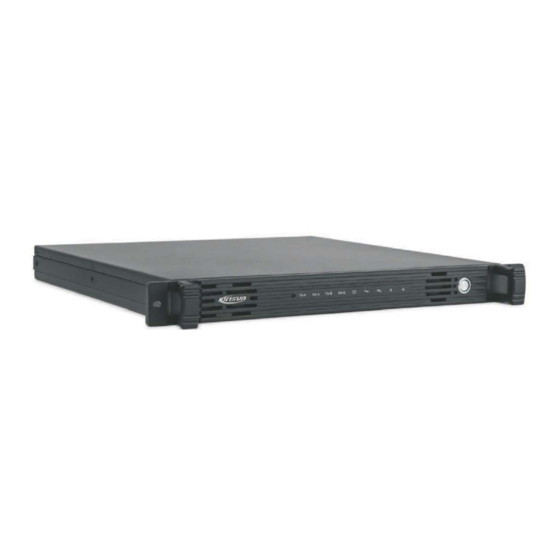
Page 8: Overview
2 Overview - 3 -... - Page 9 Part Name Handle Indicator Power Switch Ground Interface 100-240V AC Inteface 13.6V DC Interace RX Signal Interface ACCY Interface Ethernet Interface GPS Interface TX Signal Inteface - 4 -...
-
Page 10: Power Switch
Power Switch Press this button to power on/off the repeater. ACCY Interface - 5 -... - Page 11 2.2.1 PIN Description Description PIN1 DC 13.6V Output PIN2 Ground Cable PIN3 Null PIN4 Null PIN5 Null PIN6 Null External PTT Signal input, High level active .when connected with Pin20, PIN7 enter transmission mode used for testing and bridge connection; PIN8 SPEAKER- PIN9...
- Page 12 PIN16 Null PIN17 Ground Cable PIN18 External Analogue Audio Input PIN19 Ground Cable PIN20 High level electrical signal output PIN21 Squelch is on when it is connected to PIN20 and it is used for testing PIN22 Null PIN23 Null PIN24 PTT output;...
-
Page 13: Panel Led Indicator
Connect PIN10 and PIN20 of ACCY interface. The repeater changes the IP address and gateway address to the IP on the label, but the data of them are not changed. After re-boot, the configured IP address and gateway address will be recovered. 2.3 Panel LED Indicator Indicator Description... -
Page 14: Basic Operation
Indicator Description Power Indicator 3 Basic Operation 3.1 Power on /off Repeater When the repeater is off, press the power switch glows, to power it on. When the indicator the system starts to operate, and the indicator will indicate the current work mode. Press the power switch to power off the repeater when it is on. -
Page 15: Ip Interface
dealers. One analogue channel or digital/analogue adaptive channel can edit one group of CTCSS/CDCSS codec list, and when CTCSS/CDCSS is received on this channel, the repeater will transmit the correspondent CTCSS/CDCSS codec list. 3.3 IP Interface Default IP address: 192.168.1.100. You can upgrade software, configure the programming parameters and perform extended development through this interface. - Page 16 software trying to connect to the same repeater, it shows busy network status on the second software, meanwhile, the connection button will pop up automatically, and you need to click it for re-connection. 3.5.1 Menu New: creates new channel information. The repeater creates new channel information configuration file and one analogue channel by default with default parameters.
- Page 17 Group Call Hang Time: during group call on the terminal, if no PTT button is pressed on any terminals, the repeater will keep call hang time and does not accept signals of other group. If there is any one of the members press PTT button during the call hang time, the hang time will be counted again.
- Page 18 • Internet Settings Local IP:repeater IP address, such as 192.168.1.100. Subnet Mask: the repeater subnet mask in local area network, such as 255.255.255.0. Gateway: the repeater gateway in the local area network, such as 192.168.1.1. DNS:configure the domain name server or set it as 0.0.0.0. Networking Modes: supports three modes including: no network, as server or as slave device.
- Page 19 Message Delay Setting: the delay setting is used to prevent network latency. The user can set the delay time based on the network status. Value range: 60 milliseconds to 960 milliseconds; step value is 60 milliseconds. • Temperature Control Fan Control Mode: the fan can be turned on constantly or turned on automatically according to power amplification temperature.
- Page 20 CTCSS Frequency: when the CTCSS squelch mode is selected, you need to select one CTCSS frequency value, otherwise the call between two parties is not possible. Value range: 0~254.1Hz; step value is 0.1 Hz; default value: 67 Hz. CDCSS: if the squelch type is CDCSS or –CDCSS, you have to select one CDCSS value, otherwise the call between two parties is impossible.
-
Page 21: Ip Connect
XX”. Upgrade: you can download each function module from PC to repeater and configure with main parameters. Select the path for upgrade package before upgrade. 3.6 IP Connect* An IP connected system can be composed of multiple repeaters through network. This system includes one master device and multiple slave devices (32 members max.). -
Page 22: Parameters
B. Transmission Failure Check if the frequency configuration between the portable and repeater is the same and whether their modes are matched. Parameters , Frequency Range: 136-174MHz, 400-470MHz AC: 100-240V@2.5A 50/60 Hz DC : 10.8-15.6V@15A DC Insurance: 13.6V15A AC Insurance: 2.5A 250VAC, 5x20mm Insurance Type: HRC ceramic, Time lag (T) Supplied Power: 200W TX Power: 40W(UHF) / 45W(VHF) - Page 23 RF Energy Exposure Compliance Your radio is designed and tested to comply with a number of national and international standards and guidelines (listed below) regarding human exposure to radio frequency electromagnetic energy. This radio complies wi th the FCC RF exposure limits for occupational or controlled RF exposure environment and is authorized by the FCC for occupational use only.
- Page 24 Operation is subject to the following two conditions: 1. This device may not cause harmful interference, and 2. This device must accept any interference received, including interference that may cause undesired operation. Note:” Changes or modifications to this unit not expressly approved by the party responsible for compliance could void the user’s authority to operate the equipment.”...
- Page 25 - 18 -...
Need help?
Do you have a question about the DR600 and is the answer not in the manual?
Questions and answers