
Related Manuals for RKI Instruments SDM-03


Summary of Contents for RKI Instruments SDM-03
- Page 1 SDM-03 Docking Station Standalone Configuration Operator’s Manual Part Number: 71-0359 Revision: D Released: 12/2/19 www.rkiins trume nts .c o m...
- Page 2 Warranty RKI Instruments, Inc. warrants gas alarm equipment sold by us to be free from defects in materials and workmanship, and performance for a period of one year from date of shipment from RKI Instruments, Inc. Any parts found defective within that period will be repaired or replaced, at our option, free of charge.
-
Page 3: Table Of Contents
Bump Test & Calibration Parameters ....... . .24 Turning on the SDM-03 with an Instrument ......26 Setting the Bump Test Parameters . - Page 4 Available Memory in the SDM-03 ........48...
-
Page 5: Chapter 1: Introduction
For instructions to use the SDM-03 with the PC Controller Program, see the SDM-03 Docking Station PC Controlled Configuration Operator’s Manual. The purpose of this manual is to explain how to set up and use the SDM-03 in Standalone configuration. It also explains how to use the Single Module Data Viewer Program. You will learn how to: •... -
Page 6: System Requirements
CAUTION: The operator of this instrument is advised that if the equipment is used in a manner not specified in this manual, the protection provided by the equipment may be impaired. System Requirements To use the Single Module Data Viewer Software, your personal computer must meet the following requirements: ®... -
Page 7: Specifications
• One 3 Foot Long Tube for GAS Fitting • 10 Foot Long 3/16 Inch Tube for GAS manifolding • 2 T-Fittings • Check Valve • USB Cable, Type A to Type B Not sent with SDM-03. Download from www.rkiinstruments.com/sdm03. Chapter 1: Introduction • 7... -
Page 8: About This Manual
• Use only polyurethane sample tubing with the SDM-03. Consult RKI Instruments, Inc. for other materials. • Do not subject the SDM-03 to infrared or intense light. This may cause communication errors. • Do not expose the SDM-03 to water. -
Page 9: Chapter 2: Description
Chapter 2: Description Overview This section describes the SDM-03 docking station. It is designed to be used on a table top and consists of the AC adapter, Type A to Type B USB cable, air filter, check valve, 2 plastic T- fittings, sample tubing, instrument cradle, back panel, control panel, status LEDs, and 2 USB ports. -
Page 10: Usb Cable
Figure 3: USB Cable Air Filter A cylindrical particle filter with a short length of tubing is supplied with the SDM-03 for installation to the AIR fitting on the back panel. The filter keeps particulate contamination out of the docking station. - Page 11 Check Valve A check valve is included with the SDM-03. It is intended for use on the exhaust fitting when manifolding multiple docking stations together. See “Assembling a Manifold for Multiple SDM-03s” on page 18 for manifolding instructions.
-
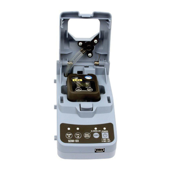
Page 12: Instrument Cradle
Instrument Cradle The instrument cradle is a recessed area on the top of the SDM-03 that is designed to accept the 03 Series. Insert the 03 Series in the instrument cradle when you perform a bump test or calibration. A spring-loaded cover latches into place to secure the 03 Series. A sample port in the cover matches up with the 03 Series’... -
Page 13: Back Panel
Two sample fittings are located on the back of the SDM-03. The AIR fitting is in the upper left corner and draws air into the SDM-03. The GAS fitting is to the right of the AIR fitting and is used to connect the SDM-03 to a calibration gas cylinder. Both fittings accept 3/16 inch ID tubing. -
Page 14: Control Panel
BUMP CAL. COPY ENTER 1SEC ON SDM-03 3SEC OFF Control Buttons Figure 9: Control Panel Five control buttons are located on the control panel. From left to right they are BUMP , CAL , EDIT ENTER, COPY, and POWER. The BUMP , CAL , and COPY control buttons each have an LED above them that indicates the status of the function controlled by that button. - Page 15 Table 2: Control Button Functions Control Control Button Function(s) Control Button LED Function(s) Button CAL Indicates status of a calibration in • Initiates a calibration progress • Cancels a calibration • Clears data from docking station memory (when used with COPY button) •...
-
Page 16: Front Panel
USB flash drive. This USB port is for use only in the Standalone configuration of the SDM-03. Figure 10: Front Panel NOTE: The SDM-03 does not support connection of a computer to the front USB port, only a USB flash drive. 16 • Chapter 2: Description... -
Page 17: Chapter 3: Preparing To Use The Sdm-03
Perform the following to complete the hardware assembly: 1. Place the SDM-03 on a convenient table top near an AC wall socket in a well ventilated area. A location near a window that can be opened is best so that the exhaust can be routed to the window. -
Page 18: Assembling A Manifold For Multiple Sdm-03S
6. Install the 3 foot long 3/16 inch ID tube that is included with the SDM-03 on the GAS fitting. GAS tubing from multiple units can be daisy chained together in a manifold for more convenient operation. See "Assembling a Manifold for Multiple SDM-03s" below for manifold requirements and for instructions. - Page 19 Figure 11: Exhaust Tubing Connections Chapter 3: Preparing to Use the SDM-03 • 19...
- Page 20 GP-03s, a 4-unit manifold for OX-03s, and a 3-unit manifold for CO-03s). See the next section for instructions to make multiple GAS manifolds. 1. Cut a 3-4” piece of 3/16 inch tubing for each GAS fitting on every SDM-03 except the last one.
- Page 21 Figure 12: Gas Manifold Connections, 1 Manifold for All 10 Stations Chapter 3: Preparing to Use the SDM-03 • 21...
- Page 22 4-unit manifold for OX-03s, and a 3-unit manifold for CO-03s). For each manifold bank, do the following: 1. Cut a 3-4” piece of 3/16 inch tubing for each GAS fitting on every SDM-03 except the last one. 2. Connect the tubing to the GAS fitting on every SDM-03 except the last one.
- Page 23 Figure 13: Gas Manifold Connections, Multiple Manifolds for Multiple Versions Chapter 3: Preparing to Use the SDM-03 • 23...
-
Page 24: Setting The Operational Parameters In Edit Mode
The bump test and calibration parameters are saved in the SDM-03’s memory. If a parameter is changed with one particular instrument installed in the SDM-03, the change will be in effect for the bump test or calibration of any subsequent instruments until the parameter is changed again. - Page 25 The air sample time can be set separately for bump testing and calibration. It is the length of time that the SDM-03 will draw air through the AIR fitting on the back of the docking station. Air is drawn during a bump test or calibration before an air adjust operation and to purge calibration gas from the system after calibration gas has been drawn through the GAS fitting on the back of the docking station.
-
Page 26: Turning On The Sdm-03 With An Instrument
Do the following to turn on the SDM-03 and establish a connection with an instrument: 1. Confirm that the AC adapter is connected to the SDM-03 and to an AC wall socket. 2. Press and hold the SDM-03’s POWER button. The LEDs will turn amber. - Page 27 C.LIMIT The alarm LED and buzzer will pulse several times. The instrument will then connect to the SDM-03 and display the home screen shown above in step 7. • When Cal. Limit Display is set to On, if the unit is due for calibration and if Cal.
-
Page 28: Setting The Bump Test Parameters
See “Bump Test & Calibration Parameters” on page 24 for a description of the bump test parameters. Do the following to set the bump test parameters. 1. Turn on the SDM-03 with an instrument and establish a connection between them as described above in "Turning on the SDM-03 with an Instrument". The instrument will display the home screen. - Page 29 6. Use the BUMP and CAL buttons to set the parameter to the desired value, then press and release the EDIT ENTER button. The “E” to the right of parameter name will disappear. 7. Repeat step 5 - step 6 to set any other parameters. Chapter 3: Preparing to Use the SDM-03 • 29...
-
Page 30: Setting The Calibration Parameters
See “Bump Test & Calibration Parameters” on page 24 for a description of the calibration parameters. Do the following to set the calibration parameters. 1. Turn on the SDM-03 with an instrument and establish a connection between them as described above in "Turning on the SDM-03 with an Instrument". The instrument will display the home screen. - Page 31 8. When you are done setting the parameters, use the BUMP button to scroll past the GAS--IN parameter screen. The screen will indicate that the parameter changes have been saved. SAVING 9. The instrument will return to the home screen. Chapter 3: Preparing to Use the SDM-03 • 31...
-
Page 32: Connecting Calibration Gas
HS-03 25.0 ppm H To connect calibration gas to the SDM-03, do the following: 1. If the area around the docking station is not considered a fresh air area (an area free of combustible and toxic gases and of normal oxygen content, 20.9%) install a tube not... -
Page 33: Installing The Single Module Data Viewer Software
Windows files on your computer than those in the Installation CD. If this happens, the installation software will ask you if you want to keep these newer files. Click Yes to do so. 16.Follow the on-screen instructions to complete software installation. Chapter 3: Preparing to Use the SDM-03 • 33... -
Page 34: Chapter 4: Operation
Program. Bump Testing an 03 Series When a bump test is performed, the SDM-03 performs a fresh air adjustment on an 03 Series and then applies calibration gas to the instrument. The docking station then analyzes the response results based on criteria defined by the bump test check tolerance parameter and determines if the instrument passed the bump test. - Page 35 CHANGE BATT The instrument will not connect to the SDM-03 until the batteries are replaced as described in the GP-03 or OX-03/CO-03/HS-03 Operator’s Manual and the instrument is turned back on. 9. There are two exceptions to the sequence described in step 7 above. See the 03 Series User Setup Program Operator’s Manual for a description of the Cal.
- Page 36 “Setting the Bump Test Parameters” on page 28. 11.Verify that the appropriate calibration gas cylinder is connected to the GAS fitting on the back of the SDM-03. See “Connecting Calibration Gas” on page 32 for calibration gas connection procedures. 12.Press and hold the BUMP button until the BUMP LED turns on (about one second) then release it.
- Page 37 To perform a calibration, press and release the CAL button. • 14.The SDM-03 will begin the bump test by applying fresh air to the instrument for the time defined by the AIR--IN bump test parameter. 15.The SDM-03 will perform a fresh air adjustment on the instrument.
- Page 38 “Using the Single Module Data Viewer Program” on page 53 for a description of calibration results. 18.The SDM-03 will then purge the system with fresh air for the time defined by the AIR--IN bump test parameter. 19.After the fresh air purge is complete, the 03 Series screen will alternate between the gas reading and the bump test or bump test and calibration result.
- Page 39 %LEL BUMP BUMP Figure 15: Screen Indication for Passed Bump Test %LEL BUMP BUMP Figure 16: Screen Indication for Failed Bump Test, CAL OFF %LEL Figure 17: Screen Indication for Failed Bump Test and Passed Automatic Calibration %LEL Figure 18: Screen Indication for Failed Bump Test and Failed Calibration Chapter 4: Operation •...
- Page 40 BUMP or BUMP and CAL LEDs will automatically be cleared. 21.The results of the bump test or bump test and calibration will be stored in the SDM-03’s memory and will be available to copy to a USB flash drive. See “Copying Calibration and Bump Test Records to a USB Flash Drive”...
-
Page 41: Calibrating An 03 Series
GP-03 but the instructions apply to all versions of the 03 Series. To perform a calibration on an 03 Series: 1. Confirm that the AC adapter is connected to the SDM-03 and to an AC wall socket. 2. Press and hold the SDM-03’s POWER button. The LEDs will turn amber. - Page 42 CHANGE BATT The instrument will not connect to the SDM-03 until the batteries are replaced as described in the GP-03 or OX-03/CO-03/HS-03 Operator’s Manual and the instrument is turned back on. 9. There are two exceptions to the sequence described in step 7 above. See the 03 Series User Setup Program Operator’s Manual for a description of the Cal.
- Page 43 SDM-03 and display the home screen shown above in step 7. 10.Verify that the appropriate calibration gas cylinder is connected to the GAS fitting on the back of the SDM-03. See “Connecting Calibration Gas” on page 32 for calibration gas connection procedures.
- Page 44 15.The SDM-03 will apply calibration gas to the instrument for the time defined by the GAS- -IN calibration parameter. %LEL 16.The SDM-03 will then purge the system with fresh air for the time defined by the AIR--IN calibration parameter. 44 • Chapter 4: Operation...
- Page 45 If the calibration was successful, the instrument will shut off after 15 seconds. If the calibration failed, the instrument will shut off after 10 minutes. If buttons are pressed before the SDM-03 turns off the instrument, it will automatically turn it off 10 minutes after the last button push.
- Page 46 19.The results of the calibration will be stored in the SDM-03’s memory and will be available to copy to a USB flash drive. See “Copying Calibration and Bump Test Records to a USB Flash Drive” on page 49 for instructions to copy the saved bump test and calibration records to a USB flash drive.
-
Page 47: Troubleshooting
Troubleshooting NOTE: This troubleshooting guide describes SDM-03 problems only. See the GP-03 or OX-03/CO-03/HS-03 Operator’s Manual for problems you may encounter with the instrument. Table 5: Troubleshooting the SDM-03 Symptoms Probable Causes Recommended Action Fresh air adjustment • The SDM-03 is not in a fresh 1. -
Page 48: Calibration And Bump Test Records
Calibration and Bump Test Records The SDM-03 saves a record of each bump test and calibration performed. It is capable of saving up to 200 such records. When an SDM-03’s memory becomes full, the oldest record is overwritten when a new record is saved. The records saved in the SDM-03’s memory can be saved to a USB flash drive using the USB port on the front. -
Page 49: Copying Calibration And Bump Test Records
(see "Available Memory in the SDM-03" above). 5. Install a USB flash drive into the USB port on the front of the SDM-03. The SDM-03 will take a few seconds to determine how much memory is available in the flash drive. -
Page 50: Clearing The Sdm-03'S Memory
The file name will begin with “SDM-03” and the remainder of the file name will depend on the serial number of the SDM-03 used and the date of the most recent bump test or calibration performed on the SDM-03. So it is possible to have multiple files in the DAT folder from the SDM-03. - Page 51 CAUTION: If performing bump tests or calibrations and copying an SDM-03’s memory to a flash drive multiple times during the same day and the SDM-03’s memory is cleared, transfer the calibration/bump test record files from the flash drive to a computer hard drive or some other memory device before performing another copy operation to avoid loss of data.
-
Page 52: Chapter 5: Single Module Data Viewer Program
The Single Module Data Viewer Program is used to view, organize, and print bump test and calibration records that were created by the SDM-03 while used in the standalone configuration. It can also be used to export these records from its database for use in other programs. -
Page 53: Data Viewing Window
In the example above, the data is organized by date. You can do the following in the data viewing window: • Import files into the database that were created by an SDM-03 Chapter 5: Single Module Data Viewer Program • 53... -
Page 54: Importing Files Into The Database
Print a bump test or calibration report that includes the results and all gas readings. Importing Files Into the Database The files generated by the SDM-03 are structured to be imported into the Single Module Data Viewer Program database. To import data files into the database, do the following: 1. -
Page 55: Organizing The Data
Organizing the Data When viewing the data, it can be organized in two ways: 1. Base View Format In base view format, neither of the Serial No, Station ID, or User ID selection boxes in the lower left of the window are selected and the Base box appears next to these selection boxes with two radio buttons. -
Page 56: Viewing The Data
2. ID View Format In ID view format, the data can be organized by one or more of the following items depending on which selection box or boxes in the lower left corner of the data viewing window are selected: •... - Page 57 2. When an item no longer has a (+) or (-) symbol next to it, single click it and the contents of the item will be shown on the right side of the window. 3. If you are viewing data in base view format with the data organized by type, expand the item, bump test or calibration, you wish to view.
- Page 58 If you organize the data by date, then folders organized by year/month appear in the left side of the window. Expand the folder you want to see and click on the calibration or bump test folder. The calibration or bump test files will appear in the upper right side of the window.
- Page 59 If you are viewing data in ID view format, expand the folders in the left side of the window until the bump test or calibration folder you wish to view is visible. Expand the folder by clicking the (+) symbol next to it. Folders organized by year/month will be listed below the calibration or bump test folder.
- Page 60 5. To view the file contents, click on the file in the upper right part of the data view window that you wish to view. The contents in the file will appear in the lower right part of the window. The contents include the instrument’s serial number, station ID, user ID, bump test or calibration time, test gas, and gas readings during the operation.
-
Page 61: Deleting Data
Save To File button has a floppy disk icon in it. A “Save As” dialog box will appear for you to specify the filename, file location, and file type. Select the Text files (*.csv) choice to save the information as a comma separated value file that may be opened with a spreadsheet program such as Microsoft Excel. -
Page 62: Changing The Password
Changing the Password The factory password is “ABCDE” and is case sensitive. You can change the password in the data view window. To change the password perform the following: 1. Right click in the upper right or upper left part of the data view window. A window will appear that says “Delete(D) Change Password(C)”. -
Page 63: Exiting The Program
6. Click OK to complete the password update. Exiting the Program To exit the Single Module Data Viewer Program, do the following: 1. Click the Exit button in the upper right corner of the data view window. A confirmation window will appear. 2. -
Page 64: Chapter 6: Spare Parts List
49-2058RK-04 4-port AC adapter 71-0359 Operator’s Manual, SDM-03 Docking Station Standalone Configuration (this document) 71-0360 Operator’s Manual, SDM-03 Docking Station PC Controller Configuration 71-8007RK Product CD for SDM-GX Series, includes Single Module Data Viewer Program 81-0012RK-01 Calibration cylinder, 50% LEL CH... - Page 65 Table 7: Spare Parts List Part Number Description 81-0078RK-01 Calibration cylinder, 100% nitrogen, 34 liter steel 81-0078RK-03 Calibration cylinder, 100% nitrogen, 103 liter 81-0151RK-02 Calibration cylinder, 25 ppm H S in nitrogen, 58 liter 81-0151RK-04 Calibration cylinder, 25 ppm H S in nitrogen, 34 liter aluminum 81-1054RK Demand flow regulator, for 34 liter aluminum, 58 liter, and 103 liter...
Need help?
Do you have a question about the SDM-03 and is the answer not in the manual?
Questions and answers