
Subscribe to Our Youtube Channel
Related Manuals for RKI Instruments SDM-3R


Summary of Contents for RKI Instruments SDM-3R
- Page 1 SDM-3R Docking Station PC Controlled Configuration Operator’s Manual Part Number: 71-0488 Revision: P1 Released: 5/24/19 www.rkiinstruments.com...
- Page 2 Warranty RKI Instruments, Inc. warrants gas alarm equipment sold by us to be free from defects in materials and workmanship, and performance for a period of one year from date of shipment from RKI Instruments, Inc. Any parts found defective within that period will be repaired or replaced, at our option, free of charge.
-
Page 3: Table Of Contents
Wall Mounting the SDM-3R, Optional ........ - Page 4 GX-3R (Pro), EAGLE 2, and Other GX Type Instrument Connection ....41 Overview of the SDM-3R PC Controller Program ......41 PC Program Functions .
- Page 5 Charging a GX-3R (Pro) in an SDM-3R ........
-
Page 6: Chapter 1: Introduction
Docking Station Standalone Configuration Operator’s Manual. The purpose of this manual is to explain how to set up and use the SDM-3R in PC Controlled configuration. It also explains how to use the SDM-3R Docking Station PC Controller Program. You will learn how to: •... -
Page 7: System Requirements
System Requirements To use the SDM-3R Docking Station PC Controller Software, your personal computer must meet the following requirements: ® ® ® • Operating Systems: Windows 7, Windows 8, Windows ® ® • Processor: IBM compatible PC running Pentium 2 processor or equivalent minimum •... -
Page 8: Specifications
• USB Cable, Type A to Type B • Ethernet Cable • Single-Station AC Adapter • USB Drive Available Accessories • Multi-Station AC Adapter • Connection Brackets • Wall Mounting Brackets * Not sent with SDM-3R. Download from www.rkiinstruments.com/sdm3r. 8 • Chapter 1: Introduction... -
Page 9: Chapter 2: Description
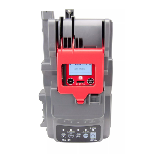
Instrument Cradle The instrument cradle is a recessed area in the middle of the SDM-3R that is designed to accept the GX-3R or the GX-3R Pro. The yellow lever in the cradle must be up for GX-3R operation and down for GX-3R Pro operation. -
Page 10: Control Buttons And Leds
Control Buttons and LEDs The SDM-3R’s control buttons have no function during PC Controlled operation but the LEDs above the buttons still indicate that operations are in process and indicate the pass/fail status for those processes. Control Button LEDs CHARGE... -
Page 11: Cylinder Connections (Side Panels)
Cylinder Connections (Side Panels) Four gas fittings are located on the left side of the SDM-3R. Three are for gas cylinders and one is for the particle filter or a zero air cylinder. The left to right order is: GAS 3, GAS 2, GAS 1, AIR. All four fittings accept 3/16 inch ID tubing. -
Page 12: Power And Network Connections (Back Panel)
USB PC Connector A type B USB connection allows for the SDM-3R to be connected to a PC using a Type A to Type B USB cable. Connection to a PC is necessary for setting up the LAN function and for using the SDM- 3R in its PC controlled configuration. -
Page 13: Standard Accessories
SDM-3R’s power jack. A screw included with the SDM-3R allows you to secure the plug to the SDM-3R’s jack if desired. The AC adapter is rated 100 - 240 VAC input, 5.99 VDC 2 A output. -
Page 14: Usb Cable
USB Cable A Type A to Type B USB cable is used to connect the SDM-3R to a PC which is required for using the SDM-3R in the PC Controlled configuration. If you have a multi-station system, the USB cable only needs to be plugged into the master (leftmost) station. -
Page 15: Wall Mounting Brackets
Wall Mounting Brackets The SDM-3R can be mounted to the wall, if desired, using 2 mounting brackets. See “Wall Mounting the SDM-3R, Optional” on page 18 for a description of how many wall mounting brackets are needed depending on how many SDM-3Rs are in your system. -
Page 16: Chapter 3: Hardware Setup
Chapter 3: Hardware Setup Overview Setting up the SDM-3R for use in its PC Controlled Mode includes: connecting multiple SDM-3Rs together (optional), connecting the AC adapter, air filter, and exhaust tubing, wall mounting the station (optional), and connecting calibration gas. Instructions to complete each of these tasks is in this section. - Page 17 (Optional) Use the metal connection brackets and screws (sold separately) to secure the two connection points on the bottom of the SDM-3R to each other. Figure 9: Connecting SDM-3Rs Together, Back Panel...
-
Page 18: Hardware Assembly
Connect the provided USB cord from the type B USB port on the back of the SDM-3R to an available USB port on your computer or to a USB hub that is connected to your computer. - Page 19 Total # of wall mounting # of SDM-3Rs brackets necessary 1 SDM-3R 2 wall mounting brackets 2-4 SDM-3Rs 4 wall mounting brackets 5-7 SDM-3Rs 6 wall mounting brackets Figure 10: Wall Mounting 1-7 SDM-3Rs Chapter 3: Hardware Setup • 19...
- Page 20 They have a short section and a long section. The short section has a smaller hole than the long section. Screw the short section into the SDM-3R making sure that the long section goes away from the station and is flush with the back of the SDM-3R.
-
Page 21: Installing The Cylinder Holder, Optional
Installing the Cylinder Holder, Optional Choose a location for the calibration cylinders that is close to the SDM-3R. 4 pads with adhesive on each side are included with each cylinder holder. -
Page 22: Connecting Calibration Gas
A demand flow regulator and a cylinder of zero emissions air A fresh air area GAS 1, Recommended Gas RKI Instruments, Inc. recommends using one of the following for the GAS 1 fitting: A 4-gas mix (LEL/O /CO/H S) for GX-3R (Pro)s that have an H... - Page 23 If testing different GX-3R (Pro) combinations at once requires more than 3 cylinders, you can assign channels to CHG 3 in the SDM-3R’s Configuration Menu and the SDM will prompt you to change cylinders during a bump test or calibration.
- Page 24 Install the demand flow regulator(s) on the calibration gas cylinder(s). NOTE: Do not connect pressurized gas directly to the SDM-3R. Be sure to install a demand flow regulator on the cylinder before connecting it to the SDM-3R. Connect the demand flow regulator to the appropriate inlet fitting using 3/16 inch ID sample tubing.
-
Page 25: Chapter 4: Program Setup
Chapter 4: Program Setup Overview This chapter describes how to install the SDM-3R Docking Station PC Controller Program, set up cylinders in the Cylinders Window, and set up the PC Program operation in the Config Window. See “Chapter 5: Operation” on page 41 for a description of program operation. - Page 26 15. Turn on the docking station by flipping the power switch to the ON position. 16. The first time an SDM-3R is turned on after being connected to the computer, the SDM-3R needs some time to be recognized by the computer. The status bar will indicate that the drivers are being configured and will alert you when the SDM-3R is ready to use.
-
Page 27: Setting Up Cylinders
Selecting a Cylinder from the Predefined List The Cylinders Window comes with several predefined cylinders that you can choose from. Click Start on the Windows Icon Tray, then select Programs/SDM-3R. You may also double click the shortcut created on your desktop. - Page 28 Click the Name field, click the drop down menu icon, and select a cylinder. Figure 16: Predefined Cylinder List When you press the Tab key on your keyboard or click in another field, the Part No. field automatically populates. To edit the part number, double click in the Part No field and type in a part number.
-
Page 29: Defining New Cylinders
Defining New Cylinders If your GX-3R (Pro) configuration requires the use of a cylinder that is not in the predefined list, you can add that cylinder by either typing in the information for the cylinder or by editing the information for an existing cylinder. -
Page 30: Defining Pc Program Operation
PC Program operation. Changing anything in the Parameter Tab of the Config Window does not change any settings in the SDM-3R and, therefore, does not affect Standalone Mode operation. While in the main program window, click the Config button. - Page 31 Click OK and then click Yes in the window that comes up to save the settings and return to the Main Window. Email The PC Program can be configured to send emails out whenever an instrument is bump tested, calibrated, or alarm checked. An example of an alarm check email is shown below. Click Email.
- Page 32 Select Send Email. If you only want an email to send when a test fails and don’t want an email to send when a test passes, select Send only on FAIL. Type in the domain name and IP address of your mail server. This information will likely need to be obtained from your IT department.
- Page 33 Instrument Information Section Change Parameter Selected (factory setting): The Edit function is active, allowing you to change parameters in connected GX-3R (Pro)s. See pg. 78 for information about instrument parameters. Deselected: The Edit function is not active and GX-3R (Pro) parameters cannot be edited. Auto Power OFF Time This is the length of time that will pass after the last operation is finished before the program will automatically shut off the GX-3R (Pro).
- Page 34 Your SDM-3Rs should all appear on the screen in numerical order. The program will remember each SDM-3R’s number. Once the display order is set, if fewer than all of the docking stations are turned on, the stations will still appear in numerical order on the main window, but the stations which are off will not be shown.
- Page 35 Bump Test Section If neither Manual Bump Test nor Auto Bump Test is selected, you will not be able to perform a bump test. Select the box for the desired operation. Manual Bump Test Selected (factory setting): A manual bump test can be performed by selecting an instrument or instruments in the main program window and clicking Bump Test in the lower right corner of the window.
- Page 36 Table 2: Example Fast Bump Scenarios Gas Reading After 10 Seconds of Gas Application and a 10 Second Outcome Wait Period 80% LEL (+60% of 50% LEL) • Bump test fails • Next step depends on AUTO CAL setting Standard GAS/All GAS Standard GAS selected (factory setting): Only the standard sensors (catalytic LEL, O , CO, and H will be bump tested during an automatic bump test.
-
Page 37: Database Tab
Database Tab The Database tab allows you to: • view or change the database location • create a brand new database • import data from another database • export saved data Figure 21: Config Window Database Tab Changing the Database Location While in the main program window, click the Config button. - Page 38 Create button, or you can navigate to another network computer’s .mdb file. The default location for the .mdb file is C:\Program Data\SDM-3R\SDMLog.mdb. Hidden folders must be visible on the computer in order to locate the .mdb file.
-
Page 39: Password Tab
If you want a GX-3R (Pro)’s information removed from the database after export, be sure the instrument is not currently connected to the PC Program, then select Remove. Click Export. Select where you would like to save the file, and click Save. The program will indicate that it is exporting the data and will confirm that it has finished. - Page 40 While in the Configuration Window, click on the Password tab. For each password, enter the new password in the top box and confirm it in the bottom. Make any other desired changes in the Parameter and Database tabs. Click OK and then Yes to confirm the changes and return to the Main Window. 40 •...
-
Page 41: Chapter 5: Operation
It also contains troubleshooting information and instructions for instrument charging. NOTE: When the SDM-3R is connected to the PC Program, the date and time of the docking station are automatically updated to the current date and time on the PC Program’s screen. -
Page 42: Main Program Window
Print Save Export Message Area SDM-3R/GX-3R (Pro) Display Area Figure 23: Parts of the Main Program Window Control Buttons The Cylinders, Config, Logs, and Exit control buttons are located along the top right of the window. -
Page 43: Connecting Gx-3R (Pro)S
Confirm that the AC adapter is connected to the SDM-3R and to an AC wall socket. Connect the Type A to Type B USB cable to the SDM-3R and to an available USB port on your computer or to a USB hub that is connected to your computer. - Page 44 Install the GX-3R (Pro) into the SDM-3R’s instrument cradle. Be sure the yellow lever is up for a GX-3R and down for a GX-3R (Pro). 10 . Close the red door. The GX-3R (Pro) will automatically turn on and connect to the SDM-3R. %LEL 25.0...
- Page 45 15. If a GX-3R (Pro) is due for calibration within the next 10 days, the docking station number and instrument serial number will be highlighted in orange. 16. If a GX-3R (Pro)’s basic parameters could not be downloaded properly, a red triangle will appear over the GX-3R (Pro)/SDM-3R icon. Chapter 5: Operation • 45...
-
Page 46: Icon View Vs. Details View
Icon View allows you to view connected GX-3R (Pro)s and previously connected GX-3R (Pro)s in an icon configuration. Connected GX-3R (Pro)s are shown as a GX-3R (Pro) inserted in an SDM-3R icon. Previously connected GX-3R (Pro)s are shown as GX-3R (Pro) icons. Right clicking a GX-3R (Pro) causes the Instrument Function Menu to appear. - Page 47 Details View Details View allows you to view connected GX-3R (Pro)s and previously connected GX-3R (Pro)s in a table format. Scrolling to the right in Details View allows you to view existing GX-3R (Pro) parameters. For a description of these parameters and instructions to change them, see “Chapter 7: Changing GX-3R (Pro) Parameters”...
-
Page 48: Printing And Exporting An Instrument List From The Main Window
Printing and Exporting an Instrument List from the Main Program Window You can print, save, or copy the instrument list to the clipboard in the main program window. You can only print the list if it is viewed in Details format. The list cannot be printed when viewed in Icon format. -
Page 49: Automatic Procedures
Performing a Bump Test Bump test parameters are defined in the Config Window. See pg. 30 for a description of the bump test configuration setup. Establish a connection between the SDM-3R, GX-3R (Pro) and the PC Program as described on pg. 43. NOTE: The instrument cradle’s yellow lever needs to be up for GX-3Rs and down for GX-... - Page 50 Verify that the appropriate calibration gas cylinders are connected to the gas fittings on the left side of the SDM-3R. See pg. 22 for calibration gas cylinder options and calibration gas connection procedures. Highlight the GX-3R (Pro)(s) you wish to bump test.
- Page 51 You are asked to confirm which gases will use the GAS 1 fitting for the bump test. Each gas will only appear once, even if multiple instruments with the same target gas are being bump tested. The gas concentration shown next to each gas name is the auto calibration value for that gas.
- Page 52 Use the selection box below each inlet assignment to select or deselect that gas for bump testing. NOTE: Your SDM-3R will only have as many gas inlet choices as it has solenoid valves. For example, an SDM-3R with only one solenoid valve will only have GAS1 as a choice. 10. Click OK.
- Page 53 14. The SDM-3R then applies calibration gas in the order of the gas inlets for the length of time defined in Gas Exposure Time in the Config Window. If Fast Bump is selected in the Config window, gas is applied for 10 seconds, then the pump stops and the station goes through a 10 second stabilization period.
- Page 54 15. The SDM-3R analyzes the results after the end of each gas application. If the bump test fails and Auto Cal If Bump Fails is selected in the Config window, the gas keeps flowing and a calibration automatically begins. Figure 33: Calibration Gas Flowing 16.
- Page 55 18. A pop-up window shows the bump test results. If the bump test failed and Auto Cal If Bump Fails was selected in the Config window, the screen shows calibration results, too. Figure 35: Bump Test/Calibration Result Screen 19. Click OK to return to the main program window or double click an instrument information line to view the bump test and/or calibration results in the Logs window.
-
Page 56: Performing A Calibration
Verify that all of the calibration parameters are set correctly. See pg. 30 for instructions. Verify that the appropriate calibration gas cylinders are connected to the gas fittings on the left side of the SDM-3R. See pg. 22 for calibration gas cylinder options and calibration gas connection procedures. - Page 57 You are asked to confirm which gases will use the GAS 1 fitting for the calibration. Each gas only appears once, even if multiple instruments with the same target gas are being calibrated. The gas concentration shown next to each gas name is the auto calibration value for that gas. If it does not match the gas concentration listed on the cylinder, change the auto calibration value for the instrument(s) associated with that gas.
- Page 58 Use the selection box below each inlet assignment to select or deselect that gas for bump testing. NOTE: Your SDM-3R will only have as many gas inlet choices as it has solenoid valves. For example, an SDM-3R with only one solenoid valve will only have GAS1 as a choice. 10. Click OK.
- Page 59 13. The PC Program performs a zero adjustment and analyzes the results. If any sensors failed the zero adjustment, the calibration for that instrument is aborted. 14. The SDM-3R then applies calibration gas in the order of the gas inlets for 60 seconds per inlet. Chapter 5: Operation • 59...
- Page 60 15. The SDM-3R analyzes the results after the end of each gas application. Figure 40: Calibration Gas Flowing 60 • Chapter 5: Operation...
- Page 61 16. After calibration gas is applied, the docking station purges with fresh air for 15 seconds. Figure 41: Fresh Air Purge Chapter 5: Operation • 61...
- Page 62 17. A pop-up window shows the calibration results. Figure 42: Calibration Result Screen 18. Click OK to return to the main program window or double click an instrument information line to view the calibration results in the Logs window. 19. For all calibration result outcomes, the GX-3R (Pro)(s) are displayed in the main program window in Details View.
-
Page 63: Performing An Alarm Check
3R (Pro). When an alarm check is performed, the PC Program checks the operation of the instrument’s LEDs and buzzer. The PC Program analyzes the alarm check results and determines if the GX-3R (Pro) passed the alarm check. Establish a connection between the SDM-3R, GX-3R (Pro) and the PC Program as described on pg. 43. NOTE: The instrument cradle’s yellow lever needs to be up for GX-3Rs and down for GX-... - Page 64 Click OK to proceed. . The instrument’s LEDs and buzzer are checked. A pop-up window shows the alarm check results. Figure 44: Alarm Check Result Screen Click OK to return to the main program window or double click an instrument information line to view the alarm check results in the Logs window.
-
Page 65: Chapter 6: Changing Sdm-3R Parameters
Open the PC Program. Confirm that the AC adapter is connected to the SDM-3R and to an AC wall socket. Connect the Type A to Type B USB cable to the SDM-3R and to an available USB port on your computer. - Page 66 If the Password parameter in the Bump & Cal 2 Tab of the SDM Window is selected (factory setting is deselected), the program prompts you for a password to enter the SDM Window. Enter the password and click OK. 66 • Chapter 6: Changing SDM-3R Parameters for Standalone Operation...
- Page 67 The SDM Window opens and the Bump & Cal 1 Tab is displayed. Each tab in the SDM Window is described in the sections that follow. Figure 45: Bump & Cal 1 Tab Chapter 6: Changing SDM-3R Parameters for Standalone Operation • 67...
-
Page 68: Bump & Cal 1 Tab
Bump & Cal 1 Tab This section describes the Bump & Cal 1 Tab of the SDM Window. Figure 46: Bump & Cal 1 Tab 68 • Chapter 6: Changing SDM-3R Parameters for Standalone Operation... - Page 69 • Deselected (Off) Auto Bump (for bump only) Selected: A bump test automatically begins whenever a GX-3R (Pro) is connected to SDM-3R, whether the instrument is due for a bump test or not. Deselected (factory setting): A bump test will not automatically begin whenever a GX-3R (Pro) is connected to the SDM-3R.
- Page 70 GAS (for bump and calibration) The gas sample time is the length of time that the SDM-3R draws calibration gas through each of the gas fittings. It can be set from 20 to 120 seconds. The factory setting for bump test is 20 seconds. The factory setting for calibration is 60 seconds.
- Page 71 Selected (factory setting): A GX-3R (Pro) LED and buzzer test is done at the end of the bump test or calibration. The LEDs turn on for a few seconds, the buzzer sounds, and the SDM-3R determines if these actions were completed successfully.
-
Page 72: Bump & Cal 2 Tab
Deselected: A calibration cannot be manually initiated using the SDM-3R’s CAL button. Auto cal if past due (for calibration only) Selected: If the connected GX-3R (Pro) is due for a calibration, the SDM-3R automatically performs a calibration on all channels immediately after the GX-3R (Pro) is connected. - Page 73 Interval: A data download is performed once per interval when a GX-3R (Pro) is connected to the SDM-3R and a USB drive is installed in the USB port on the front of the SDM-3R. If this option is selected, the Data Logger Interval parameter becomes active and needs to be set. The Data Logger Interval parameter is described below.
- Page 74 Turning the password on (factory setting is off) adds password protection to the SDM Window and to the Configuration Menu if the SDM-3R is used in Standalone Mode. The factory set password is 0000 but a user selected password can be entered in the space to the right of the ON selection box.
-
Page 75: Internal Tab
The Internal Tab is used for setting up a LAN connection on a non-DHCP network and does not have any function in the SDM-3R’s PC Controlled Configuration. Instructions for using the Internal Tab can be found in the SDM-3R Standalone Configuration Manual. -
Page 76: Automatic Tab
The Automatic Tab allows you to set up a bump test, calibration, or alarm check to automatically occur at a specific time on the desired day(s). If a GX-3R (Pro) is installed in an SDM-3R at the specified day/time, the SDM-3R will turn the GX-3R (Pro) on, perform the test, then turn the GX-3R (Pro) off. -
Page 77: Exporting An Sdm File
Use the Export File button on the right side of the SDM Window to save a parameter configuration file based on a connected SDM-3R’s parameter settings. The file can then be uploaded at a later time to another SDM-3R to make its parameter settings match the original SDM-3R’s parameter settings or to restore the parameter settings of the original SDM-3R if they have been changed. -
Page 78: Chapter 7: Changing Gx-3R (Pro) Parameters
All of the parameters that can be changed in the Edit function tabs are GX-3R (Pro) parameters only. Any changes made do not affect operation of the SDM-3R or the PC Program. Establish a connection between the SDM-3R, GX-3R (Pro) and the PC Program as described on pg. - Page 79 Table 6: Parameters Parameter Tab Name Applicable Factory Location Available Choices (pg. # of description) Instrument Setting Disp Mode HC Gas List (pg. 84) • GX-3R • • GX-3R Pro Invert Select (pg. 85) • GX-3R Pro • selected deselected •...
- Page 80 Table 6: Parameters Parameter Tab Name Applicable Factory Location Available Choices (pg. # of description) Instrument Setting User Mode 1 Key Tone (pg. 88) • GX-3R • selected selected Tab (cont’d) • GX-3R Pro • deselected Lunch Break (pg. 88) •...
- Page 81 Table 6: Parameters Parameter Tab Name Applicable Factory Location Available Choices (pg. # of description) Instrument Setting User Mode 2 Bump Test Past Due Act • GX-3R • Confirm to Bump Test Confirm to Tab (cont’d) (pg. 91) Bump Test •...
- Page 82 Table 6: Parameters Parameter Tab Name Applicable Factory Location Available Choices (pg. # of description) Instrument Setting Maintenance Maintenance Password • GX-3R • selected selected (8102) Mode Tab (pg. 93) • GX-3R Pro • deselected (cont’d) Battery Change (pg. 94) •...
- Page 83 Interval Time (Sec) The interval time is how often the GX-3R (Pro) will log interval trend readings. It can be set to 10, 20, 30 (factory setting), 60, 180, 300, or 600 seconds. To change the interval time, use the arrows to the right of the current value to increase or decrease it.
- Page 84 Disp Mode Sub Tab Figure 50: Parameter Tab, Disp Mode Sub Tab HC Gas List This parameter allows you to set the target gas for the %LEL sensor. • CH4 (methane) • C6H6 (benzene) • i-C4H10 (isobutane) • n-C6H14 (hexane) •...
- Page 85 Invert Select (GX-3R Pro Only) Selected: The LCD flips to remain readable while the instrument is right side up or upside down. Deselected (factory setting): The LCD stays in the same position relative to the instrument. LCD Background (GX-3R Pro Only) Selected: LCD has a black background with white characters.
- Page 86 User Mode 1 Sub Tab Figure 51: Parameter Tab, User Mode 1 Sub Tab Backlight Time(Sec) The Backlight Time is how long the backlight stays on after the last button push. It can be set anywhere from 0 to 255 seconds or OFF. The factory setting is 30 seconds. Use the arrows to the right of the value to make your selection or highlight the existing value and enter the desired value.
- Page 87 Beep Select OFF (factory setting): The instrument does not provide a confirmation alert or non-compliance indicator. LED: The instrument’s LEDs double flash as often as defined in Beep Time(Min). Buzzer: The instrument’s buzzer double beeps as often as defined in Beep Time(Min). LED+Buzzer: The instrument’s LEDs double and the buzzer double beeps as often as defined by the Beep Time(Min) parameter.
- Page 88 Date Format (GX-3R Pro Only) MM/DD/YYYY (factory setting): month/day/year YYYY/MM/DD: year, month, day DD/MM/YYYY: day, month, year Auto Backlight (GX-3R Pro Only) Selected (factory setting): The instrument’s backlight automatically turns on in a low light environment. Deselected: The instrument’s backlight will not automatically turn on in a low light environment. Key Tone Selected (factory setting): The instrument will beep every time a button is pressed.
- Page 89 D Mode Setting Selected (factory setting): LIST and LONG.BATT items do appear in Display Mode. USER ID and STATION ID screens appear in Display Mode if ID DISPLAY in the instrument’s Maintenance Mode is also set to ON (factory setting is OFF). Deselected: LIST, LONG.BATT, USER ID, and STATION ID items do not appear in Display Mode.
- Page 90 Warning 2 Time (GX-3R Pro Only) The Warning 2 Time is the amount of time will pass between a Man Down detection and the second preliminary alarm. It can be set in 1 second increments from 10 - 120 seconds. The factory setting is 75 seconds.
- Page 91 Deselected (factory setting): The GX-3R (Pro) will not give an indication at start up if it is due for bump testing. Bump Test Interval (Day) The Bump Test Interval defines the amount of time between bump tests. The time can be set between 0 and 30 days in 1 day increments.
- Page 92 are 90 seconds (factory setting), and 120 seconds. Maintenance Mode Sub Tab Figure 53: Parameter Tab, Maintenance Mode Sub Tab ID Display Selected: The User ID and Station ID screens appear in startup sequence. If D MODE SETTING in User Mode 1 Sub Tab is also set to ON, then the IDs can be changed in Display Mode. Deselected (factory setting): The User ID and Station ID screens do not appear in startup sequence and the IDs cannot be changed in Display Mode.
- Page 93 Disp Follower Selected: Zero follower menu item appears in User Mode. Deselected (factory setting): Zero follower menu item does not appear in User Mode. Zero follower menu item is always available in Maintenance Mode. It is not normally necessary to have the zero follower menu item appear in User Mode. Contact RKI Instruments before turning this setting on.
-
Page 94: Sensor Tab
Deselected: A password is not required to enter Maintenance Mode. Battery Change The Battery Change menu item allows you to keep track of when the battery was replaced. Click the drop down menu and use the calendar to select a replacement date. Sensor Tab The Sensor Tab displays the alarm settings and auto calibration values for all installed sensors. - Page 95 Detection Warning Alarm Alarm H STEL Range 0 - 10.00% 0.50% 3.00% 3.00% 3.00% 0.50% Carbon volume volume volume volume volume volume Dioxide (CO2) 0 - 10,000 20 ppm 5,000 ppm 5,000 ppm 5,000 ppm Sulfur Dioxide 0 - 100.00 2.00 ppm 5.00 ppm 100.00 ppm...
-
Page 96: Station & User Tab
Editing Parameters Double click the white box whose value you want to change. Shaded boxes cannot be edited. Type in the new desired value. Repeat steps 1 through 3 for any other values you wish to change. Change any other parameters in the Parameter and Station & User tabs. Click OK and then click Yes in the window that comes up to save the changes. - Page 97 Navigate to the location you want to save the file, type in a file name, and click Save. You can save multiple station and user ID files if desired. Open the .csv file in a word processing program such as Word, WordPad, or Notepad. The Station and User .csv files consist of the Station or User ID number and its associated name.
- Page 98 Any existing Station or User IDs will be displayed as S_ID_XXX or U_ID_XXX with the “XXX” being the ID number. To edit a Station or User ID, delete the existing name and replace it with the desired name. The name can be 16 characters long and may consist of any letter, number, or character.
- Page 99 Loading ID Files In the Station & User Tab, click Import csv file for either the Station ID list or User ID list. Click to import Station csv file Click to import User csv file Figure 58: Station and User Tab Navigate to the file you wish to import and click Open.
- Page 100 Once you have imported the Station ID and/or User ID csv files, the new list will be reflected in the Station & User Tab. Figure 59: New Station and User IDs Change any other parameters in the Parameter and Station & User tabs. To select a Station ID Or User ID for the instrument, go back to the Parameter tab.
-
Page 101: Chapter 8: Maintenance
Chapter 8: Maintenance Troubleshooting NOTE: This troubleshooting guide describes SDM-3R problems only. See the GX-3R (Pro) Operator’s Manual for problems you may encounter with the GX-3R (Pro). Table 7: Troubleshooting the SDM-3R Symptoms Probable Causes Recommended Action Fresh air adjustment fails •... -
Page 102: Charging A Gx-3R (Pro) In An Sdm-3R
Charging a GX-3R (Pro) in an SDM-3R The SDM-3R can be used to charge the rechargeable batteries in a GX-3R (Pro). To maximize the GX- 3R (Pro)’s run time and the battery life, make sure the batteries’ charge is as low as possible before recharging them. -
Page 103: Batteries Too Drained For Pc Controller Operation
NOTE: The SDM-3R does not start charging the batteries until the GX-3R (Pro) is off. If the battery pack is drained enough for the docking station to charge it, the CHARGE LED will continue to blink orange while charging is taking place. The SDM-3R will take approximately 3 hours to charge a fully discharged GX-3R (Pro). -
Page 104: Chapter 9: Viewing Data In The Logs Window
Chapter 9: Viewing Data in the Logs Window Logs Button Overview The Logs Window contains the following types of data: • Alarm check • Alarm trend (Download operation required) • Bump test • Calibration • Event (Download operation required) • Interval trend (Download operation required) •... - Page 105 Date Base View Format Select Date in the Base view box. Figure 60: Logs Window in Base View Format, Date Click the (+) next to a date folder in the Data frame of the Logs window or double click the folder to view its contents.
- Page 106 Type Base View Format Select Type in the Base view box. Figure 61: Logs Window in Base View Format, Type Click the expanded view symbol (+) next to a data type folder (Alarm, Calibration, etc.) in the Data frame of the Logs window or double click the folder to view the contents below it. Single click on a date folder.
-
Page 107: Alarm Trend Data
Select one or more of the ID view choices: Serial No., Station ID, or User ID. Figure 62: Logs Window in ID View Format Click the (+) next to an ID folder (Serial No., Station ID, or User ID) in the Data frame of the Logs window or double click the folder. - Page 108 While in the Logs window, find your GX-3R (Pro) by serial number, then click the (+) of or double-click the serial number folder. Click the (+) of or double-click the Alarm folder. Alarm trend data folders are arranged by year/month. Click the year/month folder you wish to view.
- Page 109 Click a file to see the GX-3R (Pro) information, gas readings at the time of the event, and the alarm setpoints in the lower right frame. Figure 64: Alarm Trend Data Chapter 9: Viewing Data in the Logs Window • 109...
- Page 110 To view the alarm trend data, double click the desired file. Layout Control Buttons Print Save Export Restore Previous Figure 65: Alarm Trend Data a. To change the layout of the table and chart in relation to each other, click any of the four layout control buttons in the upper left corner of the screen.
-
Page 111: Calibration Data
In the graph part of the screen: a. You can choose which gas(es) you want to graph by selecting or deselecting the boxes next to each gas name. b. To zoom in on a particular part of the graph, drag a box around that area so that it is highlighted in gray. - Page 112 • Importing data using the USB Import or Net Import buttons. While in the Logs window, find your GX-3R (Pro) by serial number, then click the (+) or double-click the serial number folder. Click the (+) or double-click the Calibration folder to view the contents. Calibration data folders are arranged by year/month.
- Page 113 Click one of the calibration data files. The fields in the bottom right frame will fill in. The instrument information will be displayed along with the calibration information. The tested sensors will be displayed along with the final gas concentration, the calibration gas values, and the result of the calibration.
- Page 114 Printing Data To print the calibration data (everything in the lower right frame of the screen) for a selected calibration file, click the Print control button located just above the calibration judge column. To print the basic calibration results from a date folder (everything in the upper right frame), be sure that the desired date folder is selected and click the Print control button in the upper left corner of the Logs window.
- Page 115 To print detailed calibration data for each calibration file in a date folder, be sure that the desired date folder is selected and click the Bump Test & Calibration Report control button along the top of the Logs window. To print detailed calibration and bump test data (if available) for each calibration and bump test file for a specific serial number, be sure that the desired serial number is selected in the upper left frame and click the Bump Test &...
- Page 116 Copying Data Be sure the desired date folder is selected. Click the Save to Clipboard control button. The data will be saved to the clipboard. Paste the data into a document by using the Paste command in an application. Printing a Calibration Certificate Select a calibration file.
-
Page 117: Event Data
The calibration date, instrument information, alarm points, and calibration gas concentration information will be displayed. Laboratory name, laboratory address, standard or regulation used, traceability, environmental conditions, observations, and executor fields are all available for user-entered information. If you would like to enter information into any of these fields, click in the field, and type in the desired information. - Page 118 Click the year/month folder you wish to view. All event data files for that GX-3R (Pro) in that particular year/month will appear in the upper right frame. Figure 69: Viewing Event Data Printing Data Be sure the desired date folder is selected. Click the Print control button in the upper left corner of the Logs window.
-
Page 119: Interval Trend Data
Interval Trend Data Average gas concentrations over the user defined interval trend time are logged in the interval trend data files. The interval trend time is set using either the Interval Time menu item in the Edit Function Screen. See “Chapter 7: Changing GX-3R (Pro) Parameters” on page 78 for instructions to set the interval trend time. - Page 120 Click one of the interval trend data files. The fields in the bottom right frame will fill in. The instrument information will be displayed along with the average, minimum, and maximum gas readings for the operating session. Also displayed are the minimum date, the maximum date, and the warning, alarm, alarm H, STEL, and TWA setpoints.
- Page 121 To view the interval trend data, double click the desired file. Layout Control Buttons Print Save Export Restore Previous Figure 72: Interval Trend Data a. To change the layout of the table and chart, click any of the four layout control buttons in the upper left corner of the screen.
- Page 122 c. To view only events in the interval trend data file, click the Only Event selection box. In the graph part of the screen: a. You can choose which gas(es) you want to graph by selecting or deselecting the boxes next to each gas name.
-
Page 123: Memo Data
Memo Data Any information entered into the Memo field in the Edit window is saved in a file in the Logs window. If there is text in the Memo field, a new file is created every time a GX-3R (Pro) is connected to the PC Program. - Page 124 Click on one of the memo files. The fields in the bottom right screen will fill in. The instrument information will be displayed along with the memo information. Figure 74: Viewing Memo File Data Printing Data Click the Print control button in the upper left corner of the Logs window. Saving Data Click the Save control button in the upper left corner of the Logs window.
-
Page 125: Bump Test Data
Bump Test Data Bump test data in the Logs window can come from: • The GX-3R (Pro) by downloading the data (right click on connected instrument and click Download). The instrument saves information for 100 of the most recent bump tests and calibrations combined. - Page 126 Click on one of the bump test data files. The fields in the bottom right screen will fill in. The instrument information will be displayed along with the bump test information. The tested sensors will be displayed along with the bump test gas reading, the bump test gas values, and the result of the bump test.
- Page 127 Printing Data To print the bump test data (everything in the lower right frame of the screen) for a selected bump test file, click the Print control button located just above the bump test judge column. To print the basic bump test results from a date folder (everything in the upper right frame), be sure that the desired date folder is selected and click the Print control button in the upper left corner of the Logs window.
- Page 128 To print detailed bump test data for each bump test file in a date folder, be sure that the desired date folder is selected and click the Bump Test & Calibration Report control button along the top of the Logs window. To print detailed calibration (if available) and bump test data for each calibration and bump test file for a specific serial number, be sure that the desired serial number is selected in the upper left frame and click the Bump Test &...
-
Page 129: Alarm Check Data
Alarm Check Data All alarm checks performed by the PC Program are stored by the program. Alarm check data can also be imported using the USB Import button. While in the Logs window, find your GX-3R (Pro) by serial number, then click the expanded view symbol (+) of or double-click the serial number folder to view the contents. -
Page 130: Deleting Data In The Logs Window
Specify the file name and location and click Save. The file type will be “.csv” (comma separated values). Copying Data Be sure the desired date folder is selected. Click the Save to Clipboard control button. The data will be saved to the clipboard. Paste the data into a document using the application’s Paste command. -
Page 131: Chapter 10: Instrument Function Menu
Open item is selectable. The other items will be grayed out. If you right click on an SDM-3R that is connected to the PC Program but does not have a GX-3R (Pro) in it, only the Open SDM(S) item is selectable. The other items will be grayed out. -
Page 132: Open Function
Open Function The Open function brings up the Instrument Information window for viewing only. No changes can be made with the Open function. The Instrument Information Window consists of the Parameter Tab, the Sensor Tab, and the Station & User Tab. For further explanation of each tab, see “Chapter 7: Changing GX-3R (Pro) Parameters”... -
Page 133: Download Logs Function
Download Logs Function The Download function downloads all logged data from the GX-3R (Pro) to the PC Program. Right click a GX-3R (Pro) and select Download(D) when the pull down menu appears. A confirmation box appears. Click the OK button to proceed with the data download. A data download will take approximately 2 minutes to complete. -
Page 134: Chapter 11: Spare Parts List
Single-station AC adapter 49-0134 Multi-station AC adapter 71-0487 Operator’s Manual, SDM-3R Docking Station Standalone Configuration 71-0488 Operator’s Manual, SDM-3R Docking Station PC Controlled Configuration (this docu- ment) 81-0012RK-01 Calibration cylinder, 50 %LEL CH in air, 34 liter steel 81-0012RK-03 Calibration cylinder, 50 %LEL CH... - Page 135 Table 8: Spare Parts List Part Number Description 81-0076RK-03 Zero air cylinder, 103 liter 81-0090RK-01 Calibration cylinder, 3-gas (50% LEL CH /12% O /50 ppm CO), 34 liter steel 81-0090RK-03 Calibration cylinder, 3-gas (50% LEL CH /12% O /50 ppm CO), 103 liter 81-0142RK-02 Calibration cylinder, 5-gas (50% LEL CH /12% O...
- Page 136 Table 8: Spare Parts List Part Number Description 82-6051RK 7-port USB hub 136 • Chapter 11: Spare Parts List...
Need help?
Do you have a question about the SDM-3R and is the answer not in the manual?
Questions and answers