
Subscribe to Our Youtube Channel
Related Manuals for RKI Instruments SDM-03


Summary of Contents for RKI Instruments SDM-03
- Page 1 SDM-03 Docking Station Standalone Configuration Operator’s Manual Part Number: 71-0359 Revision: P1 Released: 4/7/15 1.800.544.2843 www.calcert.com sales@calcert.com...
- Page 2 Warranty RKI Instruments, Inc. warrants gas alarm equipment sold by us to be free from defects in materials and workmanship, and performance for a period of one year from date of shipment from RKI Instruments, Inc. Any parts found defective within that period will be repaired or replaced, at our option, free of charge.
-
Page 3: Table Of Contents
Chapter 3: Preparing to Use the SDM-03 ........ - Page 4 Available Memory in the SDM-03 ........
-
Page 5: Chapter 1: Introduction
Program, see the SDM-03 Docking Station PC Controlled Configuration Operator’s Manual. The purpose of this manual is to explain how to set up and use the SDM-03 in Standalone configuration. It also explains how to use the Single Module Data Viewer Program. -
Page 6: System Requirements
CAUTION: The operator of this instrument is advised that if the equipment is used in a manner not specified in this manual, the protection provided by the equipment may be impaired. System Requirements To use the Single Module Data Viewer Software, your personal computer must meet the following requirements: ®... -
Page 7: Specifications
Specifications Table 1: SDM-03 Specifications Input Power 12 VDC NOTE: AC Adapter with 100 - 240 VAC, 50/60 Hz, 0.6A input and 12 VDC, 1.2A output provided as standard. Environmental Conditions • For Indoor Use Only • -10° C to 40° C, below 80% Relative Humidity, Non-... - Page 8 Table 1: SDM-03 Specifications Standard Accessories • AC Adapter • USB Flash Drive • Single Module Data Viewer Program • SDM-GX Docking Station PC Controller Program • Inlet Air Filter • Instruction Manual • 10 Foot Long Exhaust Tube •...
-
Page 9: About This Manual
• Use only polyurethane sample tubing with the SDM-03. Consult RKI Instruments, Inc. for other materials. • Do not subject the SDM-03 to infrared or intense light. This may cause communication errors. • Do not expose the SDM-03 to water. -
Page 10: Chapter 2: Description
The single-port AC adapter is a wall plug style adapter with a 5 foot cable. The end of the cable has a plug that connects to the power jack on the SDM-03’s back panel. The AC adapter is rated 100 - 240 VAC input, 12 VDC 1.2 A output. -
Page 11: Usb Cable
Figure 3: USB Cable Air Filter A cylindrical particle filter with a short length of tubing is supplied with the SDM-03 for installation to the AIR fitting on the back panel. The filter keeps particulate contamination out of the docking station. - Page 12 Check Valve A check valve is included with the SDM-03 but is not needed for the Standalone configuration. It is used for the PC Controlled configuration. Figure 5: Check Valve T-Fittings Two T-fittings are included with the SDM-03.
-
Page 13: Instrument Cradle
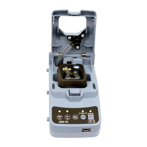
Instrument Cradle The instrument cradle is a recessed area on the top of the SDM-03 that is designed to accept the 03 Series. Insert the 03 Series in the instrument cradle when you perform a bump test or calibration. A spring-loaded cover latches into place to secure the 03 Series. -
Page 14: Back Panel
Two sample fittings are located on the back of the SDM-03. The AIR fitting is in the upper left corner and draws air into the SDM-03. The GAS fitting is to the right of the AIR fitting and is used to connect the SDM-03 to a calibration gas cylinder. Both fittings accept 3/16 inch ID tubing. -
Page 15: Control Panel
EDIT BUMP CAL. COPY ENTER 1SEC ON SDM-03 3SEC OFF Control Buttons Figure 9: Control Panel Five control buttons are located on the control panel. From left to right they are BUMP , CAL , EDIT ENTER, COPY, and POWER. The BUMP... - Page 16 Table 2: Control Button Functions Control Control Button LED Control Button Function(s) Button Function(s) • Initiates a calibration Indicates status of a calibration • Cancels a calibration in progress • Clears data from docking station memory (when used with COPY button) •...
-
Page 17: Front Panel
USB flash drive. This USB port is for use only in the Standalone configuration of the SDM-03. Figure 10: Front Panel NOTE: The SDM-03 does not support connection of a computer to the front USB port, only a USB flash drive. Front Panel • 13 1.800.544.2843 www.calcert.com... -
Page 18: Chapter 3: Preparing To Use The Sdm-03
The tube that is shipped with the SDM-03 has an ID of 5/16 inch and is 10 feet long. Install the 3 foot long 3/16 inch ID tube that is included with the SDM-03 on the GAS fitting. -
Page 19: Setting The Operational Parameters In Edit Mode
The bump test and calibration parameters are saved in the SDM-03’s memory. If a parameter is changed with one particular instrument installed in the SDM-03, the change will be in effect for the bump test or calibration of any subsequent instruments until the parameter is changed again. - Page 20 The air sample time can be set separately for bump testing and calibration. It is the length of time that the SDM-03 will draw air through the AIR fitting on the back of the docking station. Air is drawn during a bump test or calibration before an air adjust operation and to purge calibration gas from the system after calibration gas has been drawn through the GAS fitting on the back of the docking station.
-
Page 21: Turning On The Sdm-03 With An Instrument
Do the following to turn on the SDM-03 and establish a connection with an instrument: Confirm that the AC adapter is connected to the SDM-03 and to an AC wall socket. Press and hold the SDM-03’s POWER button. The LEDs will turn amber. - Page 22 C.LIMIT C.LIMIT The alarm LED and buzzer will pulse several times. The instrument will then connect to the SDM-03 and display the home screen shown above in step 7. • When Cal. Limit Display is set to On, if the unit is due for calibration and if Cal.
-
Page 23: Setting The Bump Test Parameters
Do the following to set the bump test parameters. Turn on the SDM-03 with an instrument and establish a connection between them as described above in "Turning on the SDM-03 with an Instrument". The instrument will display the home screen. - Page 24 Use the BUMP and CAL buttons to scroll through the different bump test parameters. Do not scroll past the AUTO--C parameter until you have finished making any desired changes. AIR--IN GAS--IN TOLER AUTO--C SAVING %LEL CONN To edit a parameter, press and release the EDIT ENTER button when that parameter is displayed.
-
Page 25: Setting The Calibration Parameters
Do the following to set the calibration parameters. Turn on the SDM-03 with an instrument and establish a connection between them as described above in "Turning on the SDM-03 with an Instrument". The instrument will display the home screen. - Page 26 Use the BUMP and CAL buttons to scroll through the different calibration parameters. Do not scroll past the GAS--IN parameter until you have finished making any desired changes. AIR--IN GAS--IN SAVING %LEL CONN To edit a parameter, press and release the EDIT ENTER button when that parameter is displayed.
-
Page 27: Connecting Calibration Gas
HS-03 25.0 ppm H To connect calibration gas to the SDM-03, do the following: If the area around the docking station is not considered a fresh air area (an area free of combustible and toxic gases and of normal oxygen content, 20.9%) install a tube not longer than 10 feet on the filter attached to the AIR... -
Page 28: Installing The Single Module Data Viewer Software
Installing the Single Module Data Viewer Software ® Launch Windows Exit from all applications and open windows. Insert the SDM-GX Product CD into your computer’s CD-ROM drive. The CD will automatically open revealing several folders. Open the Single Module Data Viewer Software folder, double click on setup.exe. -
Page 29: Chapter 4: Operation
Single Module Data Viewer Program. Bump Testing an 03 Series When a bump test is performed, the SDM-03 performs a fresh air adjustment on an 03 Series and then applies calibration gas to the instrument. The docking station then analyzes the response results based on criteria defined by the bump test check tolerance parameter and determines if the instrument passed the bump test. - Page 30 CHANGE BATT The instrument will not connect to the SDM-03 until the batteries are replaced as described in the GP-03 or OX-03/CO-03/HS-03 Operator’s Manual and the instrument is turned back on. 26 • Bump Testing an 03 Series 1.800.544.2843...
- Page 31 C.LIMIT C.LIMIT The alarm LED and buzzer will pulse several times. The instrument will then connect to the SDM-03 and display the home screen shown above in step 7. • When Cal. Limit Display is set to On, if the unit is due for calibration and if Cal.
- Page 32 To perform a calibration, press and release the CAL button. 14. The SDM-03 will begin the bump test by applying fresh air to the instrument for the time defined by the AIR--IN bump test parameter. 15. The SDM-03 will perform a fresh air adjustment on the instrument.
- Page 33 ZERO ZERO Figure 11: Failed Fresh Air Adjustment In this case, continue with step 20. 16. The SDM-03 will apply calibration gas to the instrument for the time defined by the GAS--IN bump test parameter. %LEL BUMP 17. The SDM-03 will analyze the results.
- Page 34 See “Using the Single Module Data Viewer Program” on page 45 for a description of calibration results. 18. The SDM-03 will then purge the system with fresh air for the time defined by the AIR--IN bump test parameter. 19. After the fresh air purge is complete, the 03 Series screen will alternate between the gas reading and the bump test or bump test and calibration result.
- Page 35 EDIT ENTER button. CAUTION: When using the 03 Series with the SDM-03, do not turn off the instrument using the instrument power button. Use the EDIT ENTER and POWER buttons on the SDM-03 to turn off the instrument.
- Page 36 21. The results of the bump test or bump test and calibration will be stored in the SDM-03’s memory and will be available to copy to a USB flash drive. See “Copying Calibration and Bump Test Records to a USB Flash Drive” on page 41 for instructions to copy the saved bump test and calibration records to a USB flash drive.
-
Page 37: Calibrating An 03 Series
03 Series. To perform a calibration on an 03 Series: Confirm that the AC adapter is connected to the SDM-03 and to an AC wall socket. Press and hold the SDM-03’s POWER button. The LEDs will turn amber. - Page 38 CHANGE BATT The instrument will not connect to the SDM-03 until the batteries are replaced as described in the GP-03 or OX-03/CO-03/HS-03 Operator’s Manual and the instrument is turned back on. There are two exceptions to the sequence described in step 7 above. See the 03 Series User Setup Program Operator’s Manual for a description of the Cal.
- Page 39 MODE The alarm LED and buzzer will pulse several times. The instrument will then connect to the SDM-03 and display the home screen shown above in step 7. 10. Verify that the appropriate calibration gas cylinder is connected to the GAS fitting on the back of the SDM-03.
- Page 40 ZERO Figure 16: Failed Fresh Air Adjustment In this case continue with step 18. 15. The SDM-03 will apply calibration gas to the instrument for the time defined by the GAS--IN calibration parameter. %LEL 36 • Calibrating an 03 Series 1.800.544.2843...
- Page 41 16. The SDM-03 will then purge the system with fresh air for the time defined by the AIR--IN calibration parameter. 17. After the fresh air purge is complete, the screen will alternate between the gas reading and the calibration result. If the calibration passed, the auto calibration value will be displayed.
- Page 42 LED will automatically be cleared. 19. The results of the calibration will be stored in the SDM-03’s memory and will be available to copy to a USB flash drive. See “Copying Calibration and Bump Test Records to a USB Flash Drive” on page 41 for instructions to copy the saved bump test and calibration records to a USB flash drive.
-
Page 43: Troubleshooting
Troubleshooting NOTE: This troubleshooting guide describes SDM-03 problems only. See the GP-03 or OX-03/CO-03/HS-03 Operator’s Manual for problems you may encounter with the instrument. Table 5: Troubleshooting the SDM-03 Symptoms Probable Causes Recommended Action • Fresh air • The SDM-03 is not in a 1. - Page 44 • No IR connection • SDM-03 is not turned on. 1. Turn on the SDM-03. If it does not turn on, check that the AC between • The instrument is not adapter is plugged into an AC instrument and correctly inserted into the...
-
Page 45: Calibration And Bump Test Records
200 such records. When an SDM-03’s memory becomes full, the oldest record is overwritten when a new record is saved. The records saved in the SDM-03’s memory can be saved to a USB flash drive using the USB port on the front. Available Memory in the SDM-03 The COPY LED indicates how much of the SDM-03’s memory has been used. -
Page 46: Clearing The Sdm-03'S Memory
Install a USB flash drive into the USB port on the front of the SDM-03. The SDM-03 will take a few seconds to determine how much memory is available in the flash drive. • If the flash drive’s available memory is not enough for the contents of the SDM-03’s memory, the COPY LED will alternate between green and red. -
Page 47: Bump Testing Or Calibrating And Saving Files To A Flash Drive
DAT folder from the SDM-03. The files that an SDM-03 saves to a USB flash drive are structured so that they can be imported into a database controlled by the Single Module Data Viewer Software. See “Importing Files Into the Database” on page 46 for instructions to add files to the database. -
Page 48: Chapter 5: Single Module Data Viewer Program
The Single Module Data Viewer Program is used to view, organize, and print bump test and calibration records that were created by the SDM-03 while used in the standalone configuration. It can also be used to export these records from its database for use in other programs. -
Page 49: Data Viewing Window
In the example above, the data is organized by date. You can do the following in the data viewing window: • Import files into the database that were created by an SDM-03 Using the Single Module Data Viewer Program • 45 1.800.544.2843 www.calcert.com... -
Page 50: Importing Files Into The Database
Print a bump test or calibration report that includes the results and all gas readings. Importing Files Into the Database The files generated by the SDM-03 are structured to be imported into the Single Module Data Viewer Program database. To import data files into the database, do the following: While in the Data Viewing Window, click the Import button. -
Page 51: Organizing The Data
Organizing the Data When viewing the data, it can be organized in two ways: Base View Format In base view format, neither of the Serial No, Station ID, or User ID selection boxes in the lower left of the window are selected and the Base box appears next to these selection boxes with two radio buttons. -
Page 52: Viewing The Data
ID View Format In ID view format, the data can be organized by one or more of the following items depending on which selection box or boxes in the lower left corner of the data viewing window are selected: • Serial Number •... - Page 53 When an item no longer has a (+) or (-) symbol next to it, single click it and the contents of the item will be shown on the right side of the window. If you are viewing data in base view format with the data organized by type, expand the item, bump test or calibration, you wish to view.
- Page 54 If you organize the data by date, then folders organized by year/month appear in the left side of the window. Expand the folder you want to see and click on the calibration or bump test folder. The calibration or bump test files will appear in the upper right side of the window.
- Page 55 If you are viewing data in ID view format, expand the folders in the left side of the window until the bump test or calibration folder you wish to view is visible. Expand the folder by clicking the (+) symbol next to it. Folders organized by year/month will be listed below the calibration or bump test folder.
- Page 56 To view the file contents, click on the file in the upper right part of the data view window that you wish to view. The contents in the file will appear in the lower right part of the window. The contents include the instrument’s serial number, station ID, user ID, bump test or calibration time, test gas, and gas readings during the operation.
-
Page 57: Deleting Data
corner of the window. The Save To File button has a floppy disk icon in it. A “Save As” dialog box will appear for you to specify the filename, file location, and file type. Select the Text files (*.csv) choice to save the information as a comma separated value file that may be opened with a spreadsheet program such as Microsoft Excel. -
Page 58: Changing The Password
Enter the password and click OK. The factory set password is “ABCDE” and is case sensitive. A confirmation window will appear. Click OK to complete the deletion of the selected item. Changing the Password The factory password is “ABCDE” and is case sensitive. You can change the password in the data view window. -
Page 59: Exiting The Program
Enter the new password and click the New Password button. A confirmation window will appear prompting you for the new password again. Enter the new password again and click the Confirm New Password button. A window will appear indicating that the password has been changed. Click OK to complete the password update. - Page 60 49-2058RK-04 4-port AC adapter 71-0359 Operator’s Manual, SDM-03 Docking Station Standalone Configuration (this document) 71-0360 Operator’s Manual, SDM-03 Docking Station PC Controller Configuration 71-8007RK Product CD for SDM-GX Series, includes Single Module Data Viewer Program 81-0012RK-01 Calibration cylinder, 50 %LEL CH...
Need help?
Do you have a question about the SDM-03 and is the answer not in the manual?
Questions and answers