
Related Manuals for Spacelabs Healthcare BleaseSirius


Summary of Contents for Spacelabs Healthcare BleaseSirius
- Page 1 BleaseSirius Anesthesia Systems 073-0212-00 Rev. E | www.spacelabshealthcare.com U S E R M A N U A L BleaseSirius User Manual...
- Page 2 BleaseSirius User Manual...
- Page 3 This User Manual applies to the following software versions: Front Panel Software V10.05 or later Control Board Software V9.61 or later (See section 2.2.27.9 for instructions on how to access information on which software version currently running on the ventilator). BleaseSirius User Manual...
- Page 4 Preface BleaseSirius User Manual...
- Page 5 Preface Section 1 BLEASESIRIUS ANESTHETIC MACHINE Section 2 700/900 SERIES VENTILATORS Section 3 CAS I & II ABSORBER Section 4 NOTICES AND IMPORTANT INFORMATION IMPORTANT The user must be familiar with the machine and its various functions before using it on a patient.
- Page 6 Preface Notes BleaseSirius User Manual...
-
Page 7: Table Of Contents
Contents How to Use This Manual ................19 Section 1 - BleaseSirius ................21 Intended Use ......................24 Introduction .....................25 Description ......................27 1.2.1 General ....................27 1.2.2 The Frame ....................31 1.2.3 Pneumatic Assembly ................31 1.2.4 The Monitor Shelf ..................31 Specifi cation ....................32 1.3.1 Physical ....................32... - Page 8 1.5.5.9 Flowmeter Backlight and Da-lites..........73 1.5.5.10 Maneuvering the Machine ............74 User Maintenance Schedule ................75 Pre-Use Checks ..................75 1.7.1 Gas Supply Hoses and Probes Check ............75 1.7.2 Cylinder and Pipeline Supplies Check .............76 1.7.3 Flowblock Assemblies Check ..............76 BleaseSirius User Manual...
- Page 9 2.1.3 Operating Modes ..................88 2.1.3.1 Volume Control................89 2.1.3.2 Precision Pressure Control ............89 2.1.3.3 SIMV-PC + PSV and SIMV-VC + PSV Modes ......90 2.1.3.4 Inspiratory Pause ...............91 2.1.3.5 Sigh ....................91 2.1.3.6 Advanced Pressure Support .............92 2.1.4 Principles of Operation ................93 BleaseSirius User Manual...
- Page 10 2.1.7 Battery Status LEDs ................104 2.1.8 Menu Tree ....................105 2.1.8.1 Setup Menu ................105 2.1.8.2 Defaults Menu................106 2.1.8.3 Alarm Setup ................106 Using the Ventilator ..................107 2.2.1 Power On the Ventilator .................107 2.2.2 Start the Ventilator .................107 2.2.3 Stop the Ventilator .................108 BleaseSirius User Manual...
- Page 11 2.2.24 User Defi ned Alarms ................141 2.2.24.1 Apnea Alarm................141 2.2.24.2 Low Oxygen Alarm ..............141 2.2.24.3 High Oxygen Alarm ..............141 2.2.24.4 High BPM Alarm ...............141 2.2.24.5 Pressure Limit Alarm ..............141 2.2.24.6 Low BPM Alarm ................142 2.2.24.7 MV High Alarm .................142 BleaseSirius User Manual...
- Page 12 Routine User Maintenance ................161 2.4.1 Monthly Check ..................161 2.4.1.1 Control Unit ................161 2.4.2 Six-Month Check ...................161 2.4.2.1 Bellows ..................161 2.4.3 Other Maintenance ................161 2.4.4 Cleaning and Sterilization ..............162 2.4.4.1 Ventilator Surfaces ..............162 2.4.4.2 Patient Flow Sensor and Tubing ..........162 BleaseSirius User Manual...
- Page 13 3.2.2.1 For Disposable Soda Lime Canister(s) ........191 3.2.2.2 For Reusable Soda Lime Canister(s) ........191 3.2.3 Bag Arm Link Pipe .................192 3.2.4 Attach the Breathing Circuit Tubing ............193 3.2.5 Pre-Use Checks ..................194 3.2.5.1 Compliance Test ..............195 3.2.5.2 Spontaneous Breathing Setup ..........195 BleaseSirius User Manual...
- Page 14 Responsibilities of the Manufacturer .............213 Disclaimer .....................214 Technology Disclaimer / Tamper Proof Seal ..........214 Note to Service Personnel ................214 Copyright .......................215 Trademarks and Acknowledgements ............216 Hazard Notices .....................217 Appendix 1: EMC Tests for IEC 60601-1-2 Compliance ..........250 BleaseSirius User Manual...
- Page 15 Figure 12a - Filter Set Up ...................53 Figure 12b - Filter Set Up ...................53 Figure 13 - Suction Controller ..................54 Figure 14 - BleaseSirius Anesthetic Machine Components ........56 Figure 15 - Pneumatic Circuit for the Mechanical Flowmeter ........62 Figure 16 - Mechanical Flowmeter ................68 Figure 17 - Electronic Flowmeter, 3 Gas Option ............69...
- Page 16 Figure 63 - Fresh Gas Too High (03) ................119 Figure 64 - Fresh Gas Too High (04) ................119 Figure 65 - Fresh Gas Too High (05) ................119 Figure 66- A.C.G.O Screen ..................121 Figure 67 - Oxygen Screen ..................121 Figure 68 - Setup Menu ....................122 BleaseSirius User Manual...
- Page 17 Figure 98 - Auto Set Alarm Buttons ................143 Figure 99 - Alarms Limits Options ................144 Figure 100 - Mute Time Options ................145 Figure 101 - Setting Apnea Time ................145 Figure 102 - PAW <-10cmH O Option ..............146 Figure 103 - Defaults Menu ..................146 BleaseSirius User Manual...
- Page 18 Figure 125 - Non-MRI Manometer ................205 Figure 126 - CAS I/II Absorber Condenser ...............206 Figure 127 - Clamp Plate Screws ................207 Figure 128 - Remove/Reinstall Clamp Plate ............207 Figure 129 - Absorber Lock Components ..............208 Figure 130 - Locking Bar Disengaged ..............209 BleaseSirius User Manual...
-
Page 19: How To Use This Manual
BleaseSirius How to Use This Manual This manual is designed as a guide for learning to operate the BleaseSirius Anesthesia System, and also as a reference tool to use once you are familiar with the system. This manual has four sections: the fi rst contains information about the... - Page 20 This page is intentionally blank BleaseSirius User Manual...
-
Page 21: Section 1 - Bleasesirius
Section 1 BleaseSirius BleaseSirius User Manual... - Page 22 Section 1 - BleaseSirius Anesthetic Machine Symbols and Abbreviations Used Airway Pressure Limiting IEC symbol for alternating current A.C.G.O Auxiliary Common Gas Outlet Read and follow instructions for use. bpm BPM Breaths per minute End of Case Circle Absorber System Oxygen Flush C.G.O...
- Page 23 Section 1 - BleaseSirius Anesthetic Machine Vent Date of Manufacture l/m lpm Litres per minute Light Emitting Diode Millilitres Pressure Support Ventilation Millivolts Tidal Volume Nitrous Oxide psig Pounds per square inch gauge Pedi Sensor Pediatric Sensor Spirometry/Sensor Pplat Plateau Pressure...
-
Page 24: Intended Use
Section 1 - BleaseSirius Anesthetic Machine Intended Use The Spacelabs BleaseSirius Anesthesia Workstation is intended for use in the hospital environment and operating room. It may be used for the delivery of oxygen, air and nitrous oxide in a controlled manner to various patient breath- ing circuits with or without the use of mechanical ventilator, and may be used for the delivery of anesthetic vapor by use of a dismountable vaporizer. -
Page 25: Introduction
All pictures shown in this manual are of the BleaseSirius machine. Note that not all options available for the BleaseSirius are shown in this manual. The BleaseSirius is latex free. Note that any replacement parts must not contain latex. - Page 26 Use only properly designed heat lamps, heat chambers and/or ‘antistatic’ quick-chill sprays during troubleshooting or stress testing procedures. In particular electronic assemblies in the BleaseSirius range of machines are easily damaged by ESD and require special handling. BleaseSirius User Manual...
-
Page 27: Description
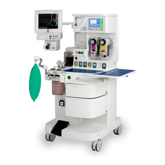
Figure 1 on the next page identifi es the major system components. The BleaseSirius anesthetic machine is designed to comply with the following: • ASTM F-1850 •... -
Page 28: Figure 1 - Bleasesirius Anesthetic Machine
Section 1 - BleaseSirius Anesthetic Machine Figure 1 - BleaseSirius Anesthetic Machine BleaseSirius User Manual... - Page 29 Section 1 - BleaseSirius Anesthetic Machine Figure 1 Key Monitor Shelf Ventilator Vaporizer Cylinder/Pipeline Gauges Pneumatic Unit - (behind gauge panel) Handle Oxygen Flush Common Gas Outlet (or option A.C.G.O.) Drawer Frame Brake Pedal A.G.S.S. Absorber Bag Arm Link Pipe...
-
Page 30: Figure 2 - Back Of Bleasesirius
Section 1 - BleaseSirius Anesthetic Machine Figure 2 - Back of BleaseSirius Figure 2 Key Electrical Socket Bank Electrical On/Off Switch Pipeline Inlets Circuit Breakers Cylinder Yokes Cable and Pipeline Strap Fixing BleaseSirius User Manual... -
Page 31: The Frame
25 kg/55.1 lbs. n the U.S.A., use a cord fi tted with a NEMA 5-15 hospital grade plug to connect the BleaseSirius to the mains power supply. Connection of equipment to the auxiliary mains socket outlets may increase leakage currents to values exceeding the allowable limits. -
Page 32: Specifi Cation
Section 1 - BleaseSirius Anesthetic Machine Specifi cation 1.3.1 Physical 1.3.1.1 Machine Dimensions Height Maximum Width Depth Average Weight 1486 mm/58.5 inches 705 mm/27.7 inches 747 mm/29 inches 110 kg/242.5 lbs 1.3.1.2 Work Surface Dimensions Height Area 854 mm/33.6 inches 98612.2 mm... -
Page 33: Pneumatics
Section 1 - BleaseSirius Anesthetic Machine 1.3.3 Pneumatics 1.3.3.1 Gas-Specifi c Color Specifi cations Color (ISO Countries) Color (ANSI Countries) Oxygen White Green Nitrous Oxide Blue Blue Medical Air Black Yellow 1.3.3.2 Electrical Cable Color Specifi cations Cable Color (230V Machines) -
Page 34: Technical/Performance Specifi Cations
Depending on the system confi guration, a 700- or 900-series ventilator is inte- grated into the BleaseSirius. The units of pressure measurement are cmH O or hPa. The BleaseSirius machine is not suitable for use in an MRI environment. BleaseSirius User Manual... -
Page 35: Alarms/Indicators
Section 1 - BleaseSirius Anesthetic Machine 1.3.4.3 Alarms/ Indicators Oxygen Failure Audible alarm for minimum of 8 secs, when oxygen pressure falls below 225 kPa/32.6 psi. 1.3.4.4 Regulator Safety Valve Settings Cylinder Regulator 310.3kPa/45psi Cylinder Regulator Relief Valve 500kPa/72.5psi Machine Gas Piping Design Rating 700kPa/max. -
Page 36: Gas Flows
Section 1 - BleaseSirius Anesthetic Machine 1.3.4.5.1 Electrical Labeling Figure 3 Key Switched Outlet Label Isolation Transformer Label Figure 3 - Electrical Labeling The units use semiconductor devices which are susceptible to damage by overloading, reversed polarity, electrostatic discharge and excessive heat or radiation. -
Page 37: Ancillary And Optional Features
Section 1 - BleaseSirius Anesthetic Machine 1.3.5 Ancillary and Optional Features Standard Features • Integrated 700/900 Series Ventilator • 2-Position Selectatec Backbar • Simplex– Single Tube Mechanical Flowmeter (O ), with Backlighting • O Pipeline Inlet Fitting • Integrated Suction Regulator •... - Page 38 Section 1 - BleaseSirius Anesthetic Machine Required Features • Air and/or N O pipeline fi ttings (Note: If the system has the electronic fl owmeter, it can have 2-gas fi ttings, O and Air) • Anesthetic Gas Scavenging System • Drawer Options •...
-
Page 39: Vaporizers
Section 1 - BleaseSirius Anesthetic Machine 1.3.5.1 Vaporizers Datum Vaporizers with Standard Fillers Part Number Selectatec Mounting Halothane calibrated to 5% v/v 13022218 Enfl urane calibrated to 5% v/v 13032218 Isofl urane calibrated to 5% v/v 13012218 Sevofl urane calibrated to +8% v/v... -
Page 40: Installation
Many of the installation steps given in the following sections are performed by a Spacelabs Healthcare service representative. However, you may need to disconenct/reconnect certain components during use, maintenance or sterilization. Always verify that the system is properly setup any time you disconnect, then reconnect components. -
Page 41: Figure 4A - Installing The Cylinders
Section 1 - BleaseSirius Anesthetic Machine Figure 4a Key Cylinder Yoke Locking Handle Bridge Figure 4a - Installing the Cylinders Figure 4b Key Inlets Securing Straps Securing Chains Large Cylinder Tray Figure 4b - Installing Large Cylinders BleaseSirius User Manual... -
Page 42: Install The Large Cylinders (Optional)
Section 1 - BleaseSirius Anesthetic Machine Align the yoke’s connector and pins with the corresponding holes in the cylinder valve, then push the cylinder into the opening of the yoke so that the connector is fully engaged. 10. While supporting the cylinder from underneath, close the cylinder yoke. by turning the bridge clockwise until its cutout is fully engaged in the coupling on the yoke body. -
Page 43: Connect The Pipelines
Section 1 - BleaseSirius Anesthetic Machine 1.4.2 Connect the Pipelines Remove and discard the protective caps from the pipeline inlets. Ensure that each pipeline (O O, MED AIR and scavenging and suction) is coupled to the appropriate inlet by noting which gas is marked on the inlet. -
Page 44: Figure 5 - Connect The Oxygen Sensor
Section 1 - BleaseSirius Anesthetic Machine Step 1 Step 2 Step 3 Figure 5 - Connect the Oxygen Sensor BleaseSirius User Manual... -
Page 45: Guidelines For Handling The Oxygen Sensor
Never disassemble or modify the oxygen sensor. 1.4.4 Install the Selectatec Vaporizers You can fi t a maximum of two vaporizers to the BleaseSirius backbar manifold. Remove the protective caps from the inlet ports on the vaporizer. Discard the caps. - Page 46 Section 1 - BleaseSirius Anesthetic Machine Vaporizer Warnings Refer to the vaporizer operating manual before use, for fi lling, operating and service instructions. The manual also contains information concerning the extent to which the delivered vapor concentration is affected by changes in ambient temperature and pressure, and accuracy and calibration details, which should be understood before use.
- Page 47 Section 1 - BleaseSirius Anesthetic Machine Maintain suffi cient fresh gas fl ow when using sevofl urane. To remove a vaporizer from the backbar: Position the vaporizer control dial to Off. Turn the vaporizer locking lever fully counter-clockwise to release the vaporizer.
-
Page 48: Figure 6 - Cas Absorber And Components
Section 1 - BleaseSirius Anesthetic Machine Figure 6 Key APL Valve Bypass Switch (optional) (not available in the USA) Expiratory Non-return Valve Canister Bag Arm Link Pipe [Bag Port] (Optional) Patient Expiratory Connector (22 mm male and 15 mm female taper) -
Page 49: Install The Cas Absorber
Section 1 - BleaseSirius Anesthetic Machine 1.4.5 Install the CAS Absorber The absorber is supported on a two-prong assembly, which is mounted on the left side of the machine. Align the mounting holes on the back of the absorber with the horizontal prongs on the left side of the BleaseSirius (Figure 7). -
Page 50: Install The Extended Work Surface (Optional)
Section 1 - BleaseSirius Anesthetic Machine 1.4.6 Install the Extended Work Surface (Optional) The extended work surface for the BleaseSirius is must be installed on site by a qualifi ed Technical Engineer. Only qualifi ed Technical Engineers are authorized to fi t the extended work surface assembly. -
Page 51: Patient Airway Flow Sensor
Section 1 - BleaseSirius Anesthetic Machine 1.4.7 Patient Airway Flow Sensor The adult sensor is shown in the following sections for instructional purposes. The Pedi Sensor is set up in the same manner Flow Sensor Tubing Sample tube can be retained with patient airway fl... -
Page 52: Filter
Section 1 - BleaseSirius Anesthetic Machine If the gas sample line is not in use, then replace white cap. The Pedi Sensor does not have a gas sampling port. The machine is to be equipped with an anesthetic gas scavenging system, complying with ISO 8835-3 or applicable local standard before being put into service. -
Page 53: Figure 12A - Filter Set Up
Section 1 - BleaseSirius Anesthetic Machine Pic. 1: This setup is Sensor INCORRECT. The small diameter tubing of the patient circuit can cause jetting to front port of the fl ow sensor. This will To patient lead to exceptionally high VTE... -
Page 54: Suction Controller
Section 1 - BleaseSirius Anesthetic Machine 1.4.8 Suction Controller Mode Switch 1.4.8.1 Fitting the Suction Controller The suction system consists of a suction controller and a receiver jar. The suction controller is built into the trolley on the upper left corner of the machine, behind the bellows. -
Page 55: Suction Controller Features
Section 1 - BleaseSirius Anesthetic Machine 1.4.8.2 Suction Controller Features **Maximum fl ow is affected by vacuum source and fi ttings. 1.4.8.3 Testing the Suction System After installing the suction system, perform a simple adjustment and test: In the Continuous Mode: Turn the Mode switch to REG. -
Page 56: Figure 14 - Bleasesirius Anesthetic Machine Components
Section 1 - BleaseSirius Anesthetic Machine Figure 14 - BleaseSirius Anesthetic Machine Components BleaseSirius User Manual... - Page 57 Section 1 - BleaseSirius Anesthetic Machine Figure 14 Key Monitor Shelf Ventilator Vaporizer Cylinder/Pipeline Gauges Pneumatic Unit - (behind gauge panel) Handle Oxygen Flush Common Gas Outlet (or option A.C.G.O) Drawer Frame Brake Pedal A.G.S.S. Absorber Bag Arm Link Pipe...
-
Page 58: Ventilators
Theory of Operation Upon receipt of new machines, you should sterilize/clean all components of the BleaseSirius anesthesia machine before use. Refer to Figure 14 on page 56 as you read this section. The gas supply inputs consist of the pipeline inlets and cylinder yokes, that couple and secure the gas cylinders to the machine, and its pneumatics. - Page 59 Section 1 - BleaseSirius Anesthetic Machine The gases fl ow from the pneumatic valves through the fl ow control valves and their fl owblock assemblies. Each gas has an associated fl ow control valve and fl owblock assembly. Turn the fl ow control valve dials counter-clockwise to increase the gas fl...
- Page 60 Section 1 - BleaseSirius Anesthetic Machine The On/Off switch (P) is located on the front of the fl owblock assembly and is used to turn all the gases of the machine on or off (except the supply to the oxygen fl ush control and the oxygen/air power outlet). The switch is turned clockwise to turn the machine on and counter-clockwise to turn it off.
-
Page 61: C.g.o. Pressure Relief Valve
Section 1 - BleaseSirius Anesthetic Machine 1.5.1 C.G.O. Pressure Relief Valve The machine is equipped with various pressure limiting devices to protect both the patient and the user. • The C.G.O. is set between 3 and 4 psi/27.6 to 34.5 kPa. -
Page 62: Figure 15 - Pneumatic Circuit For The Mechanical Flowmeter
Section 1 - BleaseSirius Anesthetic Machine Figure 15 - Pneumatic Circuit for the Mechanical Flowmeter Figure 15 Key Air Pipeline Air Cylinder Yoke O Pipeline O Cylinder Yoke Pipeline Cylinder Yoke Failure Alarm Valve Reservoir Failure Whistle BleaseSirius User Manual... - Page 63 Section 1 - BleaseSirius Anesthetic Machine Figure 15 Key Air Takeover Valve O Cutoff Valve Failure Alarm Switch On/Off Switch Vent Supply Air Secondary Regulator O Secondary Regulator Oxygen Secondary Regulator Oxygen Flush Air Flowmeter or Air Flow Sensor (on...
-
Page 64: Oxygen System And Oxygen Failure Warning Device
Oxygen System and Oxygen Failure Warning Device The BleaseSirius machines are fi tted with a pneumatic circuit (See Figure 15). Oxygen is conducted from each oxygen yoke block (F), if installed, to the appropriate high pressure oxygen regulator input and cylinder contents gauge which indicates the cylinder pressure. - Page 65 Section 1 - BleaseSirius Anesthetic Machine When the On/Off switch (M) is turned On, oxygen is supplied to the oxygen fl ow control (via the secondary regulator (Q), the reservoir (H) and control inputs of the other gases’ cutouts. An alarm sounds on the ventilator.
-
Page 66: Nitrous Oxide System (Optional)
Section 1 - BleaseSirius Anesthetic Machine 1.5.3 Nitrous Oxide System (Optional) If your machine has the electronic fl ow meter, air is the madatory second gas. Nitrous oxide is optional. Nitrous oxide is conducted from each nitrous oxide yoke block (D) to the appropriate high-pressure nitrous oxide regulator input and cylinder contents gauge which indicates the cylinder pressure. -
Page 67: Medical Air System (Optional)
Section 1 - BleaseSirius Anesthetic Machine The nitrous oxide passes from the fl ow tube/fl ow sensor into a mixing chamber where it mixes with the other gases, and then to the vaporizer backbar or manifold assembly. It then passes through the vaporizer (Y) where it picks up an anesthetic vapor and passes to the common gas outlet (X) of the machine via a non-return valve. -
Page 68: Controls
fl ow tube with a rotating fl oat and a dial for each gas. A cascade-style fl owmeter option is also available for the BleaseSirius. The cascade style has a small low-fl ow and a larger high-fl ow tube for each gas. The fl... -
Page 69: Figure 17 - Electronic Flowmeter, 3 Gas Option
ISO-specifi cation machines and on the extreme right on ANSI-specifi cation machines. The EFM powers on when the system powers on. The Spacelabs Healthcare logo is displayed during boot-up. If you see the warning triangle on the EFM screen at any time, do not use the machine. -
Page 70: Figure 18- Gas Consumption Data, System Information Screen
21°C (70°F) and 1013 mbar. EFM-Specifi c Alarms If you see the warning triangle on the EFM screen at any time, do not use the machine. Contact your local Spacelabs Healthcare service representative or Spacelabs Global Technical Support as soon as possible. -
Page 71: Auxiliary Flowmeter
Section 1 - BleaseSirius Anesthetic Machine 1.5.5.3 Auxiliary Flowmeter A built-in auxiliary oxygen fl owmeter provides an independent O supply to the mechanical fl owmeter (or EFM, if installed). 1.5.5.4 Oxygen Flush, O + Button The oxygen fl ush button (O +) is located on the front of the machine below the work surface. -
Page 72: Vaporizers
Section 1 - BleaseSirius Anesthetic Machine Excessive force applied to the fl ow control valves may damage the hypoxic guard. To reduce the oxygen fl ow to zero, turn the machine On/ Off switch to OFF. 25% O is the minimum nominal mixture. The tolerance is 21-30% throughout the range, except where N O is set to 10.0 lpm when it is 21-... -
Page 73: Drawers
Section 1 - BleaseSirius Anesthetic Machine 1.5.5.8 Drawers The BleaseSirius is fi tted with either 1,2 or 3 drawers, depending on the system confi guration. The drawer(s) slide open and closed . To lock the drawers: • Insert the key into the lock located on the right side of the drawer. -
Page 74: 1.5.5.10 Maneuvering The Machine
Section 1 - BleaseSirius Anesthetic Machine 1.5.5.10 Maneuvering the Machine When maneuvering the anesthesia machine, ensure that the brake pedal is released. Always use the system handles to move the machine. Left Side Handle Right Side Handle Figure 20 - System Handle Locations... -
Page 75: User Maintenance Schedule
User Maintenance Schedule Refer to the recommendations of your local professional association regarding maintenance checklists. Instructions for maintaining the BleaseSirius machine are provided by Spacelabs Healthcare in Sections 1.7 through 1.10. During certain maintenance or sterilization procedures, system components may be disconnected. Always confi rm that your system is setup properly anytime you disconnect system components. -
Page 76: Cylinder And Pipeline Supplies Check
Section 1 - BleaseSirius Anesthetic Machine 1.7.2 Cylinder and Pipeline Supplies Check Check that all the cylinders are securely and correctly mounted in their yokes. Disconnect all the pipeline supplies and turn off all gas cylinders. Turn on each cylinder in turn and check that its contents gauge registers an adequate supply of gas. -
Page 77: Leak Test -Vaporizers
Section 1 - BleaseSirius Anesthetic Machine Check the following: a. As the remaining oxygen is depleted, the oxygen failure warning whistle is activated for at least 8 seconds; b. The gas fl ows through the fl owblock assemblies are all stopped, except MED AIR. -
Page 78: Safety Valve
Section 1 - BleaseSirius Anesthetic Machine 1.7.6 C.G.O. Safety Valve Occlude the C.G.O. outlet. Push the fl ush tap. Listen for an audible sound indicating the valve is functioning. 1.7.7 A. C.G.O. Safety Valve (if installed) Occlude the A.C.G.O. outlet. -
Page 79: Full System Test
Section 1 - BleaseSirius Anesthetic Machine Full System Test 1.8.1 Leak Test Ensure that: • Only one cylinder of each gas is installed securely and correctly to the machine, if the system has cylinder(s) installed. • No pipelines are connected to the machine. -
Page 80: On/Off Switch And Warning System Checks
Section 1 - BleaseSirius Anesthetic Machine 1.8.2 On/Off Switch and Warning System Checks Switch on the machine . If the oxygen supply failure alarm operates for more than a few seconds, check that oxygen supply cylinders or pipeline are correctly installed and are at the correct pressure. -
Page 81: Mechanical Hypoxic Guard Test
Section 1 - BleaseSirius Anesthetic Machine 1.8.3 Mechanical Hypoxic Guard Test The machine has a mechanical hypoxic guard installed. Test its function as follows. Turn the oxygen and nitrous oxide fl ow control valves fully clockwise. Check that the oxygen fl ow indicated on the oxygen fl owblock assembly is 150ml/min ±... -
Page 82: Ventilator Test
Section 1 - BleaseSirius Anesthetic Machine 1.8.7 Ventilator Test Connect oxygen supply to the machine and check that ventilator is functioning. See Section 2.2.7 “Pre-use Testing” in this manual for instructions on compliance and system testing of the ventilator. These tests should be performed daily. -
Page 83: Section 2 - 700/900 Series Ventilators
Section 2 700/900 Series Ventilators BleaseSirius User Manual... - Page 84 ü ü ü Flow Waveform ü ü ü ü Spirometry Loops ü Data Output ü ü ü ü ü ü The 730 Ventilator only supports SIMV-VC+PSV mode. The Pressure Control modes are not available on this model. BleaseSirius User Manual...
-
Page 85: Description Of The Ventilator
Variations are based on the drive gas used (MED AIR or oxygen) and the drive gas connector type (depending on the eventual country of use). See Section 2.7 Associated Equipment and Accessories for ordering information for the various types. Figure 21 - 900 Series Ventilator BleaseSirius User Manual... -
Page 86: Features
The alarms are audible and visible. When activated, the alarms are listed on the display. The mains and battery alarms also have light emitting diode (LED) indication Do not block the drive gas exhaust. Blocking the drive gas exhaust may impede ventilator function. BleaseSirius User Manual... -
Page 87: Waveforms And Spirometry
2.1.2.8.1 Low Battery Indicator The mains fail alarm will be activated and a battery symbol will appear in the alarms panel. Symbol indicates how much charge is left in the battery. Figure 22 - Low Battery Indicator BleaseSirius User Manual... -
Page 88: Operating Modes
(<150 ms). Pressure limiting is a safety feature. It should not be used for any other purpose, such as creation of micro-breaths or emulation of specialized high frequency/low volume ventilation systems, otherwise injury to the patient may result. BleaseSirius User Manual... -
Page 89: Volume Control
The effect of Volume and Pressure modes on the pressure and fl ow waveforms is shown below: Volume Control Mode Precision Pressure Control Mode (PCV) Figure 23- Volume & Precision Pressure Control Mode Waveforms BleaseSirius User Manual... -
Page 90: Simv-Pc + Psv And Simv-Vc + Psv Modes
When actually in an SIMV mode: 1. When increasing the BPM, limit the highest BPM value to a point where the I:E ratio becomes 2:1. When increasing Inspired Time, limit the Inspired Time to a point where the I:E ratio becomes 2:1. BleaseSirius User Manual... -
Page 91: Inspiratory Pause
The default percentage is 10% and default frequency is once every tenth breath. The fresh gas fl ow compensation will continue to function during a set pause period. BleaseSirius User Manual... -
Page 92: Advanced Pressure Support
In Pressure mode, bpm, tidal volume and I:E ratio are all monitored values. The user must set two parameters: • the Trigger Threshold (1 L/min to 15 L/min), • the Support Pressure which is referenced to the PEEP level (3 to 20cmH Figure 25 - Pressure/Flow/Volume Waveform BleaseSirius User Manual... -
Page 93: Principles Of Operation
O ± 2cmH O by relieving the drive pressure on the bellows. NEEP is not supported by this machine, but patient generated pressures may be measured to - 10cmH O, at which point an alarm will sound. BleaseSirius User Manual... -
Page 94: Figure 26 - Pneumatic System
Section 2 - 700/900 Series Ventilators Figure 26 - Pneumatic System BleaseSirius User Manual... -
Page 95: Parameters
The value being adjusted could either be the PEEP level or the relevant pressure control. The user can: • Accept the value being adjusted, in which case it will be set to the nearest acceptable value. BleaseSirius User Manual... -
Page 96: Support Pressure
Service Mode. Contact your local Spacelabs representative for more information. 2.1.5.6 Tidal Volume Volume to be delivered by the ventilator in each breath. Range: 20ml to 1500ml all modes. BleaseSirius User Manual... -
Page 97: Minute Volume
2.1.5.13 Peak Pressure Range: 0cmH O to 100cmH 2.1.5.14 Mean Pressure Range: 0cmH O to 100cmH 2.1.5.15 Plateau Pressure (Pplat) Range: 0cmH O to 100cmH 2.1.5.16 Compliance System compliance in ml/ cmH Patient compliance in ml/ cmH BleaseSirius User Manual... -
Page 98: 2.1.5.17 Volume Measurement
± 10% or 0.2L from 0.3L to 15 liters, which ever is the greater. 2.1.5.18 Oxygen Measurement • Oxygen Concentration accuracy = ± 3%. • Drift < 1% over 8 hours at constant temperature. • Response time < 30 seconds for 90% change. BleaseSirius User Manual... -
Page 99: User Interface
Front Panel The front panel of the 700/900 series ventilator has the following controls and indicators: Figure 28 - Ventilator Front Panel Figure 28 Key LCD Touch Screen (Blease700 is monochrome, Blease900 is color.) Battery-Status LED Trak Wheel BleaseSirius User Manual... -
Page 100: Normal Screen
The activity area includes a graphical display updated in real time to show the breathing cycle. The graph is auto-scaled to fi t on the y-axis and to show three cycles on the x-axis. Figure 31 Key Waveform Display Peak Marker Status Line Figure 31 - Activity Display Area BleaseSirius User Manual... -
Page 101: Alarms Display Area
If a parameter has a pre-set level, as well as a monitored value, the pre-set level is indicated at the bottom left of the parameter window and the monitored value is shown in the larger font to the right of the window. BleaseSirius User Manual... -
Page 102: Trak Wheel™ & Touch Screen
2.1.6.6.1.2 To Change a Parameter Setting When a parameter is selected, turn the Trak Wheel clockwise to increase the numerical value or counter-clockwise to decrease the value. Press the Trak Wheel when the desired value is displayed to confi rm the setting. BleaseSirius User Manual... - Page 103 Touch Return until the Normal screen is displayed. If you do not touch the Confi rm button, the original value will be restored. If you do not make a selection within 30 seconds, the menu will timeout and the original value will be restored. BleaseSirius User Manual...
-
Page 104: Battery Status Leds
The green light shows whenever the charge unit is active and should not be interpreted as a direct indication of battery status. Additional battery status information (Volts) may be obtained from the ‘System Information’ screens - See section 2.2.27.9. BleaseSirius User Manual... -
Page 105: Menu Tree
Section 2 - 700/900 Series Ventilators 2.1.8 Menu Tree 2.1.8.1 Setup Menu Figure 33 - Setup Menu Tree BleaseSirius User Manual... -
Page 106: Defaults Menu
Section 2 - 700/900 Series Ventilators 2.1.8.2 Defaults Menu Figure 34 - Defaults Menu Tree 2.1.8.3 Alarm Setup Figure 35 - Alarm Setup Menu Tree BleaseSirius User Manual... -
Page 107: Using The Ventilator
Standby mode, with monitoring in standby. 2.2.2 Start the Ventilator To start the ventilator, turn the BAG/VENT switch on the absorber to VENT. Figure 36 - Bag/ Vent Switch - Vent BleaseSirius User Manual... -
Page 108: Stop The Ventilator
The patient airway fl ow sensor must be installed the patient breathing circuit (see section 2.2.17 for positioning) and the associated sensor tubing must not be trapped, kinked, split or damaged in any way to ensure correct performance. BleaseSirius User Manual... -
Page 109: Figure 39 - Pre-Use Opening Screen At Power-On
Shown at the top of the next page, the left screen is displayed if the analyzer is scav- enged. The right screen is displayed if the analyzer exhaust is returned to the circle. BleaseSirius User Manual... -
Page 110: Figure 42 - Pre-Use Occlusion Tests Screens
Having measured the dead space at the start, the leak test displays the upper left screen and concludes with the upper right screen after 20 seconds. Next, set the Absorber to ‘Bag’ to complete the Compliance Test. BleaseSirius User Manual... -
Page 111: Figure 44 - Perform System Check Screen
Figure 45 - System Test structed making the necessary observations that all Confi rmation Screen components are working correctly. Select Confi rm when you have completed each set of instructions. Figure 46 - System Test Screens BleaseSirius User Manual... -
Page 112: Figure 47 - Compliance Check Passed Message
Check Passed: <Date> <Time>” above the Activity area on the Standby screen. For System Check information, see Page 2 of the System Information (on the Setup > Confi guration menu).The system is ready for use. Figure 47 - Compliance Check Passed Message BleaseSirius User Manual... -
Page 113: Pre-Use Test Error Messages
(Figure 49). Figure 49 - Pre-use Test Error Message (02) Error 03 The Fresh Gas is too High. Reduce the fresh gas fl ow and restart the system test. Figure 50 - Pre-use Test Error Message (03) BleaseSirius User Manual... -
Page 114: Figure 51 - Pre-Use Test Error Message (04)
Check the pipeline/cylinder gauges for the correct gas supply. Figure 52 - Pre-use Test Error Message (05) Error 06 The bellows are empty. Fill the bellows and select Confi rm to continue. Figure 53 - Pre-use Test Error Message (06) BleaseSirius User Manual... -
Page 115: Figure 54 - Pre-Use Test Error Message (07)
If a leak is detected, the causes listed on the screen are possible places to check. Note that these are not the only possibilities. Small holes in the sensor tubing and cracks in breathing circuits may also cause leaks. Figure 55 -Pre-use Test Error Message (08) BleaseSirius User Manual... -
Page 116: Absorber Not Installed
This gives a volume at the “Y” piece that is constant. In some situations when the normal correction cannot be completed, the ventilator alarms. The screen displays a message instructing you how to proceed when correction cannot be made by reducing drive gas. BleaseSirius User Manual... -
Page 117: Standby/Bag Modes
STANDBY mode to Bag mode and “BAG” is displayed on the screen. In this condition, all relevant alarms are active. The alarms not in use at this time are: • Pressure Low • MV Low BleaseSirius User Manual... -
Page 118: Figure 60 - Standby Screen
fl ow will be low, and where the suggested calculated fresh gas fl ow is more Figure 62 - Fresh Gas Too High than 3 lpm, the alarm section displays “Reduce Screen (02) Fresh Gas.” BleaseSirius User Manual... -
Page 119: I:e Setting
Figure 64 - Fresh Gas Too High (04) If nothing happens during the fi rst 12 seconds of the alarm, the suggested I:E value will be implemented. The alarm will continue to sound. Figure 65 - Fresh Gas Too High (05) BleaseSirius User Manual... -
Page 120: Oxygen Calibration
Stop the fl ow of pure oxygen and expose the probe to room air for a few minutes. The oxygen concentration should nominally read 20.9+/-0.5%. To prevent inaccurate calibration, the ventilator will check to ensure the correct percentage of oxygen is present for the selected calibration point. BleaseSirius User Manual... -
Page 121: Calibration With A.c.g.o. System
fl ow to basal. Remove O probe and ‘T’ piece from A.C.G.O. Figure 67 - Oxygen Screen 10. Replace the O probe into the absorber and set the A.C.G.O/C.G.O switch to C.G.O position, if ventilation is required. BleaseSirius User Manual... -
Page 122: The Measurements Menu
You follow the same process to remove a parameter from a button. Select Return to close Measurements Selection Menu. Select Return to close the Confi guration Figure 70 - Measurements Menu menu and display the normal screen. BleaseSirius User Manual... -
Page 123: Adult And Pediatric Modes
If the ventilator is in Standby mode, the switch over is immediate. To reactivate the ventilator, turn off A.C.G.O., switch to Bag mode, then back to Vent mode. 100% oxygen calibration is NOT available when in A.C.G.O. mode (see Section 2.2.13). BleaseSirius User Manual... -
Page 124: Types Of Flow Sensors
200 ml. This capability is useful if you do not have a pediatric sensor or if the pediatric sensor readings differ from the settings. When using adult fl ow sensor for pediatric patients, Spacelabs Healthcare recommends that you set the Patient mode to Adult and the Sensor Type to Sensor At Patient. -
Page 125: Sensor Placement
(Adult or Pediatric) you will use to ventilate the patient. Turn the absorber switch to VENT to start the ventilator. When the adult sensor is at the absorber expiratory port, the ventilator can only be run in Volume Control and Pressure Control modes. BleaseSirius User Manual... - Page 126 Position the patient airway fl ow sensor tubing with care. If the tubing is pinched or cut, the ventilator’s volume monitoring may not function properly. BleaseSirius User Manual...
-
Page 127: Figure 77 - Airway Sensor Placement - Sensor At Patient And Sensor At Absorber
Y connector. If the sensor is installed incorrectly or the sensor placement selection is incorrect, volume data will be inaccurate and associated alarms, including the low minute volume alarm will not function properly. BleaseSirius User Manual... -
Page 128: The Waveform Select Menu
Previous Peak Real Time Pressure Level Figure 79 - Airway Pressure Bar 2.2.19 Save a Spirometry Loop After you select a spirometry waveform, the Store Loop option is displayed. Figure 80 - Store Loop BleaseSirius User Manual... -
Page 129: 2.2.19.1 Recall A Spirometry Loop
Turn off the recalled loop by displaying “Off” on the Store Loop button. Step 1: Highlight Step 2: Select a Store Loop Loop by saved button time Step 4: Turn Off Saved Loop Display Figure 82 - Store Loop Options BleaseSirius User Manual... -
Page 130: 2.2.19.2 Example Spirometry Loops
Figure 85 - Bronchospasm Loop Figure 87 - Patient Breathing with Vent Figure 86 - Kinked Tube (e.g. Lack of relaxation) Loop Loop 2.2.19.2.2 Flow/Volume Loops Figure 88 - Cuff or Laryngeal mask Leak Loop and Kinked Tracheal Tube Loop BleaseSirius User Manual... -
Page 131: Figure 89 - Intro-Abdominal Co2 Insuffl Ation Loop
* (The occurrence of pneumothorax was confi rmed through fl uoroscopy) Figure 90 - Pneumothorax Occurs Loop III. Treatment with PEEP - Compliance improves - Pplat decreases gradually - ETC0 decreases Defl ation of the abdomen Figure 91- PEEP Treatment Loop BleaseSirius User Manual... -
Page 132: Airway Pressure Waveform
Inspired fl ow to the patient is green and expired fl ow from the patient is blue. Expired Flow from Patient Zero Baseline Inspired Flow to Patient Figure 93 - Expired Flow from and Inspired Flow to Patient BleaseSirius User Manual... -
Page 133: Ventilation Mode Menu
Pause is available in the Volume Control and SIMV-VC + PSV ventilation modes. To select a percent pause: Select Pause on the Mode menu. Select the percent pause. Press Return to confi rm your selection. Press Return again to display the Normal Figure 96 - Pause Options screen. BleaseSirius User Manual... -
Page 134: 2.2.21.2 Pause + Sigh Settings
An audible alarm indicates an abnormal condition that may result in injury to the patient or damage to the equipment. Always investigate the cause of an alarm and take necessary measures to resolve the alarm condition. The high and low pressure alarms are important for patient safety. BleaseSirius User Manual... -
Page 135: Figure 97 - Alarm Screen
Check alarms periodically at clinically suitable intervals. If the audible alarm or visual indicator of any alarm function fails to activate during any alarm condition, or fails to reset after the alarm has been cleared, contact Spacelabs Global Technical Support for assistance. BleaseSirius User Manual... -
Page 136: 2.2.23.1 Alarms Summary
Do not set alarms to extreme values because those settings can cause the alarm system to operate incorrectly. Alarms marked with a (*) are inhibited for 20secs, when the ventilator mode is changed. Refer to Alarms Summary. BleaseSirius User Manual... -
Page 137: 2.2.23.2 Pre-Set Alarms
If the supply gas pressure is reduced, the patient minute volume may be reduced and injury to the patient could result. Do not use the ventilator if the supply pressure cannot be maintained. 2.2.23.2.5 Sensor Error Alarm This alarm activates if the sensor is unplugged or faulty. BleaseSirius User Manual... - Page 138 Do not use the ventilator on a patient while this alarm is activated. Do not set alarms to extreme values that can cause the alarm system to function incorrectly. If the Vent Inoperative alarm occurs, contact a qualifi ed technical engineer. BleaseSirius User Manual...
- Page 139 To restore power to the display, press a key or turn the Trak Wheel. The ventilator continues to function normally, powered by its internal battery for a minimum of 30 minutes. Typical operating time is a minimum of 60 minutes. BleaseSirius User Manual...
- Page 140 Generally caused by disconnected or blocked spirometry tubing. 2.2.23.2.18 Sensor Not Detected This alarm is activated if there is no positive or negative fl ow detected from the patient fl ow sensor. BleaseSirius User Manual...
-
Page 141: User Defi Ned Alarms
Range: 18 % to 109 % This alarm is activated when the monitored oxygen level falls below the set level. You can disable this alarm. Contact Spacelabs Healthcare Technical Support or your local Spacelabs representative for more information. 2.2.24.3 High Oxygen Alarm... -
Page 142: 2.2.24.6 Low Bpm Alarm
The alarm is automatically cleared on the second breath that exceeds the alarm limit, if it occurs within 20 seconds. The pressure low alarm is activated if the pressure falls below the set PEEP + 5cmH O for more than 20secs. BleaseSirius User Manual... -
Page 143: Auto Alarms
The user can restore the previous set of alarm limits at any time by either selecting Off in the auto box, or going into the Alarm Limits Menu and making no changes. BleaseSirius User Manual... -
Page 144: The Alarms Setup Menu
Press the up/down arrows or turn the Trak Wheel clockwise to increase or counterclockwise to decrease the value. When the desired value is displayed, press the Trak Wheel or press Confi rm to select the value. Select Return to close the screen and return to the alarm options. BleaseSirius User Manual... -
Page 145: 2.2.26.2 Alarm Mute
Select the desired amount of time to trigger the Apnea alarm. A checkmark in the box next to an option indicates that it is selected. Select Return to close the menu. Figure 101 - Setting Apnea Time BleaseSirius User Manual... -
Page 146: Selecting/Deselecting Paw <-10Cmh O
Before you select Settings or the Defaults, select the correct patient mode (Adult or Pediatric). Certain options on the Defaults Menu are password protected. Contact Spacelabs Healthcare Technical Support or your local Spacelabs representative for more information, if needed. BleaseSirius User Manual... -
Page 147: 2.2.27.1 Save Hospital Default Settings
This menu option allows you to the change the default start up settings as Hospital Default Settings. This option is password protected. Contact Spacelabs Healthcare Technical Support or your local Spacelabs representative for more information. To change the Default Settings: Select the Defaults button. -
Page 148: 2.2.27.3 Change Names
10 characters or spacesto complete the name. Press the Trak wheel at the 10th character to save the name. Repeat steps 3-7 to enter more names for the settings or to change a name previously entered. Select Return to display the Default Menu. BleaseSirius User Manual... -
Page 149: 2.2.27.4 Save Current Settings
Select Change Password. Enter old password and Confi rm your entry. At the prompt, enter the new password and reenter it at the prompt, then Confi rm. Figure 106 - Change Password The new password is saved. Option Selected BleaseSirius User Manual... -
Page 150: Confi Guration
/ replacement and system validation. These options are password protected. Contact Spacelabs Healthcare Technical Support or your local Spacelabs representative for more information. 2.2.27.9 System Information This two-page list shows details about the ventilator status. -
Page 151: 10System Audit Trail
Section 2 - 700/900 Series Ventilators 2.2.27.10 System Audit Trail This function is password protected. To access system audit information, contact your local Spacelabs Healthcare representative. The system audit function stores events about the machine and the ventilator, including: • When unit was powered ON/OFF. -
Page 152: Installation
The ventilator may be adversely affected by the operation of equipment such as high frequency surgical (diathermy) equipment, defi brillators or short-wave therapy equipment in the vicinity. Connection of equipment to the auxiliary mains socket outlets may increase leakage currents to values exceeding the allowable limits. BleaseSirius User Manual... - Page 153 EXHAUST port of the bellows base. This will increase the pressure inside the bellows and cause it to detach from the base, resulting in a serious malfunction. Any problem arising from an improperly functioning scavenging system is solely the responsibility of the user. BleaseSirius User Manual...
-
Page 154: Pre-Use Checks
Refer to the Troubleshooting section in this manual for help. If the malfunction cannot be rectifi ed, contact an authorized Spacelabs Healthcare technical engineer for assistance or return the ventilator to your local representative. - Page 155 60% and verify the oxygen low alarm operates. Set the high oxygen alarm level to 40% and verify that the oxygen high alarm operates. Always perform the pre-use check procedures for volume sensing functions after cleaning or replacing the volume sensor. BleaseSirius User Manual...
-
Page 156: Discharged Battery
30 minutes. Typical operating time is a minimum of 60 minutes. To preserve battery life, never store the ventilator with its battery discharged. Do not store or use the ventilator in close proximity to heat sources of any kind. BleaseSirius User Manual... -
Page 157: Figure 109 - Installing The Bellows
Section 2 - 700/900 Series Ventilators Exchanging Bellows Units Figure 109 - Installing the Bellows Adult Bellows Housing Adult Bellows BleaseSirius User Manual... -
Page 158: Installing The Adult Bellows
At pressures above 10cmH O differential positive pressure, the bellows may be dislodged from the mounting ring, resulting in a dangerous malfunction of the ventilator. Do not exceed the stated pressure. BleaseSirius User Manual... -
Page 159: Pre-Use Test
The patient airway fl ow sensor head must be in the patient circuit to perform the compliance compensation test. Select Yes at the Compliance prompt and follow the instructions on screen. Figure 110 - Compliance Prompt BleaseSirius User Manual... - Page 160 The 735ml is the actual ventilator output into the breathing circuit to provide 500ml at the catheter mount. The value must be recalculated every time volume-controlled ventilation starts. Use the same length of patient circuit that you will use on the patient to calculate TV. BleaseSirius User Manual...
-
Page 161: Routine User Maintenance
Injury to the patient may result if you use a faulty ventilator. If there is any ventilator malfunction, do not use the ventilator. Refer to the Troubleshooting section for help. If the malfunction cannot be rectifi ed, contact an authorized Spacelabs Healthcare technical engineer or return the ventilator to your local distributor. 2.4.2 Six-Month Check 2.4.2.1... -
Page 162: Cleaning And Sterilization
Steam autoclaving at 134 C max. Following cleaning and sterilization of patient airway fl ow sensor and fl ow sensor tubing, ensure that no liquid is present in the tubes. Perform Pre-use check. BleaseSirius User Manual... -
Page 163: Figure 111 - Removing The Pop-Off Valve
Section 2 - 700/900 Series Ventilators Figure 111 - Removing the Pop-off Valve Figure 111 Key Bellows Housing Bellows Base Bellows Fixing Screws Pop-off Valve G O-ring Valve seat BleaseSirius User Manual... -
Page 164: Bellows
Clean the valve seat carefully using a soft, lint-free cloth. There is an O-ring (G) located in the bellows base (E), which provides a seal with the pop-off valve. After cleaning, check that the O-ring is in place, as the ventilator cannot function correctly without it. BleaseSirius User Manual... -
Page 165: Methods Of Sterilization
Use a sterilization schedule that complies with your institution’s infection control and risk management policy. Only use Spacelabs Healthcare-approved sterilization methods If any foreign materials or liquids are trapped in the driving gas circuit, or the pop off valve or the bellows base that could impair the valve’s operation. -
Page 166: Troubleshooting
Section 2 - 700/900 Series Ventilators Troubleshooting The table below describes faults, probable causes and recommended corrective ac- tions. If a fault persists, do not use the ventilator. Contact your Spacelabs Healthcare service representative for assistance. FAULT CAUSE ACTION MAINS FAIL Power cable not connected. - Page 167 Unwanted PEEP and Defective or poorly Adjust or exchange regulated scavenging scavenging system. overfull bellows. system. Remove obstruction. Partially obstructed exhaust. High Gas Flow. BATT LOW alarm Defective or discharged Change battery. battery. activated. Replace, if defective. BleaseSirius User Manual...
-
Page 168: Performance Data
O when the ventilator bellows is separated from the control unit by 1.5m of 22mm tubing. This would be the case when the ventilator is installed as part of a BleaseSirius Anesthesia work station where the bellows is behind the absorber. - Page 169 PEDIATRIC 2/99 1/25 5/30 2.6.2.3 SIMV VC+ PSV Defaults at Startup SUPPORT Trig PRESS RATE MINUTE PRESS PEEP I-TIME PRESS LIMIT ALARM ALARM (cmH (cmH LO/HI ALARM LO/HI LO/HI ADULT 2/99 1/25 5/50 PEDIATRIC 2/99 1/25 5/30 BleaseSirius User Manual...
- Page 170 Fixed Features COMPLIANCE FRESH PEEP OXYGEN VOLUME ü ü Meas/Set Meas CONTROL PRESSURE û ü Meas/Set Meas SUPPORT SIMV-VC + PSV ü ü Meas/Set Meas SIMV-PC + PSV û ü Meas/Set Meas PRESSURE û ü Meas/Set Meas CONTROL BleaseSirius User Manual...
- Page 171 û SUPPORT Limit SIMV-VC + û ü ALWAYS ALWAYS Meas Meas/Set Meas Pressure /Set /Set Limit SIMV-PC + û û ALWAYS ALWAYS Meas û Meas Ptot /Set /Set PRESSURE û û û û INSPIRED FLOW CONTROL Pressure BleaseSirius User Manual...
-
Page 172: Associated Equipment And Accessories
High Pressure Pipeline air DISS to UK Probe S10638 Luer Female to Male Adaptor S10639 Luer Male to Male Adaptor 10110102 BleaseSirius Patient Airway Flow Sensor Tubing Assembly (3m/9.8ft) 10110103 BleaseSirius Patient Airway Flow Sensor Tubing Assembly (6m/19.6ft) 12500014 Pop Off Valve Assembly 70300001... -
Page 173: External Communication Specifi Cation
There will be 4 basic message types as listed below. These messages will be prefi xed with the leading character to aid parsing. Message Function User set value Measured Monitored measured value Event Monitor events Alarm Alarm status and message BleaseSirius User Manual... -
Page 174: Pin Connections
[SCMV’\r’ Continuous Mandatory Ventilation [SSIMV’\r’ Synchronized Intermittent Mandatory Ventilation [SSPONT’\r’ Spontaneous Ventilation (ASB mode) [SPCV’\r’ Precision Pressure Controlled Ventilation [SSIMVPCV’\r’ Synchronized intermittent mandatory ventilation pressure control ventilation [SVMA’\r’ Set Vent Mode Adult [SVMP’\r’ Set Vent Mode Pediatric BleaseSirius User Manual... -
Page 175: Breathing Control
2.8.7 Measured Value Messages [MBxx’\r’ Measured breaths/minute. xx = 2 digit bpm value [MTVxxx’\r’ Measured Expired tidal volume. xxx = 3 digit value in centiliters [MIVxxx’\r’ Measured Inspired tidal volume. xxx = 3 digit value in centiliters BleaseSirius User Manual... - Page 176 * 10 [MGNetO_2ddd’\r’ End tidal oxygen volume ddd=decimal value in volume * 10 [MGNetN_2Oddd’\r’ End tidal nitrogen ddd=decimal value in mmhG * 10 [MGNetAGTddd’\r’ End tidal agent ddd=decimal value in mmhG * 10 BleaseSirius User Manual...
-
Page 177: Event Message
Unit is entering 10 second power down phase [EIOxxx’\r’ Control inoperative xxx three digit code 2.8.9 User/System Settings [USPP’\r’ Sensor position at patient [USPA’\r’ Sensor position at absorber [UAPxxx’\r’ Set apnea time xxx=decimal seconds [UABx’\r’ Switching absorber x=1 if detected, 0 if not detected BleaseSirius User Manual... -
Page 178: 2.8.10 User Alarm Limits
PPPP is a four digit pressure value in cms H2O *10 If negative, FFFF or PPPP will be preceded by a minus sign. In the case of fl ow, negative means inspired period, i.e., fl ow is towards the patient. BleaseSirius User Manual... - Page 179 10 seconds before the switch into ACGO mode prompts the user to possibly switch back. Sub Atmospheric Alarm Pressure has been below -10cmsH O for 1 second. Fan Fail If enabled in the system, is active when the hardware detects a fan failure. BleaseSirius User Manual...
- Page 180 fl ow data has not been received from the Front Panel for greater than 90 seconds • the FgO2 indicated from the EFM is less than 100 ml/min. 30-31 Not Used ote: The relevant bits are set if an alarm has occurred. Unused bits should never be set. BleaseSirius User Manual...
-
Page 181: Error Codes
1 failed E_MEM_UNPROTECT E_ADC_TEST2 Internal i/o test line E_COM0_IBUF_FULL 2 failed E_COM0_DEV_ERR E_ADC_TEST3 Internal i/o test line 3 failed E_COM1_IBUF_FULL E_ADC_PPRESZERO_LOW Patient pressure E_COM1_DEV_ERR zero is too low E_PARAM_CHKSUM E_ADC_PPRESZERO_HIGH Patient pressure zero is too high E_PROG_CHKSUM E_RAM_READ_WRITE BleaseSirius User Manual... - Page 182 Section 2 - 700/900 Series Ventilators Notes: BleaseSirius User Manual...
-
Page 183: Section 3 - Cas I/Ii Absorber
Section 3 CAS I/II Absorber BleaseSirius User Manual... - Page 184 Section 3 - CAS I & CAS II Absorbers Read this Section before operating the Absorber. BleaseSirius User Manual...
-
Page 185: Figure 112 - Cas I And Cas Ii Absorber Components
Patient Inspiratory Connector (22mm male and 15mm female taper) Bag Arm & Port (optional) Inspiratory Non-return Valve Bag/Vent Switch Manometer Gauge Fresh Gas Port APL Exhaust Port Vent Port Figure 112 - CAS I and CAS II Absorber Components BleaseSirius User Manual... -
Page 186: Description
The Bag/Vent switch (K) allows the ventilator or bag to be connected to the absorber at the same time. Use the selector switch to choose the desired mode of ventilation. Optional accessories available for the absorber include the detachable manometer (-10 cmH O to 100 cmH BleaseSirius User Manual... -
Page 187: Principles Of Operation
CO2 level, you should check the absorbent to determine if it needs to be replaced. For a CAS I Absorber, the contents of the single canister should simply be replaced. Alternatively, you may use disposable canisters. BleaseSirius User Manual... -
Page 188: Figure 113 - Absorber Flow Circuit
Inspiratory Non-return Valve Patient Inspiratory Connector Patient Expiratory Connecto Expiratory Non-return Valve Canister(s) APL Valve Oxygen Sensor Port Absorber CO Bypass Valve (not available in USA) APL Exhaust Port Fresh Gas Port Bag/Vent Valve Ventilatory Port Bag Port BleaseSirius User Manual... -
Page 189: Installation
Before using the absorber, you need to fi ll the inner canister(s) with soda lime. If you prefer, you can use a disposable soda lime canister(s) with the CAS I/II Absorber. BleaseSirius User Manual... -
Page 190: Figure 115 - Amsorb Seal
If you will use disposable canister(s), the following types have been tested with CAS I/II Absorbers. These disposable canisters seal correctly and are approved for use with Spacelabs Healthcare Anesthesia equipment. Note that checking for a correct seal with any manufacturer’s disposable canisters is the responsibility of the user. -
Page 191: For Disposable Soda Lime Canister(S)
Remove the outer canister from the absorber. Using both hands, grasp the outer canister and turn it clockwise until it is released. Set the canister on a clean work surface. Remove the inner canister(s). If you have two inner canisters, remove the center seal. BleaseSirius User Manual... -
Page 192: Bag Arm Link Pipe
You may need to use a suction catheter to remove liquid from this area. (Dispose of the catheter tip after use). Figure 119 - Bag Arm Link Pipe BleaseSirius User Manual... -
Page 193: Attach The Breathing Circuit Tubing
Attach the patient breathing circuit tubing (A) and the bag tubing (D) as shown in Figure 120 below Figure 120 - Connect the Breathing Circuit Tubing Figure 120 Key Patient End, Breathing Circuit Tubing Inspiratory Connector Expiratory Connector Bag Tubing Vent Port APL Exhaust Port Fresh Gas Port BleaseSirius User Manual... -
Page 194: Pre-Use Checks
Verify that the oxygen sensor port either has an oxygen sensor installed or that the oxygen sensor port blanking plug is installed. Ensure that all absorber tubing is correctly and securely installed. Perform the steps given in the System Check section in the ventilator user manual. BleaseSirius User Manual... -
Page 195: Compliance Test
65 cm H O. To allow Spontaneous breathing, set the APL valve to OPEN. Open the APL valve as required. Fit a bag to the bag port. Set the Bag/Vent switch to Bag. BleaseSirius User Manual... -
Page 196: Absorber Maintenance
This seal is located above the upper soda lime canister attached to the molding within the body of the absorber. Please ensure all seals are correctly replaced when re-assembling the absorber. Always perform the Leak Test after changing the soda lime. BleaseSirius User Manual... -
Page 197: Absorbent Capacity Of Canister Soda Lime
Remove the outer canister from the absorber. Using both hands, grasp the outer canister and turn it clockwise until it is released. Keeping the canister upright at all times, set the canister on an appropriate work surface. Carefully remove the inner canister(s). BleaseSirius User Manual... -
Page 198: Figure 121 - Large Upper Seal
Figure 122 - Canister Seal 12. Reattach the outer canister to the Orientation Icon absorber. Lock it in place by turning it fully counterclockwise. 13. Verify that the canister is properly seated on the absorber. Figure 123- Center Seal Icon BleaseSirius User Manual... -
Page 199: Change A Disposable Canister
Reattach the outer canister to the absorber. Lock it in place by turning it fully counterclockwise. 10. Verify that the canister is properly seated on the absorber. 11. Perform the Leak Test. BleaseSirius User Manual... -
Page 200: Storage Of Soda Lime
Remove the inner canister(s) and dispose of the contents (reusable canister) or the disposable canister(s). Dispose of any condensate from the bottom of the outer canister. BleaseSirius User Manual... - Page 201 APL valve with the cover stop. Turn the APL valve clockwise past two notches to secure it properly to the absorber (Figure 124 on the next page). Release the cover stop. BleaseSirius User Manual...
-
Page 202: Routine Maintenance Checks
fi tting and then lifting out. Remove the valve disc and replace with a new one. Replace the cover by turning it clockwise. Repeat steps 1-3 to replace the other non-return valve disc, if needed. BleaseSirius User Manual... -
Page 203: Annual Maintenance
CAS absorber installed on your machine. • CAS I Service Kit, PN 12200218 • CAS II Service Kit, PN 12200219 To obtain a service kit, contact Spacelabs Healthcare Technical Support or your local Spacelabs representative. Part Description Quantity Part Number... -
Page 204: Spare Parts And Accessories
Section 3 - CAS I & CAS II Absorbers Spare Parts and Accessories This section describes optional accessories available for use with the CAS I and CAS II Absorbers. For further details, contact Spacelabs Healthcare Tech- nical Support or your local Spacelabs representative. Part Description... -
Page 205: Manometer
When not in use, the blanking plug should be parked in the recess located in the underside of the absorber’s lower, (interface) molding, at the front right hand corner. The oxygen sensor measures the concentration of oxygen on the patient circuit. BleaseSirius User Manual... -
Page 206: Cas I/Ii Absorber Condenser
(Figure 126). 3. Remove the outer canister with condenser from the absorber. Using both hands, grasp the condenser and turn it clockwise until it is released. Set the canister with condenser on a clean work surface. BleaseSirius User Manual... -
Page 207: Figure 127 - Clamp Plate Screws
Clamp Plate 8. Clean and sterilize the absorber, canister and condenser as described in Chapter 3 of the CAS I/II Absorber or BleaseSirius User Manual. 9. Insert fresh absorbent canister(s) into the outer canister as described in Chapter 3 of the CAS I/II Absorber or BleaseSirius User Manual. -
Page 208: Cas I/Ii Absorber Lock Option
Section 3 - CAS I & CAS II Absorbers CAS I/II Absorber Lock Option The following information applies to BleaseSirius anesthesia machines fi tted with the absorber lock option. Using the Absorber Lock The absorber lock provides an additional means to secure the absorber unit to the anesthesia machine. -
Page 209: Figure 130 - Locking Bar Disengaged
6. Replace the two locking thumb screws and fi nger-tighten. Take care not to overtighten these screws. 7. Position the locking bar in the slot on the locking plate, then close the absorber lock to engage it. BleaseSirius User Manual... -
Page 210: Absorber Technical Data
Performance Reference Leakage Absorbing 15ml/min As per GG.11 Bypass >5ml/min Expiratory Resistance Absorbing 1.8cmH As per GG.6 Bypass 2.1cmH Inspiratory Resistance Absorbing -3.9cmH As per GG.7 Bypass -2.2cmH 3.9.2.1 Performance as defi ned in EN 740:1999 E. BleaseSirius User Manual... -
Page 211: Section 4 Notices & Important Information
Section 4 Notices & Important Information BleaseSirius User Manual... - Page 212 Section 4 - Notices & Important Information Notes BleaseSirius User Manual...
-
Page 213: Product Improvement
Responsibilities of the User The BleaseSirius conforms with the specifi cations and operating procedures described in this manual and on any accompanying notices and labels only if it has been installed, used and maintained in accordance with the instruc- tions. -
Page 214: Disclaimer
Note to Service Personnel The BleaseSirius and integrated equipment must only be serviced by Qualifi ed Technical Engineers. The contents of this manual are not binding. If any signifi cant difference is found between the product and this manual, please notify Spacelabs Healthcare. -
Page 215: Copyright
Section 4 - Notices & Important Information For all communication with Spacelabs Healthcare, quote the model and serial number of the equipment, with the approximate date of purchase. If the equipment is being returned for repair, indicate the nature of the fault or the work you require to be carried out. -
Page 216: Trademarks And Acknowledgements
Dzus is a trademark of Dzus Fasteners Limited. Fomblin® is a registered trademark of Rocol Limited. BleaseSirius is a trademark of Spacelabs Healthcare Ltd. Legrand® is registered trademark of Legrand Electric Limited. Loctite® is a registered trademark of Loctite Corporation USA. -
Page 217: Hazard Notices
Section 4 - Notices & Important Information Hazard Notices This handbook contains important hazard information. You must read this hazard information before using the BleaseSirius Anesthetic Machine. Warning Notices Warning notices denote a potential hazard to the health and safety of users and/or patients. - Page 218 Be sure to pay special attention to warnings, cautions and notes within the manual. A full list of these can be found in Section 4 of this manual. *LATEX FREE NOTICE* The BleaseSirius is latex free, note that any replacement parts must not use latex. ELECTROSTATIC SENSITIVE DEVICES All ESD must be stored in approved conductive packaging, `tubes, shipping bags, foam or tote bins.
- Page 219 *GAS SUPPLY PRESSURE* This equipment must only be connected to gas pipeline supply lines that are installed with pressure relief valves that limit the supply pressure to less than 700kPa/max, (101.5psi/max). BleaseSirius User Manual...
- Page 220 Section 4 - Notices & Important Information *MRI ENVIRONMENTS* The BleaseSirius machine and its absorber are not suitable for use in a MRI environment. LEAKAGE CURRENTS Connection of the equipment to the socket outlets will increase leakage currents. It is the users responsibility to ensure compliance to IEC 60601-1-1 (collateral standard for electrical medical systems).
- Page 221 After performing any maintenance or repair procedure, always verify proper operation of the system before returning to use. Use cleaning solution sparingly. Do not saturate system components. Excessive solution can damage internal devices. BleaseSirius User Manual...
- Page 222 Note the Oxygen/MED AIR power outlets are not switched on or off by the machine’s On/Off switch. STERILIZATION Upon receipt of new machines, it is advisable to sterilize/clean all parts of the BleaseSirius anesthesia machine before use. BleaseSirius User Manual...
- Page 223 HYPOXIC MIXTURES MAY BE DELIVERED IF GASES OTHER THAN OXYGEN, NITROUS OXIDE OR MED AIR ARE USED, OR WHEN OPERATING AT LOW OXYGEN FLOW RATES. FRESH GAS FLOW Maintain suffi cient fresh gas fl ow when using Sevofl urane. BleaseSirius User Manual...
- Page 224 8835-4. Additionally while the vaporizer is in use an anesthetic agent monitor complying with ISO 11196 is to be used. VOLUME SENSING PRE-USE CHECK Always perform the pre-use check procedures for volume sensing functions after cleaning or replacing the volume sensor. BleaseSirius User Manual...
- Page 225 MANEUVERING ANESTHETIC MACHINE When maneuvering the anesthetic machine, ensure brake pedal is released and that you only use the following identifi ed handles. HIGH PRESSURE When using external patient circuits, there is possible risk of high pressure. BleaseSirius User Manual...
- Page 226 Leaking gases and vapors (downstream of the fl ow control valves and oxygen fl ush valve) may deprive the patient of metabolic gases and anesthetic agent may pollute the atmosphere. Tests that detect leaks must be preformed frequently. If detected, leakage must be reduced to an acceptable level. BleaseSirius User Manual...
- Page 227 Keep this manual with the system to refer to and to answer any questions that arise about the system’s operation, maintenance or, if necessary, repair. All pictures shown in this manual are of the BleaseSirius machine. Electronic assemblies in the BleaseSirius range of machines are easily damaged by ESD and require special handling.
- Page 228 OXYGEN FAIL ALARM The system will also give an alarm on the ventilator if oxygen fails. CHECKLISTS We recommend that you refer to recommendations of your local professional association regarding checklists, Spacelabs Healthcare instructions are provided in section 1.9. BleaseSirius User Manual...
- Page 229 PATIENT CIRCUIT DISCONNECTION Patient circuit disconnection is a hazard to the patient. Take extreme care to prevent such an occurrence. Monitored values require a few minutes to stabilize after initial activation. The ventilator and set values will function correctly. BleaseSirius User Manual...
- Page 230 The Vent Inoperative alarm indicates that the ventilator cannot provide ventilation functions. Under no circumstances should the ventilator be used on a patient while this alarm is activate. If a Vent Inoperative alarm occurs, contact Spacelabs Healthcare Global Technical Support or your local Spacelabs representative. ALARM SETTING Alarms should not be set to extreme values that can cause the alarm system to function improperly.
- Page 231 Measurements area and the O alarm setting reads “Disabled,” O monitoring is disabled. You enable monitoring via a password protected area in the Service Mode. Contact your local Spacelabs representative for more information. BleaseSirius User Manual...
- Page 232 Lethal voltages are present within this equipment when it is connected to the mains electrical supply. Do not remove any of the ventilator covers or panels. Refer all repairs and servicing to an authorized Spacelabs Healthcare technical engineer. VENTILATOR MALFUNCTION Injury to the patient may result if a faulty ventilator is used.
- Page 233 Do not use the bellows assembly if you suspect that materials are trapped. Have the assembly repaired by a qualifi ed Spacelabs Healthcare technical engineer. Perform the Pre-use Check procedures after cleaning and sterilizing the bellows.
- Page 234 Use of a driving gas other than oxygen or MED AIR may damage the ventilator and will cause inaccurate operation, resulting in potential injury to the patient. Only use oxygen or MED AIR as the driving gas. BleaseSirius User Manual...
- Page 235 Do not use a mains extension lead to connect the ventilator to the mains electrical supply. Normal operation of all equipment should be verifi ed in your confi guration before clinical use. If interference is encountered, ensure all equipment is connected following manufacturers recommendations. BleaseSirius User Manual...
- Page 236 Injury to the patient may result if a faulty ventilator is used. If there is any malfunction, do not use the ventilator. Refer to the Troubleshooting section for help. If the malfunction cannot be rectifi ed, contact Spacelabs Healthcare Technical Support or your local Spacelabs representative.
- Page 237 If the valve seat is damaged, the pop-off valve will leak and may cause serious malfunction. Take care not to damage the precision-molded surface of the valve seat while cleaning. Never use a hard object or abrasive detergent to clean the valve. Use only a soft, lint-free cloth. BleaseSirius User Manual...
- Page 238 Additional battery status information (Volts) may be obtained from the ‘System Information’ screens - See Section 2.2.27.9. PRE-USE TESTING Please read the following instructions in conjunction with the information on Compliance compensation contained in the Installation Section 2.3.4.2 of this manual. BleaseSirius User Manual...
- Page 239 CONFIGURATION The features available will depend on the operating mode. PATIENT MODES The patient mode can only be changed while the ventilator is in BAG or Standby mode and not in run mode. BleaseSirius User Manual...
- Page 240 The alarm is automatically cleared when the pressure rises. OXYGEN ALARM The system will also sound an alarm on the ventilator if the oxygen fails. BleaseSirius User Manual...
- Page 241 SAVING AND RECALLING SETTINGS Two totally different sets of parameters can be set up - one for Adult and one for Pediatric under each settings name. CHANGE NAMES A user name must be entered before any settings can be saved. BleaseSirius User Manual...
- Page 242 The CGO of the trolley must be open to atmosphere for the calibration to be accurate. SYSTEM AUDIT TRAIL To access System Audit information, contact your local Spacelabs Healthcare representative. PRE-USE CHECKS Prior to connecting the ventilator to a patient, the unit must be run to verify that it is functioning correctly.
- Page 243 This seal is located above the upper soda lime canister attached to the molding within the body of the absorber. Ensure that all seals are correctly replaced when re- assembling the absorber. BleaseSirius User Manual...
- Page 244 Turn off all gasses when fi nished using the system. DISPOSABLE CANISTERS Amsorb – The canister seal must be removed PRIOR to use in a BleaseSirius Absorber. ABSORBER MALFUNCTION Injury to the patient may result if a faulty absorber is used.
- Page 245 DISPOSABLE CANISTERS Only the following disposable canisters have been tested and shown to seal correctly and are therefore approved for use with Spacelabs Healthcare Anesthesia equipment. Checking for a correct seal with any manufacturer’s disposable canisters is the responsibility of the user. Please contact Spacelabs Healthcare –...
- Page 246 Do not use caustic substances such as trichlorethylene for cleaning the absorber, as it may damage the surfaces. STERILIZATION Do not autoclave the manometer. MANOMETER Sterilization will damage the manometer - Remove it before sterilizing the absorber. BleaseSirius User Manual...
- Page 247 Autoclave the canisters and separate plastic parts in an upright position and away from other components. APL ALIGNMENT Ensure the APL valve remains vertical during re-fi tting, by aligning the scallop in the cover edge with the cover stop before engaging the bayonet fi tting. BleaseSirius User Manual...
- Page 248 Section 4 - Notices & Important Information OXYGEN SENSOR The oxygen sensor measures the concentration of oxygen on the patient circuit. WARRANTY During the warranty period, if the equipment is serviced by an unauthorized party, the warranty will be void. BleaseSirius User Manual...
- Page 249 Precision Pressure Control Precision pressure control ventilation Pressure Support Pressure support ventilation Sigh If Sigh is selected, the delivered volume is increased by 10% for every 10th breath (volume ventilation only). Volume Control Controlled mandatory ventilation BleaseSirius User Manual...
-
Page 250: Appendix 1: Emc Tests For Iec 60601-1-2 Compliance
Appendix 1: EMC Compliance Tests Appendix 1: EMC Tests for IEC 60601-1-2 Compliance The BleaseSirius Anesthetic System is suitable for use in the specifi ed electromagnetic environment. The user of the BleaseSirius Anesthetic System should assume that it is used in an electromagnetic environment as described below. Changes or modifi cations to this system, not expressly approved by Spacelabs Healthcare, could result in EMC issues with this system. - Page 251 Hz) Mag- of a typical location in a typical netic Field IEC commercial or hospital environ- 61000-4-8 3 ment. Note: U is the AC mains voltage before application of the test level. BleaseSirius User Manual...
- Page 252 Note 1: At 80 MHz to 800 MHz, the higher frequency range applies. Note 2: These guidelines may not apply in all situations. Electromagnetic propagation is affected by absorption and refl ection from structures, objects and people. BleaseSirius User Manual...
- Page 253 Over the frequency range 150 kHz to 80 MHz, fi eld strengths should be less than 1 V/m. Recommended Separation Distances Between Portable & Mobile RF Communications Equipment and the BleaseSirius System The system is intended for use in the electromagnetic environment in which radiated RF disturbances are controlled.
- Page 254 80 MHz to 2.5 GHz to decrease the likelihood that mobile/portable communications equip- ment could cause interference if it is inadvertently brought into patient areas. Note 4: These guidelines may not apply in all situations. Electromagnetic propagation is affected by absorption and refl ection from structures, objects and people. BleaseSirius User Manual...
- Page 255 Cleaning 55, 82 Amsorb 190 Cleaning and Sterilization 162 Ancillary Equipment 55 CO2 Bypass 187 anesthetic machine Common Gas Outlet 33 Maneuvering 74 Comms Fail 137 APL Valve 201 Compliance 159 APL Valve Test 195 condensate 196 BleaseSirius User Manual...
- Page 256 Home Key 100 ance 250 Hypoxic Guard 71 Environmental 36 Error Codes 181 ESD 26 Identify your Ventilator 84 Event Message 177 I:E Ratio 97 Examples of Loops 130 I:E Setting 119 Exchanging Non-return Valve Discs Indicators 35 BleaseSirius User Manual...
- Page 257 Methods of Sterilization 165 Oxygen Sensor 205 Miscellaneous 33 oxygen sensor port 194 Mode Dependant Features 171 Oxygen System 64 Monitor Shelf 31 Oxygen Transducer 43 Monitor Shelf Dimensions 32 Connecting 43 MV High Alarm 142 MV Low Alarm 142 BleaseSirius User Manual...
- Page 258 Save Current Settings 149 Power Fail and Battery Low Alarms Save Hospital Defaults 147 Saving and Recalling Settings 147 Precision Pressure Control 89 Scavenging 187 Pre-set Alarms 137 Selectatec Mounting 39 Pressure Control Ventilation Defaults Sensitive 26 Sensor Error 140 BleaseSirius User Manual...
- Page 259 Specifi cation 32 User Maintenance 75 Spirometry 87, 128 Spontaneous Breathing 187 Spontaneous Breathing Setup 195 Standby 117 sterilization 201 Suction Controller 54 Fitting 54 Sustained Pressure Alarm 138 Symbols 22 System Check 111 System Information 150 BleaseSirius User Manual...
- Page 260 Ventilator Surfaces 162 Ventilator Test 82 Vent Inoperative Alarm 138 Volume Control 89 Volume Control Defaults 169 Warning System Checks 80 Waveform Select Menu 128 Weekly Checks 161 When to Replace the Soda Lime 197 Work Surface Dimensions 32 BleaseSirius User Manual...
- Page 261 Index BleaseSirius User Manual...
- Page 262 35301 SE Center Street, Snoqualmie, WA 98065 USA | Tel: +1 425 396 3300 | +1 800 287 7108 | Spacelabs Healthcare Ltd Unit B, Foxholes Centre, John Tate Road, Hertford, SG13 7DT, UK | Tel: +44 (0) 1992 507700 | www. spacelabshealthcare.com BleaseSirius User Manual...
Need help?
Do you have a question about the BleaseSirius and is the answer not in the manual?
Questions and answers