Table of Contents
Advertisement
Quick Links
Advertisement
Table of Contents

Related Manuals for CommScope PFU-P-E-O-060-01


Summary of Contents for CommScope PFU-P-E-O-060-01
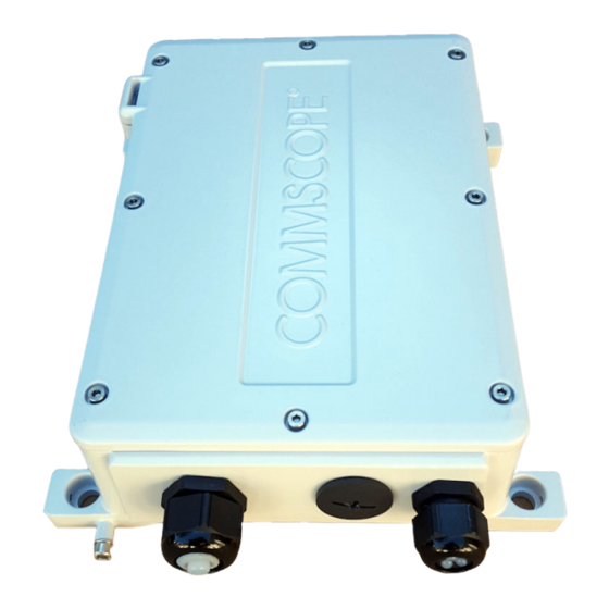
- Page 1 1-Port 5Gb PoE Extender Manual 860659348 Rev A October 2020 860659348 Rev A...
-
Page 3: Table Of Contents
Wall Mount ......................17 Pole Mount ......................18 Step 8: Grounding......................19 Step 9: Install the Solar Shield..................19 5 Detailed Specifications............... 21 Copyright, Trademarks and Commercial Disclaimer ............ 23 This product is copyright © 2020 CommScope, LLC. All Rights Reserved. - Page 4 1-Port 5Gb PoE Extender Manual This product is copyright © 2020 CommScope, LLC. All Rights Reserved.
-
Page 5: Notices
1-Port 5Gb PoE Extender Manual 1. Notices In support of Low Voltage Directive 2014/35/EU this notice contains safety information important for the correct installation and operation of this equipment. Note, the term SELV (Safety Extra Low Voltage) used in this addendum is defined strictly in accordance with IEC 62368-1. - Page 6 1-Port 5Gb PoE Extender Manual...
-
Page 7: Ce Notice
Cet appareil numerique de la class A est conforme a la norme ICES-003 du Canada Return Product Procedure If the unit is found to be defective, please contact Technical Support via http://www.commscope.com/SupportCenter WEEE Recycling information can be obtained from the Product Compliance Support Center at... - Page 8 1-Port 5Gb PoE Extender Manual...
-
Page 9: Introduction
1-Port 5Gb PoE Extender Manual 2. Introduction The 60W 5Gb 1-port PoE Extender is a component of CommScope's® powered fiber cable system, a hybrid optical fiber/copper cable system for remote powering of network access devices. It is designed to simply and easily function with the powered fiber cable system to extend the distance of PoE (Power over Ethernet) enabled devices. -
Page 10: Extender Surge Protection
1-Port 5Gb PoE Extender Manual Extender Surge Protection Long length DC low voltage electrical systems are at increased risk of: Noise from high voltage cables • Higher current in the event of a short circuit • Strong electrical surges due to lightning strikes or other EM events in close vicinity •... -
Page 11: Package Contents
16 AWG or 1.2mm wire diameter stripper for the 16 AWG cable • Fastenings for wall or pole mounting • Fiber splice kit and LC connectors or fiber patch cords. CommScope 760243403 | • QWIK-FUSE™ Installer Termination Toolkit recommended. Outdoor rated Cat6 or 6a shielded copper patch cord. CommScope CO11152-01 | •... - Page 12 1-Port 5Gb PoE Extender Manual...
-
Page 13: Installation
1-Port 5Gb PoE Extender Manual 4. Installation Installation of the PoE Extender should be completed in the following order. Step 1: Remove Solar Shield Remove the 4 bolts attaching the solar shield to the PoE Extender with a 3mm Allen key. Slide the solar shield off the retaining lugs and put to one side. - Page 14 1-Port 5Gb PoE Extender Manual...
-
Page 15: Step 3: Remove The Enclosure Lid
This may be cut and removed if desired. Step 4: Powered Fiber Cable Installation The CommScope Powered Fiber Cable consists of 2 insulated copper power conductors and a central tube containing the optical fiber. Separate the three cores to allow the power to be connected to the screw terminals, and the fiber thread to be connected to a fiber terminal, which is then inserted into the SFP. -
Page 16: Step 4B: Installing The Cable Gland
1-Port 5Gb PoE Extender Manual Ensure the separated segments are smooth to prevent water ingress issues through the grommet. Step 4B: Installing the Cable Gland Use tape or heat shrink to prevent the cables splitting further than the required length Thread the strands through the cap, then through the supplied grommet;... -
Page 17: Step 4C: Connecting The Power Strands
1-Port 5Gb PoE Extender Manual Step 4C: Connecting the Power Strands Cut the two power strands to length. For the 12 AWG cable, use a proper 12 AWG or 2MM diameter wire stripper. For the 16AWG, use a 16 AWG or 1.2mm wire diameter stripper. Note: The wires maybe connected in either polarity. - Page 18 1-Port 5Gb PoE Extender Manual Step 5: Ethernet Cable Installation A Cat6 or better shielded patch cord is recommended for the PoE connection. Thread the seal cap and grommet on to the cable as shown below. If using a pre-terminated Ethernet cable, it may be necessary to remove the boot. Note: With the latch facing up, insert the RJ45 plug through the the cable gland fitting and into the jack.
- Page 19 1-Port 5Gb PoE Extender Manual Using a torque wrench, tighten the screw cap onto the gland fitting. Tighten to 4 N-m (35in-lbf). ATTENTION: TO PREVENT MOISTURE AND DUST FROM ENTERING THE UNIT, ALL UNUSED PORTS SHOULD HAVE PLUGS INSTALLED AT ALL TIMES. *FAILURE TO DO SO COULD RESULT IN UNIT FAILURE*...
-
Page 20: Step 6: Sealing The Unit
1-Port 5Gb PoE Extender Manual Step 6: Sealing the Unit Ensure the supplied gasket is properly seated in its channel (it only fits in one orientation) and that all cables are secured. Apply Loctite 222 to all lid bolts. Put the lid back in place. Tighten the screws to torque 2.5Nm (22.1 in-lb). -
Page 21: Step 7: Mounting The Unit
1-Port 5Gb PoE Extender Manual Step 7: Mounting the Unit When vertically mounted, the extender must be installed with the cable ports facing downward. Wall Mount The PoE extender has 4 holes on the exterior of the device for attaching to a wall or flat surface... -
Page 22: Pole Mount
1-Port 5Gb PoE Extender Manual Pole Mount The four slots in the raised sections on the bottom of the device may be used for pole attachment using band clamps (jubilee clips). PoE pole mounted with solar shield... -
Page 23: Step 8: Grounding
1-Port 5Gb PoE Extender Manual Step 8: Grounding To ensure protection from lightning strikes and other electrical surges, the PoE extender must be earthed. Any end device connected to the PoE extender must also be bonded to earth. Make connections from the enclosure earth point using the M5 bolt and washer provided: A minimum 16AWG bonding connection from the Customer’s equipment earth terminal to a reliable earth (ground) point. - Page 24 1-Port 5Gb PoE Extender Manual...
-
Page 25: Detailed Specifications
1-Port 5Gb PoE Extender Manual 5. Detailed Specifications Table 4.4 and provides a partial listing of the maximum supported hybrid cable distances for a range of NEC Class 2 power supply output voltages, hybrid cable copper gauges, and extender output power levels. NEC Class 2 requires a power supply unit (PSU) limited to less than 60V DC. In practice, some commercial 48V power supplies may be configured to output from 48V up to about 57V. - Page 26 1-Port 5Gb PoE Extender Manual Table 4.4: Physical Dimensions Item Specification Dimensions including solar shield 283mm x 225mm x 77mm Weight 3.8kg Note: Not intended for submerged installation. Table 4.5: EMI/C, & Safety and Regulatory Item Specification EMC Emissions Class A limits USA: FCC CFR 47 Part 2 / Part 15 Subpart B Canada:...
-
Page 27: Copyright, Trademarks And Commercial Disclaimer
5GBASE-T/2.5GBASE-T/1000BASE-T/100BASE-TX/10BASE-Te Copyright, Trademarks and Commercial Disclaimer To find out more about CommScope® products, visit us on the web at www.commscope.com All trademarks identified by ® or ™ are registered trademarks or trademarks, respectively, of CommScope, Inc. © 2020 Commscope, Inc All Rights Reserved This product is covered by one or more U.S.
Need help?
Do you have a question about the PFU-P-E-O-060-01 and is the answer not in the manual?
Questions and answers