Advertisement
Table of Contents
- 1 Ultranexus-Sdi Rear Panel
- 2 Ultranexus-Sdi Audio Inputs/Outputs
- 3 Ultranexus-Sdi Rear Panel Connectors
- 4 Ultranexus-Sdi Configuration Without an External Switcher
- 5 Ultranexus-Sdi Configuration with an External Switcher
- 6 Network Ethernet Connection
- 7 Entering Tcp/Ip Addresses into Ultranexus-Sdi Front Panel
- 8 Direct Ethernet Connection
- Download this manual
LEIGHTRONIX, INC.
Video Servers
Television Automation
●
2011-06-20
Refer to the labeled "UltraNEXUS-SDI Rear Panel" illustration below while installing your
NOTES
server/controller.
For additional information on LEIGHTRONIX-approved USB hard drives and VCRs/DVD
players compatible with the IR ports, contact LEIGHTRONIX.
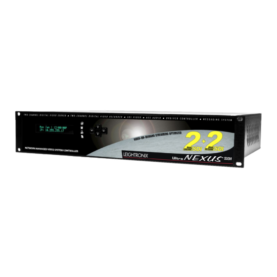
ULTRANEXUS-SDI REAR PANEL
ULTRANEXUS-SDI REAR PANEL CONNECTORS
A
* IR Ports: using the supplied IR transmitter cables,
connect up to four, LEIGHTRONIX-approved VCRs and/
or DVD players
B
* DVply Ports: connect up to two, supported devices with
title:chapter access
C
* "COM 1": connect a switcher with inputs/outputs of up
to 250x250
"COM 2": if using, connect a LEITCH CSD-5300 or ESE
Master Clock time source
D
* "PRO-BUS" Port: attach up to 16 PRO-BUS device
interfaces in a daisy chain to the PRO-BUS jack and
connect each interface to the corresponding VCRs and/or
DVD players. Perform the following steps (see PRO-BUS
Manuals for more information):
1. Set each PRO-BUS interface's dip switches to
assign each interface an address #. Number the
interfaces consecutively, starting with "01" at the
interface connected to the UltraNEXUS-SDI.
2. Set control mode dip switches on each interface.
3. If possible, ensure each device's switcher input
numbers correspond to its PRO-BUS address #.
4. Document your PRO-BUS/device setup.
* Only available for use when UltraNEXUS-SDI is connected to an external switcher.
E
MPEG Player 1 Video Output
F
Broadcast Recorder Video Input
G
MPEG Player 2 Video Output
H
VOD Recorder Video Input
I
Ethernet Port 1: connect a straight-through or cross-over
cable (see page 4 of this document)
Ethernet Port 2: reserved for the LEIGHTRONIX TOTAL
SHARE™ network option
J
USB Drive Ports: connect up to four, LEIGHTRONIX-
approved USB drives
LEIGHTRONIX requires the use of 2 USB drives
NOTES
when the UltraNEXUS-SDI is combined with a
LEIGHTRONIX streaming VOD service.
Remove/install USB drives only after shutting down
the UltraNEXUS-SDI its front panel. Do not connect
the drives to a PC for file management operations.
O
Power Cord Connector
UltraNEXUS-SDI INSTALLATION QUICK GUIDE
ULTRANEXUS-SDI AUDIO INPUTS/OUTPUTS
The UltraNEXUS-SDI supports embedded AES (SMPTE 272M) audio signals as well as non-embedded
AES (IEC 60958 type 1 balanced) and balanced, two-channel analog audio. To wire your system for non-
embedded audio, use the four audio terminal blocks on the rear panel, represented as follows:
K
M
MPEG Player 1 Audio Output
VOD Recorder Audio Input
L
N
Broadcast Recorder Audio Input
MPEG Player 2 Audio Output
Applicable to each terminal block, connect your non-embedded AES and analog audio signal wiring
according to the diagrams below.
AES3 Wiring Diagram
2-Channel Analog Wiring Diagram
Rack mount your UltraNEXUS-
START
SDI, ensuring the ventilation
holes are not covered.
NOTES
An optional bracket kit is available for supporting
the back of a rack-mounted UltraNEXUS-SDI
(contact LEIGHTRONIX for more details).
LEIGHTRONIX recommends leaving empty rack
positions above and below the UltraNEXUS-SDI.
Are you using an external switcher
with your UltraNEXUS-SDI?
Yes: Continue steps on
page 3 of this document.
PAGE 1
No: Continue steps on
page 2 of this document.
PAG
E 1
Advertisement
Table of Contents

Related Manuals for Leightronix UltraNEXUS-SDI


Summary of Contents for Leightronix UltraNEXUS-SDI
- Page 1 ULTRANEXUS-SDI REAR PANEL ULTRANEXUS-SDI AUDIO INPUTS/OUTPUTS The UltraNEXUS-SDI supports embedded AES (SMPTE 272M) audio signals as well as non-embedded AES (IEC 60958 type 1 balanced) and balanced, two-channel analog audio. To wire your system for non- embedded audio, use the four audio terminal blocks on the rear panel, represented as follows:...
- Page 2 Continue steps on 5300 or ESE Master Clock time Connect your USB hard drive(s) to connector on the rear panel of the UltraNEXUS-SDI simultaneously pressing the right and left source to the “COM 2” port (C) on the UltraNEXUS-SDI rear panel (J).
- Page 3 5300 or ESE Master Clock time Connect your USB hard drive(s) to Continue steps on connector on the rear panel of the UltraNEXUS-SDI simultaneously pressing the right and left source to the “COM 2” port (C) on the UltraNEXUS-SDI rear panel (J).
- Page 4 Subnet mask: your PC’s subnet mask address IP address: “Edit unit IP Address” screen 4. Using a cross-over RJ-45 Ethernet cable, connect the UltraNEXUS-SDI Ethernet Port 1 (I) to the PC’s NIC. Subnet mask address: “Edit unit Subnet Mask” screen Gateway address: “Edit unit Gateway Addr”...
Need help?
Do you have a question about the UltraNEXUS-SDI and is the answer not in the manual?
Questions and answers