
Related Manuals for Yamaha EF5500DE


Summary of Contents for Yamaha EF5500DE
- Page 1 Generator OWNER’S MANUAL Read this manual carefully before operating your Yamaha generator. EF5500DE EF5500D LIT-19626-02-82 7P5-F8199-14...
- Page 2 Read this manual carefully before operating your Yamaha generator. This manual should stay with this generator if it is sold.
- Page 3 INTRODUCTION Congratulations on your purchase of your new Yamaha Generator. This manual will provide you with a good basic understanding of the operation and maintenance of this generator. If you have any questions regarding the operation or maintenance of your generator, please consult a Yamaha dealer.
- Page 4 OPERATING THE GENERATOR. A WARNING indicates a hazardous sit- uation which, if not avoided, could result in death or serious injury. 9 Yamaha continually seeks advance- NOTICE ments in product design and quality. Therefore, while this manual contains A NOTICE indicates special precau-...
-
Page 5: Table Of Contents
(For EF5500DE) ....... 48 LABELS ..........6 Fuse Replacement DESCRIPTION ........7 (For EF5500DE) ....... 49 Control Panel (For EF5500DE) ..8 G.F.C.I. Receptacle Test ....50 Control Panel (For EF5500D) ..... 8 STORAGE ........... 51 CONTROL FUNCTION ......9 Drain The Fuel ........ -
Page 6: Safety Information
SAFETY INFORMATION 9 This generator is not designed for on-board use. Do not use it while installed on the vehicle. 9 Do not modify the generator or use it with its parts removed. 9 Do not allow children to operate the generator. 9 Do not place any obstacles on the generator. -
Page 7: Carbon Monoxide Poisoning
Carbon Monoxide Poisoning 9 CO gas is toxic and can cause serious injury or death. 9 Get fresh air and seek medical care immediately, if you are suspected to be inhaled carbon monoxide. 9 Early symptoms of carbon monoxide exposure include headache, fatigue, shortness of breath, nausea, and dizziness and so on. -
Page 8: Fuel Is Highly Flammable And Poisonous
Fuel is Highly Flammable and Poisonous 9 Always turn off the engine when refuelling. 9 Never refuel while smoking or in the vicinity of an open flame. 9 Take care not to spill any fuel on the engine or muffler when refuelling. 9 Do not leave the generator inside the vehicle or in the trunk. -
Page 9: Electric Shock Prevention
Electric Shock Prevention 9 Never operate the engine in rain or snow. 9 Never touch the generator with wet hands or elec- trical shock will occur. 9 When the connected electric device is grounded (earthed), always ground (earth) the generator. 9 Connect the ground (earth) terminal to a ground source. -
Page 10: Connection Notes
Connection Notes 9 Avoid connecting the generator to commercial power outlet. 9 Avoid connecting the generator in parallel with any other generator. 1 Correct 2 Incorrect Connection WARNING Before the generator can be connected to a build- ing’s electrical system, a licensed electrician must install an isolation (transfer) switch in the build- ing’s main fuse box. -
Page 11: Location Of Important Labels
LOCATION OF IMPORTANT LABELS Please read the following labels carefully before oper- ating this generator. Maintain or replace safety and instruction labels, as necessary. DISPLACEMENT : O I L DANGER Using a generator indoors CAN KILL YOU IN MINUTES. Generator exhaust contains carbon monoxide. This is a poison you cannot see or smell. -
Page 12: Description
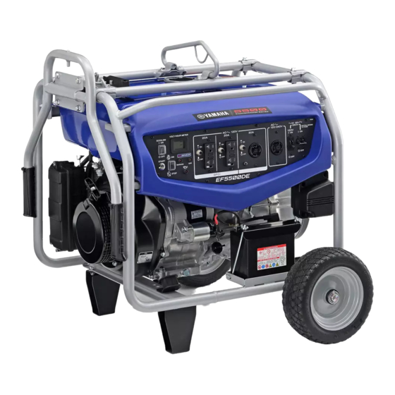
1 Carrying handles (shaded) 2 Fuel tank cap 3 Fuel level gauge 4 Fuel tank 5 Ground (earth) terminal 6 Battery (For EF5500DE) 7 Oil filler cap 8 Oil drain bolt 9 Spark plug 0 Fuel cock q Recoil starter handle... -
Page 13: Control Panel (For Ef5500De)
Control Panel EF5500DE (For EF5500DE) 1 Starter switch 2 Economy control switch 3 Engine switch 4 Voltage/hour meter 5 G.F.C.I. receptacle 6 AC receptacle 7 AC switch (N.F.B.) 8 ERR (Error) indicator light (Orange) 9 Oil warning light (Red) 0 WARNING indicator... -
Page 14: Control Function
If the engine stalls or does not start, turn the engine switch to “7” (ON) and then push the starter switch (for EF5500DE) or pull the recoil starter. If the oil warn- ing light flickers for a few seconds, the engine oil is insufficient. -
Page 15: Co Sensor
CO SENSOR The CO SENSOR is a system that automatically stops the engine before the surrounding CO concentration exceeds a certain level. WARNING 9 Do not remove or modify the CO SENSOR sys- tem. 9 The CO SENSOR cannot prevent all danger associated with or caused by carbon monox- ide. - Page 16 If the engine is stopped by the CO SENSOR system, change the operating location of the generator to well- ventilated area. 9 Place the generator so that the muffler is pointed in the same direction as the wind is blowing, and the exhaust gas is directed away from buildings, other structures, or vehicles.
- Page 17 California legislature. When you discard the lithium battery in California, USA, please follow the related regulations in advance. Perchlorate material-special handling may apply, see www.dtsc.ca.gov/hazardouswaste/perchlorate 9 Consult a Yamaha dealer for the CO SENSOR replacement. – 12 –...
- Page 18 WARNING 9 If the indicator lights do not flash 5 times upon starting, discontinue generator use immediate- ly and consult a Yamaha dealer. The CO SENSOR system may be malfunctioning. 9 If the CO SENSOR WARNING indicator light (red) is flashing, immediately clear the area of all people and animals while moving the gen- erator to an open, outdoor area.
-
Page 19: Ac Switch (N.f.b.)
∫ Supplies AC 120 V and 240 V NOTICE Reduce the load to the specified generator rated output if the AC switch (N.F.B.) turns off. If it turns off again, consult a Yamaha dealer. Fuel Tank Cap Remove the fuel tank cap by turning it counterclock- wise. -
Page 20: Ground (Earth) Terminal
Ground (Earth) Terminal Ground (earth) terminal connects the earth line for prevention of electric shock. When the electric device is earthed, always the gener- ator must be earthed. 1 Ground (earth) terminal Economy Control Switch 1 “I” (ON) When the economy control switch is turned to “I” (ON), the economy control unit controls the engine speed according to the connected load. -
Page 21: Recoil Starter
9 Do not touch the recoil starter handle while the generator is operating. Starter Switch (For EF5500DE) The starter switch controls the following item. Push: Starting circuit is switched on. -
Page 22: G.f.c.i. Receptacle
G.F.C.I. Receptacle WARNING TO REDUCE THE CHANCE OF ELECTRICAL SHOCK: 9 Do not attempt to operate electric devices if the ground fault circuit interrupter reset button 000-000 pops out repeatedly during use. 9 Test the ground fault circuit interrupter during the pre-operation checks according to the maintenance instructions on page 50. -
Page 23: Preparation
PREPARATION Two Wheel Kit Installation 1. Fasten the engine hanger to the carrier frame with the bolts. Match the punch marks as shown in the illustration. 000-000 1 Bolt (8 × 16 mm Flange bolt) 2 Engine hanger 3 Carrier frame Tightening torque: 16 N·m (1.6 kgf·m, 12 lb·ft) 000-000... - Page 24 3. Insert the bolt into the carrier frame, and then put the washer, collar, and lock lever in this order, and tighten the nut. 9 Make sure that the collar is placed into the washer. 9 Lock lever pin should be above stopper. 000-000 8 Nut (8 mm Flange nut [Self-locking nut]) 9 Lock lever...
- Page 25 5. Install the sleeve on the generator frame. Refer to the illustration to be sure that the sleeve is installed properly. y Sleeve 000-000 u Generator frame 6. Install the bracket handle to the sleeve. i Bracket handle 000-000 7. Install the locating damper on the sleeve. o Locating damper 000-000 8.
- Page 26 10. Lift the generator 20 cm (7.87 in) off the ground using a winch or other suitable lifting device. 11. Fasten the main stand to the left side of the gener- ator frame as viewed when looking at the control panel with the bolts and nuts.
- Page 27 13. Install the washers into wheel axle. 14. Insert cotter pins into wheel axle frame, and then bend as shown in the illustration. h Wheel j Washer k Cotter pin 15. Fasten the wheel axle frame to the generator frame with the bolts and nuts. Make sure that the wheel axle frame is on the right side of the control panel.
-
Page 28: Fuel
Fuel WARNING 9 Fuel is highly flammable and poisonous. Check “SAFETY INFORMATION” (See page 3) carefully before filling. 9 Do not overfill the fuel tank, otherwise it may overflow when the fuel warms up and expands. 9 Wipe up any spilled fuel immediately. 9 Never refuel while smoking or in the vicinity of an open flame. - Page 29 7DK-093 Total: 26 L (6.87 US gal, 5.72 Imp gal) Your Yamaha engine has been designed to use regu- lar unleaded gasoline with a pump octane number ((R + M)/2) of 86 or higher, or research octane number of 91 or higher.
-
Page 30: Engine Oil
Engine Oil Make sure the engine oil is at the correct level of the oil filler hole. 1 Oil filler cap 2 Correct level Recommended engine oil: Recommended oil brand: YAMALUBE Available oil grade: API SE type or higher JASO MA or MB Available viscosity index: 10W-30 or 10W-40 700-110a... -
Page 31: Battery (For Ef5500De)
Battery (For EF5500DE) (See page 48 for more details) This generator is designed to be equipped with a VRLA (Valve Regulated Lead Acid) battery. There is no need to check the electrolyte or to add distilled water. Installation 1. Turn the engine switch to “5” (STOP) to prevent accidental short circuiting. -
Page 32: Ground (Earth) Terminal
5. Connect the negative lead (Black) to the negative (–) battery terminal. 9 Screw 0 Negative lead (Black) q Negative battery terminal Connect the positive lead (Red) to the positive (+) bat- tery terminal first, then the negative lead (Black) to the negative (–) battery terminal. -
Page 33: Pre-Operation Check
9 Check oil level in engine. 9 If necessary, add recommended oil to specified level. 9 Check generator for oil leakage. Abnormal Running Conditions 9 If any abnormal running conditions are observed, please consult a Yamaha dealer. – 28 –... -
Page 34: Operation
OPERATION WARNING 9 Never operate the engine in a closed area or it may cause unconsciousness and death within a short time. Operate the engine in a well ven- tilated area. 9 Before starting the engine, do not connect any electric devices. - Page 35 4. Turn the choke lever to “1”. 4 Choke lever The choke is not required to start a warm engine. Turn the choke lever to the original position. Electric Starting (For EF5500DE): 5. Push the starter switch to start the engine. 5 Starter switch NOTICE 9 Take your hand off the switch immediately after the engine starts.
- Page 36 Manual Starting: 5. Grasp the recoil starter handle and pull slowly until resistance is felt. Give the starter handle and rope a short, brisk pull to start the engine. WARNING Be careful when using recoil starter. In rare cases, the recoil starter handle can be drawn back quickly by the engine kickback.
-
Page 37: Stopping The Engine
NOTICE If either of them does not flash, consult a Yamaha dealer since the CO SENSOR system is most likely malfunctioning. 7. After the engine starts, warm up the engine until the engine does not stop when the choke lever is returned to the original position. - Page 38 3. Disconnect any electric devices. 4. Turn the engine switch to “5” (STOP). 2 “5” (STOP) 5. Turn the fuel cock lever to OFF. 3 OFF 705-038d – 33 –...
-
Page 39: Connection
Connection Alternating Current (AC) WARNING Be sure any electric devices are turned off before plugging them in. NOTICE 9 Be sure all electric devices including the lines and plug connections are in good condition before connection to the generator. 9 Be sure the total load is within generator rated output. - Page 40 NOTICE Reduce the load to the specified generator rated output if the AC switch (N.F.B.) turns off. If it turns off again, consult a Yamaha dealer. 9 The 4-blade plug receptacle can supply both 240V 120 V and 240 V power sources.
-
Page 41: Application Range
Application Range When using the generator, make sure the total load is within rated output of a generator. Otherwise, generator damage may occur. 0.4–0.75 Power factor 0.8–0.95 (Efficiency 0.85) –4500 W –3600 W –1530 W Approximate Wattages of Common Tools or Equipment Tools Wattage Equipment... -
Page 42: High Altitude Operation
4000 ft. (1219 meters). If you operate your engine at altitudes above 4000 ft. (1219 meters) consistently, have your local Yamaha dealer perform the neces- sary carburetor modification. This engine should be operated in its original configuration below 4000 ft. -
Page 43: Periodic Maintenance
WARNING If you are not familiar with maintenance work, have a Yamaha dealer do it for you. Maintenance Chart WARNING Stop the engine before starting maintenance work. - Page 44 *2····· The air filter element needs to be replaced more frequently when using in unusually wet or dusty areas. ····· Since these items require special tools, data and technical skills, have a Yamaha dealer per- form the service. – 39 –...
-
Page 45: Carburetor Adjustment
Carburetor Adjustment The carburetor is a vital part of the engine. Adjusting should be left to a Yamaha dealer with the professional knowledge, specialized data, and equipment to do so properly. Spark Plug Inspection The spark plug is important engine components, which should be checked periodically. -
Page 46: Engine Oil Replacement
Engine Oil Replacement WARNING Avoid draining the engine oil immediately after stopping the engine. The oil is hot and should be handled with care to avoid burns. 1. Place the generator on a level surface and warm up the engine for several minutes. Then stop the engine. - Page 47 6. Add engine oil to the correct level. NOTICE Be sure no foreign material enters the crankcase. 5 Correct level 700-006a Recommended engine oil: Recommended oil brand: YAMALUBE Available oil grade: API SE type or higher JASO MA or MB Available viscosity index: 10W-30 or 10W-40 Engine oil quantity:...
-
Page 48: Muffler Screen And Spark Arrester
Muffler Screen and Spark Arrester WARNING The engine and muffler will be very hot after the engine has been run. Avoid touching the engine and muffler while they are still hot with any part of your body or clothing during inspection or repair. 1. - Page 49 5. Remove the carbon deposits on the muffler screen and spark arrester using a wire brush. NOTICE When cleaning, use the wire brush lightly to avoid damaging or scratching of the muffler screen and 711-022 spark arrester. 6. Check the muffler screen and spark arrester. Replace them if damaged.
-
Page 50: Air Filter
Air Filter 1. Remove the screws, and then remove the air filter case cover. 2. Remove the foam element. 1 Screw 2 Air filter case cover 3 Foam element 3. Wash the foam element in white kerosene and dry WARNING Never use white kerosene while smoking or in the vicinity of an open flame. -
Page 51: Fuel Cock
Fuel Cock WARNING Never use the gasoline while smoking or in the vicinity of an open flame. 1. Stop the engine. 2. Turn the fuel cock lever to OFF. 3. Remove the fuel cock cup, gasket and fuel strain- 4. Clean the cup and fuel strainer with gasoline and wipe it off. -
Page 52: Fuel Tank Filter
Fuel Tank Filter WARNING Never use the gasoline while smoking or in the vicinity of an open flame. 1. Remove the fuel tank cap and fuel tank filter. 1 Fuel tank cap 2 Fuel tank filter 2. Clean the fuel tank filter with gasoline. Replace it if damaged. -
Page 53: Battery (For Ef5500De)
VRLA (Valve Regulated Lead Acid) battery. There is no need to check the electrolyte or to add distilled water. To Charge The Battery Have a Yamaha dealer charge the battery as soon as possible if it seems to have discharged. NOTICE To charge a VRLA battery, a special (constant-volt- age) battery charger is required. -
Page 54: Fuse Replacement (For Ef5500De)
1. Remove the control panel screws and then remove the control panel. 1 Control panel screw 2. Replace the blown fuse with one of proper amper- age. Specified fuse: 20 A If the fuse immediately blows again, consult a Yamaha dealer. – 49 –... -
Page 55: G.f.c.i. Receptacle Test
Incorrect 4. If G.F.C.I. operation is correct, push in the reset button. If the G.F.C.I. operates incorrectly, consult a Yamaha dealer. 763-059 WARNING Do not operate the generator with a faulty G.F.C.I. circuit. Electric shock could occur. Have the gener- ator repaired by a qualified mechanic. -
Page 56: Storage
STORAGE Long term storage of your generator will require some preventive procedures to guard against deterioration. Drain The Fuel 1. Turn the engine switch to “5” (STOP). 1 “5” (STOP) 2. Remove the fuel tank cap and fuel tank filter. Extract the fuel from the fuel tank into an approved gasoline container using a commercially available hand siphon. - Page 57 6. Drain the fuel remaining in the carburetor into an approved container by loosening the drain screw on the carburetor float chamber. 4 Drain screw 7. Tighten the drain screw. 8. Turn the engine switch to “5” (STOP). 9. Turn the fuel cock lever to OFF. 10.
-
Page 58: Engine
Engine Perform the following steps to protect the cylinder, pis- ton ring, etc. from corrosion. 1. Remove the spark plug, pour about one table- spoon of engine oil (See page 42) into the spark plug hole and reinstall the spark plug only. Recoil start the engine by turning over several times (with ignition off) to coat the cylinder walls with oil. -
Page 59: Battery (For Ef5500De)
Battery (For EF5500DE) 1. Remove the battery. 2. Store the battery in a cool, dark and dry place and charge it once a month. Do not store the battery in an excessively warm or cold place [i.e., less than 0 °C (32 °F) or more than 30 °C (86 °F)]. -
Page 60: Troubleshooting
Poor spark 2 Spark plug dirty with carbon or wet ..Remove carbon or wipe spark plug dry. 2 Faulty ignition system ..Consult a Yamaha deal- 791-001d Generator Won’t Produce Power 2 Safety device (AC switch) to “3” (OFF) ..Turn the AC switch (N.F.B.) to “I”... - Page 61 CO SENSOR Indicator Lights flash or come on abnormally If the generator shows any of the following conditions upon starting or during operation, consider your own safety, stop the generator, and then please consult a Yamaha dealer. Status Check Engine Upon starting, both the “CO...
- Page 62 9 To prevent ELECTRIC SHOCK do not hold spark plug lead with hand while testing. Does not spark Check the following. Clean or Clogged 9 Fuel line clogging replace. Engine does not start. 9 Air filter element clogging Consult a Yamaha dealer. – 57 –...
- Page 63 Faulty battery and/or starter motor. Consult a Yamaha dealer. Check engine oil level. Level low Consult a Add engine oil. Yamaha dealer. Check the spark plug. 9 Type: BPR4ES (NGK) 9 Gap: 0.7–0.8 mm (0.028–0.031 in) Incorrect Clean the spark Replace or adjust gap.
- Page 64 Clean the spark Replace or while testing. adjust gap. plug. Does not spark Clean or Check the following. Clogged replace. Engine does not start. 9 Fuel line clogging 9 Air filter element clogging Consult a Yamaha dealer. – 59 –...
-
Page 65: Specifications
SPECIFICATIONS Dimensions Unit EF5500DE EF5500D Overall length (*1) mm (in) 740 (29.1) 740 (29.1) Overall length (*2) mm (in) 1070 (42.1) 1070 (42.1) Overall width mm (in) 736 (29.0) 736 (29.0) Overall height mm (in) 800 (31.5) 800 (31.5) Dry weight kg (lb) 108 (238.1) -
Page 66: Consumer Information
PRI-I.D. NUMBER: Record your Primary I.D., and serial num- bers in the spaces provided, to assist you MODEL in ordering spare parts from a Yamaha dealer. PRI-I.D. Also record and keep these I.D. numbers in a separate place in case your generator CODE SERIAL No. -
Page 67: Exhaust Emission Control System And Components
ROAD ENGINES. The acronyms conform to the latest version of the SAE’s recommended practice docu- ment J1930, “Diagnostic Acronyms, Terms, and Definitions For Electrical/Electronic System”. It is recommended that these items be serviced by a Yamaha dealer. – 62 –... -
Page 68: Wiring Diagram
WIRING DIAGRAM EF5500DE R R/W B/W O Br P G/Y Color code 1 Rotor assembly o Economy control switch Black 2 Sub coil p Starter relay Brown 3 Main coil a Starter motor Green 4 Stator assembly s Carburetor solenoid valve... -
Page 69: Ef5500D
EF5500D B L/R Br P G/Y Color code 1 Rotor assembly w Oil warning unit Black 2 Sub coil e Oil warning light Brown 3 Main coil r Economy control unit Green 4 Stator assembly t Solenoid valve Blue 5 Voltage/hour meter y Economy control switch Orange 6 AC switch (N.F.B.) -
Page 70: Yamaha Extended Service (Y.e.s.)
9 Y.E.S. is flexible. You can choose the plan that’s right for you: 12 months, 24 months or 36 months coverage. 9 Y.E.S. is administered by the same Yamaha people that handle your warranty - and it shows in the comprehensive coverage benefits. There are no hour limitations and Y.E.S. covers manufacturing defects just like your warranty. - Page 72 PRINTED IN CHINA 2021.06×1 !
Need help?
Do you have a question about the EF5500DE and is the answer not in the manual?
Questions and answers
where is the co sensor on the EF5500DE? The unit I have when I switch from high idle to low idle stalls out.? what would be a good place to start trouble shooting?