
Related Manuals for HYPERVSN MS


Summary of Contents for HYPERVSN MS
- Page 1 See extraordinary OPERATING MANUAL Integrated 3D Holographic Display System © Copyright 2020 HYPERVSN. All rights reserved...
-
Page 2: Table Of Contents
9. TECHNICAL MAINTENANCE ............33 10. SAFETY PROVISIONS ................ 35 11. MAINTENANCE, WARRANTY AND DISPOSAL ......37 11.1 MAINTENANCE ................ 37 11.2 WARRANTY ................37 11.3 DISPOSAL ................... 37 12. SPECIAL REQUIREMENTS ............... 38 M20MS11 © Copyright 2020 HYPERVSN. All rights reserved... - Page 3 WARNING. This Operating Manual must be thoroughly read and understood before installation, operation and use of HYPERVSN Device. This Operating Manual is designed as a general guide for HYPERVSN Models MS and MS-L (hereinafter referred to as, the “Device”). This Operating Manual provides an overview, safety rules and requirements, technical specifications and other important information required to assemble, install and operate the Device.
-
Page 4: Device Overview
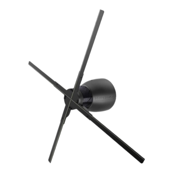
The Device’s spinning rays create a surface on which 3D video content can be displayed. • The Device displays holographic visuals up to 56 cm in size (model MS - with 56 cm rays) or up to 75 cm in size (model MS-L - with 75 cm rays). •... - Page 5 Picture 2. Key Device components and the remote control Configuration options Devices can be installed according to one of several specific patterns and synchronized. These multiple Devices working together form the HYPERVSN Wall, which allows for the display of a single, large 3D image. Picture 3. HYPERVSN Wall...
- Page 6 The Device (and the HYPERVSN Wall) can be equipped with the HYPERVSN MasterBox. It is an additional component that connects to the Device or the HYPERVSN Wall to provide additional functionality (including possibility of synchronized sound reproduction when the audio facilities are connected to).
-
Page 7: Technical Specifications
Noise figure on the Device 45 Db 50 Db axis (1m from the Device) ceramic 4A 250VAC ceramic 4A 250VAC Fuse 5X20 mm 5X20 mm Power cable length Power cable thickness 8 mm (max) 8 mm (max) © Copyright 2020 HYPERVSN. All rights reserved... - Page 8 (at temperature 25°C+, humidity 50%. MIL-HDBK-217F method is utilized) Important. The HYPERVSN Wall can only be formed with Model MS. Model MS-L is not compatible with the HYPERVSN Wall. We are not able to guarantee proper operation and functionality of the HYPERVSN Wall, should Model MS-L be used.
-
Page 9: Package Contents
This set of tools and fittings listed above are intended for the mounting of the Device onto the wall bracket supplied with the Device. In the event that the Device will be installed with another HYPERVSN accessory, see the Operating Manual for these instructions. -
Page 10: Device Installation Areas
WARNING. The Device must remain at a safe distance from viewers. Do not install the Device in areas affected by high temperatures, heavy steam/vapor, large volumes of dust, air conditioners, radiators, ovens and other similar equipment. Ensure that the Device is properly ventilated. © Copyright 2020 HYPERVSN. All rights reserved... -
Page 11: Installation Recommendations
5 m high it is recommended to install at least three Devices side by side. Where possible, have the rays exceed the installation surface to showcase the transparent nature of the Devices’ displays. The recommended Device installation angle is 90° to the mounting surface. © Copyright 2020 HYPERVSN. All rights reserved... -
Page 12: Device Assembly
Contact your supplier if you notice any irregularities during the visual check. Device assembly procedure Attention. If the Device is supplied with the rays pre-assembled, skip step 1-3 of the procedure described in this section. © Copyright 2020 HYPERVSN. All rights reserved... - Page 13 Do not tighten the M2,5x5 screws too much, to avoid deforming the rays. Push the switch on the stator to the right, if you would prefer to control the Device without the remote control. RIGHT POSITION Picture 8. Position of the switch © Copyright 2020 HYPERVSN. All rights reserved...
-
Page 14: Device Installation
Note. The following procedure describes the installation of the Device with the HYPERVSN wall bracket (supplied with the Device). In the event that the Device will be installed with another HYPERVSN accessory, see the Operating Manual for the accessories for these instructions. - Page 15 Place the Device on the wall bracket and slide it firmly downwards (Picture 10, step 3). Attach the safety screw (supplied complete with the wall bracket) to the safety hole and screw it in, using a PH2 screwdriver (Picture 10, step 4). © Copyright 2020 HYPERVSN. All rights reserved...
-
Page 16: Overview Of Device Operating Modes
Device or if media playback has stopped. Picture 12. Starting message in the Hotspot (Setup) mode Note. If you intend to use the HYPERVSN Solo Application to control the Device, switch the Device to Hotspot (Setup) mode. © Copyright 2020 HYPERVSN. All rights reserved... -
Page 17: Switching The Device On And Off
The Device must always be switched off and the rays completely • stationary before you change the Device operation mode (by moving the mode switches). Important. When moving the Device, do not hold onto the rays. If mishandled, they can be easily broken. © Copyright 2020 HYPERVSN. All rights reserved... -
Page 18: Status Indicators Of The Device
7.3 STATUS INDICATORS OF THE DEVICE The Device’s status can be determined based off of the activity displayed on the three indicators on the base of the stator. GREEN BLUE Picture 15. Device status indicators © Copyright 2020 HYPERVSN. All rights reserved... - Page 19 Attention. Only the rotor of model MS/MS-L must be used with the stator of model MS/MS-L (the rotor of models MS/MS-L has the “MS”/”MS-L” sticker located near the rotor serial number). 3. The Device is connected to the power mains without the rotor being properly attached to the stator.
-
Page 20: Cms Account Registration, Device Activation, Calibration
CMS software version. Upon purchase, each customer receives a personal email invitation. If you have not received this, kindly contact your dealer or HYPERVSN customer service. Click Set my password in the email invitation you received or open your browser and paste the specified link into the address bar. - Page 21 The next page will open: Picture 18. CMS account login page Enter your e-mail and password once again. Click Log In. Click My Company in the open page. Picture 19. Dashboard The next page will open: © Copyright 2020 HYPERVSN. All rights reserved...
- Page 22 (Picture 21). The following page will open: Picture 22. “My Profile” page Check the data. If it is required to be changed, click Edit profile and edit the data in the open window. © Copyright 2020 HYPERVSN. All rights reserved...
-
Page 23: Device Activation And Calibration
(you move the mode switch). Turn the Device on again. The Device will start to display the “HYPERVSN” logo. After a few seconds the “Activate your device” message will start to alternate on the Device with examples of videos. - Page 24 Connect to the “hypervsn-YYXXXXX” Wi-Fi network (YYXXXXX is a serial number located on the base of the rotor): use the following password: 0c3a71dad2. Note. The first digit in the password is a zero. Picture 25. Entering the password Note. Depending on the operating system, a message with a requirement to enter a code may appear at this step, ignore it and choose the command to enter the password.
- Page 25 To adjust the image’s horizontal orientation, click Right to rotate the image clockwise, and Left to rotate the image counter-clockwise. Turn the “Calibration screen” switch “Off” position. Click Next (Picture 28). Click Add Network in the open page: © Copyright 2020 HYPERVSN. All rights reserved...
- Page 26 In the open dialog window, enter the required information for the Wi-Fi network that you plan to use with the Device. Click Add Network. Picture 31. Adding Wi-Fi network information Any number of networks may be used. Picture 32. Step of the activation procedure © Copyright 2020 HYPERVSN. All rights reserved...
- Page 27 Login: example login example * * * * * login * * * * * Distance to the router: up to 3m. >3 m Wi-Fi frequency: 2.4GHz. 2.4 GHz 5.0 GHz © Copyright 2020 HYPERVSN. All rights reserved...
- Page 28 Click Activate (Picture 33). The next message will appear: Picture 34. Waiting for activation results Look at the Device. The Device will start the booting animation. Picture 35. Booting animation on the Device © Copyright 2020 HYPERVSN. All rights reserved...
- Page 29 Click Activate once again. If the message is still on the Device display, contact the Tech Support team at support@hypervsn.com. The activation is completed. When the activation is completed, switch the Device off. © Copyright 2020 HYPERVSN. All rights reserved...
- Page 30 Turn the mode switch on the rotor to Operating mode (Picture 11). Switch the Device on. The “HYPERVSN” message will appear (Picture 23) for several seconds. Then the starting animated message will appear and will be displayed constantly (Picture 13).
- Page 31 The Device has a default subscription activated. If you have purchased any upgraded subscription, alternative to the default one, click Activate subscription located near the Device serial number on the “My Devices” tab. © Copyright 2020 HYPERVSN. All rights reserved...
- Page 32 After all of these steps have been completed you will be able to create a media campaign and upload your content. Go to the Dashboard and select the suitable guides to receive detailed instructions on how to manage the Device and the CMS. Picture 43. HYPERVSN tutorials © Copyright 2020 HYPERVSN. All rights reserved...
-
Page 33: Technical Maintenance
In the event that the Device needs to be disassembled, take the following steps: Insert a PH2 screwdriver into the screw hole of the rotor. Unscrew the binding screw inside it (the binding screw is spring-loaded). © Copyright 2020 HYPERVSN. All rights reserved... - Page 34 • • Tighten the binding screw until it stops by turning it clockwise. Attention. If the assembly steps are performed correctly, there will not be any backlash of the stator or rotor elements. © Copyright 2020 HYPERVSN. All rights reserved...
-
Page 35: Safety Provisions
• Since the HYPERVSN Display relates to TYPE A pluggable equipment it is necessary to have an easy-to-reach socket nearby. • After using the Device, the stator and rotor elements can become hot to touch. - Page 36 The user shall bear full responsibility for ensuring that the Device is utilized in a safe manner and compliant with all specified safety measures as well as local laws and requirements. © Copyright 2020 HYPERVSN. All rights reserved...
-
Page 37: Maintenance, Warranty And Disposal
Instead, please transfer it to an electric equipment recycling center for proper disposal. By adhering to disposal regulations, one can prevent causing potential damage to the environment resulting from mishandling this type of waste disposal. © Copyright 2020 HYPERVSN. All rights reserved... -
Page 38: Special Requirements
Attention. No changes shall be made to the Device without the manufacturer’s permission as it may void the user’s authority to operate the Device. © Copyright 2020 HYPERVSN. All rights reserved... - Page 39 Res # 680 “ Este equipamento não tem direito à proteção contra interferência prejudicial e não pode causar interferência em sistemas devidamente autorizados ". © Copyright 2020 HYPERVSN. All rights reserved...
- Page 40 2nd Floor Soho Wharf 1 Clink Street London SE1 9DG United Kingdom + 44 208 0685 328 info@hypervsn.com...
Need help?
Do you have a question about the MS and is the answer not in the manual?
Questions and answers