
Related Manuals for HYPERVSN MS


Summary of Contents for HYPERVSN MS
- Page 1 See Extraordinary OPERATING MANUAL Integrated 3D Holographic Display System © Copyright 2019 HYPERVSN. All rights reserved...
-
Page 2: Table Of Contents
9. TECHNICAL MAINTENANCE ..................35 10. SAFETY PROVISIONS ....................36 11. DISPOSAL ........................38 12. WARRANTY AND MAINTENANCE ................39 12.1 WARRANTY ..................39 12.2 MAINTENANCE ................39 12.3 SPECIAL REQUIREMENTS ..............39 M01MS04 © Copyright 2019 HYPERVSN. All rights reserved... - Page 3 WARNING! This Operating manual must be thoroughly read and understood before installation, operation and use of HYPERVSN Device. This Operating manual is designed as a general guide for HYPERVSN Model MS (hereinafter referred to as, the “Device”). Please check the online manual at https://hypervsn.com/operating-manual/ for the most up to date information.
-
Page 4: Device Overview
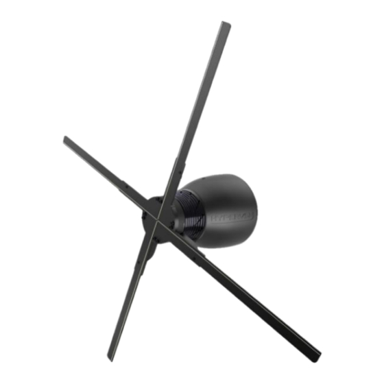
(https://hypervsn.com/media/AFU/Quick_start_guide.pdf and https://hypervsn.com/media/SoloApp/User_guide.pdf). The Device is designed for static mounting on walls or custom-made, stand-alone structures. The Device may be supplied with or without the remote control, depending upon configuration and region. © Copyright 2019 HYPERVSN. All rights reserved... - Page 5 Key components rotor (with four rays), stator, wall bracket, remote control (optional). ROTOR rays shaft STATOR indicators WALL BRACKET Picture 2. Device components Picture 3. Remote control (optional) © Copyright 2019 HYPERVSN. All rights reserved...
- Page 6 Picture 4. Device with the dome installed Note. The sockets at the bottom of the stator are intended to provide connection with HYPERVSN MasterBox. For more detailed information, see the Operating manuals for HYPERVSN MasterBox and HYPERVSN Wall. SOCKETS Picture 5.
-
Page 7: Technical Specifications
1.0A Input AC frequency 50/60Hz Net weight 2.8kg Noise figure on the Device axis 45Db (1 m from the Device) Fuse Ceramic 4A 250VAC 5X20mm Power cable length Power cable thickness 8mm (max) © Copyright 2019 HYPERVSN. All rights reserved... - Page 8 Operation of this equipment in a residential environment could cause radio interference. The Device is to be connected to single-phase alternating current mains (with 100-240V voltage and 50/60Hz frequency) and can be operated continuously while plugged in. © Copyright 2019 HYPERVSN. All rights reserved...
-
Page 9: Package Contents
– 5.3mm, for a concrete wall – 5.0mm. Fasteners – 3 pieces to attach the wall bracket (M5 mounting hardware, appropriate for the mounting surface – a partitioned or a concrete wall). © Copyright 2019 HYPERVSN. All rights reserved... -
Page 10: Device Installation Areas
5m high, it is recommended to install at least two Devices side by side; and in premises over 200 square meters and with ceilings 5m high it is recommended to install at least three Devices side by side. © Copyright 2019 HYPERVSN. All rights reserved... - Page 11 The recommended Device installation angle is 90° to the mounting surface. © Copyright 2019 HYPERVSN. All rights reserved...
-
Page 12: Device Assembly
If the Device is supplied disassembled, check that the shaft is perpendicular to the bottom (base) of the stator, the shaft should turn on its axis (rotate the shaft with your fingers). Contact your supplier if you notice any irregularities during your component check. © Copyright 2019 HYPERVSN. All rights reserved... - Page 13 Picture 8. Positioning the rotor (right) on the stator (left) Carefully take the rotor (avoiding any damage to the rays) and gently place it straight onto the shaft as shown below: Picture 9. Fitting the rotor onto the shaft © Copyright 2019 HYPERVSN. All rights reserved...
- Page 14 Tighten the binding screw until it stops by turning it to the right. Picture 10. Tightening in the binding screw If the assembly steps are performed correctly, there will not be any backlash of the stator or rotor elements. © Copyright 2019 HYPERVSN. All rights reserved...
-
Page 15: Device Installation
Mark the position of the 3 mounting holes on the wall. Drill 3 holes in the marked positions. Using the appropriate mounting hardware, firmly attach the wall bracket to a wall (Picture 12, steps 1-2). © Copyright 2019 HYPERVSN. All rights reserved... - Page 16 Attach the safety screw (supplied complete with the wall bracket) to the safety hole and screw it down (Picture 12, step 4). Attention. The proper Device installation angle is 90° to the mounting surface. When the Device is mounted, the shaft axis should be parallel to the ground. © Copyright 2019 HYPERVSN. All rights reserved...
-
Page 17: Device Operating Modes Overview
Setup (Hotspot) mode In the Setup (Hotspot) mode the Device creates a wireless network in close proximity to the Device. The network name is hypervsn-YYXXXXX, where YYXXXXX is a 7-digit serial number located on the base of the rotor. In this mode the Device displays the “BEGIN BY UPLOADING YOUR 3D MEDIA” message (Picture 14) if these is no content uploaded onto the Device or media playback is stopped. -
Page 18: Switching The Device On And Off
Important. While moving the Device do not hold onto rays. They can be easily broken if mishandled. Turning on the Device equipped with the remote control Put the mode switch on the stator into the counter-clockwise (left) position (Picture 16). Connect the Device to the power mains. © Copyright 2019 HYPERVSN. All rights reserved... -
Page 19: Status Indicators Of The Device
The Device is either not powered or the Device is in a normal working mode (displaying user content (if any) or messages uploaded by default). The red indicator is on The Device is connected to the power mains but is not turned © Copyright 2019 HYPERVSN. All rights reserved... - Page 20 The red and the green indicators 1. The rotor or the stator is out of order. are blinking 2. The rotor of Model M is attached to the stator of Model MS. Attention. The rotor only of Model MS must be used with the stator of Model MS (the rotor of Model MS has the “MS”...
-
Page 21: Device Initial Activation
Upon purchase, each customer receives a personal email invitation. If you have not received this, kindly contact your dealer or HYPERVSN customer service. Click Set my password in the email invitation you received or open your browser and paste the specified link into the address bar. - Page 22 Enter your password, confirm it, acknowledge that you have read the Privacy Notice (check I’ve read the Privacy Notice) and click Log in. The next page will open: Picture 20. CMS login page © Copyright 2019 HYPERVSN. All rights reserved...
- Page 23 The first seven fields contain information about your company. If it is incorrect, click Edit profile and edit the data, then go to the next step. This can also be done after completing the Device installation. © Copyright 2019 HYPERVSN. All rights reserved...
- Page 24 (move the mode switches). Turn the Device on again. The Device will start to display the “HYPERVSN” message. After a few seconds the “BEGIN BY UPLOADING YOUR 3D MEDIA” and “PLEASE ACTIVATE THE DEVICE” messages will start to alternate on the Device.
- Page 25 Picture 25. Messages that you should see before activation Navigate to the Wi-Fi settings on your laptop or any other device. The Wi-Fi network “hypervsn- YYXXXXX” will appear in 1-2 minutes in the list of available networks. Picture 26. Example of a list of available networks Connect to the “hypervsn-YYXXXXX”...
- Page 26 Picture 30. Form for the Device calibration If you have already mounted the Device on a wall, the calibration procedure may be performed at this step. Otherwise it should be performed later, after completing the initial activation procedure. © Copyright 2019 HYPERVSN. All rights reserved...
- Page 27 Picture 32. Step of the activation procedure Enter the required information for the Wi-Fi network that you plan to use with the Device. Click Save Network. Any number of networks may be used. © Copyright 2019 HYPERVSN. All rights reserved...
- Page 28 Device operation requires a direct Internet connection without any additional login screens. Login: example login example * * * * * login * * * * Distance to the router: up to 3m. >3 m Wi-Fi frequency: 2.4GHz. 2.4 GHz 5.0 GHz © Copyright 2019 HYPERVSN. All rights reserved...
- Page 29 Internet connection from your mobile phone by creating a Hotspot. Please note that your service provider may charge a fee for using the Hotspot. Click Activate (Picture 33) and look at the Device. The Device will start the booting animation. Picture 34. Booting animation on the Device © Copyright 2019 HYPERVSN. All rights reserved...
- Page 30 SSID you have entered at step 15. Picture 36. Activation error message If Wi-Fi network is not available, the following message will be displayed on the Device. Picture 37. “No internet” message © Copyright 2019 HYPERVSN. All rights reserved...
- Page 31 (Picture 15). If the Device is successfully connected to an Internet-enabled Wi-Fi network (set up at step 15), it is ready to be used and displays in your personal account at https://hypervsn.com/platform/devices. Click My Devices. © Copyright 2019 HYPERVSN. All rights reserved...
- Page 32 Picture 40. “My Devices” button You will see the Device that you have just activated, along with the list of your Devices activated previously (if any). “i” button LIST OF DEVICES Picture 41. “My Devices” tab © Copyright 2019 HYPERVSN. All rights reserved...
- Page 33 If the data is incorrect, choose Edit information in the open window (Picture 43), edit the data, click Save. After all these steps you will be able to create a media campaign and upload the content. © Copyright 2019 HYPERVSN. All rights reserved...
- Page 34 Go to the Dashboard and select the suitable guides to receive detailed instructions on how to manage the Device and the CMS. Picture 44. HYPERVSN tutorials © Copyright 2019 HYPERVSN. All rights reserved...
-
Page 35: Technical Maintenance
Device has been replaced. Clean any dust off of the Device. Important. When cleaning the Device, do not use a moist rag. Important. When cleaning the rays, use a very soft bristle brush. © Copyright 2019 HYPERVSN. All rights reserved... -
Page 36: Safety Provisions
Under NO circumstances touch the Device while the rays are rotating. The rays on the rotor become effectively invisible, which might pose a danger and cause injury. Since the HYPERVSN Display relates to TYPE A pluggable equipment it is necessary to have an easy- to-reach socket nearby. ... - Page 37 The user shall bare full responsibility for ensuring that the Device is utilized in a safe manner and complies with all specified safety measures as well as local laws and requirements. © Copyright 2019 HYPERVSN. All rights reserved...
-
Page 38: Disposal
Instead, please transfer it to an electric equipment recycling center for proper disposal. By adhering to disposal regulations, one can prevent causing potential damage to the environment resulting from mishandling this type of waste disposal. © Copyright 2019 HYPERVSN. All rights reserved... -
Page 39: Warranty And Maintenance
Attention. No changes shall be made to the Device without the manufacturer’s permission as it may void the user’s authority to operate the Device. © Copyright 2019 HYPERVSN. All rights reserved... - Page 40 2nd Floor Soho Wharf 1 Clink Street London SE1 9DG United Kingdom + 44 208 0685 328 info@hypervsn.com...
Need help?
Do you have a question about the MS and is the answer not in the manual?
Questions and answers