
Related Manuals for HYPERVSN Wall

Summary of Contents for HYPERVSN Wall
- Page 1 See Extraordinary Wall OPERATING MANUAL Integrated 3D Holographic Display System © Copyright 2018 HYPERVSN. All rights reserved...
-
Page 2: Table Of Contents
5.1 DEVICE ASSEMBLY (STEP 1) ............. 14 5.2 ROUTER SET UP (STEP 2) ............17 5.3 DEVICES ACTIVATION (STEP 3) ..........20 5.4 WALL INSTALLATION (STEP 4) ..........21 5.4.1 Calibration ................27 5.5 UPLOADING CONTENT TO DEVICES (STEP 5) ....31 5.5.1 Uploading media content to Devices via micro SD card... - Page 3 HYPERVSN Wall use. This Operating manual is designed as a general guide for HYPERVSN Wall (hereinafter referred to as the “Wall”). Please check the online manual at www.hypervsn.com for the most up-to-date Wall information. The Operating manual provides an overview of the Wall, HYPERVSN Device (hereinafter referred to as the “Device”, “Devices”), technical specifications, safety provisions, the...
-
Page 4: Wall Overview
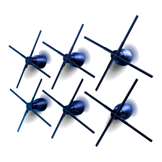
Before you start the setup of the Wall, please carefully read the Operating manual (supplied with the package) for information on the Device’s assembly and activation process. You will also find details on how to set up your account at HYPERVSN Content Management System (the CMS). - Page 5 For more detailed information about the Masterbox, see its exclusive Operating manual. Depending on the number of the Devices the Wall consists of, the Devices will be installed according to one of the specific patterns. Picture 2. Examples of the Wall pattern, (a) 6 vertical, (b) 6 horizontal All Wall Devices are mounted onto a surface (wall) by means of alignment mounts (long and short) according to the specific Wall pattern applied.
-
Page 6: Package's Content And Additional Required Components
Devices are going to be mounted onto – partitioned or concrete. Picture 4. Types of walls: (a) partitioned, (b) concrete The Wall may also be installed on customized surfaces constructed by customers, providing that the technical characteristics of the surfaces are consistent with the requirements for partitioned walls (seen in this manual). - Page 7 Screwdriver Philips (PH2) • For making mounting holes With a drill bit appropriate for the Drill mounting surface For mounting the Devices on a wall • Wrench/Grip socket wrench 13 mm (x2) Wrench Hexagon 5.0 mm (or similar) Masonry drill...
- Page 8 Router Cable (LAN) Line filter(s) Quantity depends on the number of Devices the Wall consists of. The required number of sockets for line filters equals to the number of Devices in a Wall. Sound facilities (if you are going to In accordance with customer’s needs...
-
Page 9: Technical Specifications
Rated frequency 60/50Hz Net weight 2.8kg (without an alignment mount) Fuse Ceramic 4A 250VAC 5X20mm Noise level from Device’s axis 45Db (measured 1m from the Device) Power cable length Power cable thickness 8mm (max) © Copyright 2018 HYPERVSN. All rights reserved... -
Page 10: Wi-Fi Network Requirements
Table 7. Network requirements WALL TYPE • With a built-in NTP-server or with Wall is not equipped with the Masterbox the capability to install an NTP - server. Note. NTP - (Network Time Protocol) – is a means of synchronizing clocks over the Internet. -
Page 11: Video Requirements
These set up instructions will be different to the ones given in this manual. In this case, you should install an NTP-server on your PC and use your PC while the Wall is in operation. Please contact support@hypervsn.com for further instructions. -
Page 12: Wall Installation Areas
The Wall may be installed at a height under 2,9m. In this case, the Wall must be surrounded by some sort of barrier that strictly forbids audiences from crossing There must be a minimum of 3m meters between the Wall and the safety barrier. -
Page 13: Mounting Surface Requirements
Do not install the Wall against white/lightly colored backgrounds or in close proximity to bright light sources such as, large LED displays or projector screens. It is not recommended to install the Wall under direct sunlight or light from lighting fixtures. -
Page 14: Wall Assembly Workflow
WALL ASSEMBLY WORKFLOW Follow the 5 steps below to assemble the Wall. DEVICE ASSEMBLY (STEP 1) Important. If the Devices have been stored in low temperatures, leave them indoors for • at least 2 hours before use. This avoids moisture condensing on internal components of the Devices, which otherwise may damage to the Devices. - Page 15 Picture 6. Positioning the rotor (right) on the stator (left) Carefully take the rotor (avoiding any damage to the rays) and gently place it straight onto the shaft as shown below. Picture 7. Fitting the rotor onto the shaft © Copyright 2018 HYPERVSN. All rights reserved...
- Page 16 Repeat the assembly procedure for each Device of the Wall. The Devices start working the second that they are plugged in. Before switching on the Devices, ensure that every person near the Wall keeps a safe distance of at least 0,5m.
-
Page 17: Router Set Up (Step 2)
Using the second port of the router and an Ethernet cable, link the router to your PC. Plug in the router. Picture 10. Connecting a router Turn on the PC. Click Start. Choose Settings. Picture 11. Settings command © Copyright 2018 HYPERVSN. All rights reserved... - Page 18 Choose Network & Internet. Picture 12. Network and Internet Click Ethernet → Change adapter options. Picture 13. Change adapter options command © Copyright 2018 HYPERVSN. All rights reserved...
- Page 19 Picture 14. Properties command Click Internet Protocol Version 4 (TCP/IPv4), click Properties. Picture 15. Properties button Check Obtain an IP address automatically, check Obtain DNS server address automatically, and then click OK. Picture 16. Properties window © Copyright 2018 HYPERVSN. All rights reserved...
-
Page 20: Devices Activation (Step 3)
Before you can use the Devices, you will first need to activate them and your licenses. For these activation procedures, see the Device Operating manual (supplied with each Device). Repeat the activation procedure for each Device of the Wall and activate your Device’s licenses. Attention. -
Page 21: Wall Installation (Step 4)
8mm. • If the Wall is installed on a partitioned wall and you would like to hide the Device’s power cords, ensure that the holes that you drill into wall are big enough to feed the AC plug used (region specific) through. - Page 22 Picture 19. Alignment mount BRACKET PLATE Picture 20. Disassembled alignment mount Take the bracket (Picture 20) and tighten it with the appropriate fasteners to a wall. Picture 21. Tightening the bracket to the wall © Copyright 2018 HYPERVSN. All rights reserved...
- Page 23 Picture 22. Removing the default mount Feed the Device power cord through the plate. Picture 23. Feeding the power cord through the plate Tighten the plate to the stator with the same four screws (Picture 22). © Copyright 2018 HYPERVSN. All rights reserved...
- Page 24 Screw the top and bottom screws (Picture 19) until fully tightened. Picture 24. Installed Device Alternatively, put the Devices power cords through the appropriate holes in a wall. Repeat steps 3-10 for each Device. Attention. Perform the Device’s wall mounting from the top to the bottom.
- Page 25 If you have made holes to hide the power cords, you may use them to hide Rj12 cables. When all Devices are attached to the wall make sure that the rays do not touch each other. Holding onto the rotor base, try to manually rotate the rays of each Device.
- Page 26 If you intend to use the Masterbox, connect the Masterbox to the Wall and mount it on a wall. For a more detailed description of this see the Operating manual for HYPERVSN Masterbox. Picture 28. Connection scheme Plugging the Wall in Connect a line filter(s) to the power mains.
-
Page 27: Calibration
5.4.1 Calibration Attention. Adjust the image angle on the Wall before launching any content on the Devices. Switch on the line filter(s) to launch all the Devices of the Wall. Run Sync App/SDK application exe-file. During the first Sync App/SDK launch a firewall pop-up window might appear. If this happens, select all the checkboxes in the window appeared, click Allow access. - Page 28 Picture 32. List of Devices, Device Settings tab Firmware version check Select the Device name with a checkbox (you may start with any Device). Go to the Device Settings tab (Picture 32). Click the Refresh button (Picture 33). © Copyright 2018 HYPERVSN. All rights reserved...
- Page 29 (Picture 33). Repeat this procedure for each Device of the Wall. If a firmware version is different for at least one of the Devices, contact support@hypervsn.com for more instructions (Additional steps will most likely be required to update the firmware.
- Page 30 Click Set rotation to apply changes. Picture 37. Set rotation button Repeat steps 8-11 for each Device to adjust the picture angle. Click Off in the Diagnostic screen section to exit the calibration mode. Picture 38. Off button © Copyright 2018 HYPERVSN. All rights reserved...
-
Page 31: Uploading Content To Devices (Step 5)
The content for the Wall is prepared according to the information the user provides. Users receive a link with their content prepared. There are two options for uploading video content to the Wall. The most suitable variant should be selected by the user: •... -
Page 32: Adding Content To Devices Via Sync App (Variant 2)
Example: rename Playlist_H-RYY0XXX1 to Playlist_H-RYY01000, because H- RYY01000 Device has №1 wall position. Repeat the current procedure with each playlist. Eject the micro SD card with content from your personal computer. Make sure all the Devices are in Operating Mode. - Page 33 Attention. In Player mode, Devices do not have the functionality to be managed via the CMS. In cases where this required, run Sync App/SDK application and choose the CRM indicator for the Device. © Copyright 2018 HYPERVSN. All rights reserved...
- Page 34 (Picture 44). The media file name matches the Device wall position and is labelled in the following format: XXXX._1, XXXXX._2, XXXXXX._3 etc. Picture 44. Selecting a media file Wait till the download is complete. © Copyright 2018 HYPERVSN. All rights reserved...
- Page 35 Picture 45. Checkboxes to select media files for a playlist The media will be displayed in the “Playlists” list. Picture 46. Playlist area, right arrow Enter a playlist name to the Playlist name field. Picture 47. Field to enter a playlist name © Copyright 2018 HYPERVSN. All rights reserved...
-
Page 36: Adding Custom Soundtracks (Optional)
The Devices do not have any audio output. For sound reproduction, use additional audio facilities. Adding a soundtrack to the Wall is similar to the process of adding content to Devices via Sync App/SDK application (variant 2). There are some additional requirements that must be met: •... - Page 37 Select a media file(s) with a checkbox(es) and adjust its order using Up and Down arrows (Picture 51) if necessary (media files must have the same order and the same duration as other videos). © Copyright 2018 HYPERVSN. All rights reserved...
- Page 38 Click the Right arrow button to send your playlist to the Device (Picture 51). Select your playlist with a checkbox and click Set Playlist. Picture 52. Selecting a playlist and uploading it to the Device © Copyright 2018 HYPERVSN. All rights reserved...
-
Page 39: Wall Operation
6. WALL OPERATION Attention. The Wall without the Masterbox connected operation requires permanent Wi-Fi connection. Do not turn the Wi-Fi off. To turn the Wall on: Switch it on/off, using the line filter(s). For Walls equipped with the Masterbox, additionally press the “On” button on the remote control. -
Page 40: Safety Provisions
• positioned strictly out of direct public reach. The user confirms that, if positioning the Wall out of direct public reach is not possible, he/she must immediately inform the manufacturer and not proceed with the installation under such circumstances. •... -
Page 41: Troubleshooting
Devices to the router network. • The distance between the router and the Wall is more than 3m. Reduce the distance between the router and the Wall. Try to use an alternative router channel (if the previous step did not help). -
Page 42: Warranty
Attention. No changes shall be made to the Device without the manufacturer’s permission as it may void the user’s authority to operate the Device. © Copyright 2018 HYPERVSN. All rights reserved... -
Page 43: Disposal
Instead, please pass it to an electric equipment recycling center for proper disposal. By adhering to disposal regulations, one can prevent causing potential damage to the environment resulting from mishandling this type of waste disposal. © Copyright 2018 HYPERVSN. All rights reserved... -
Page 44: Application 1
FOR AC PLUGS SCREWS Picture A1.1. Marking template Depending on the type of AC plug used in your country, select the appropriate size of holes to feed AC plugs through (US, EU, UK). © Copyright 2018 HYPERVSN. All rights reserved... - Page 45 INSTALLATION PATTERNS Picture A1.2. Example of the Wall patterns: grey – front, white – back 6 Devices - horizontal Meters Inches Height 0.97 Width 1.38 6 Devices - vertical Meters Inches Height 1.38 Width 0.97 © Copyright 2018 HYPERVSN. All rights reserved...
- Page 46 9 Devices Meters Inches Height 1.38 Width 1.38 12 Devices - horizontal Meters Inches Height 1.38 Width 1.78 © Copyright 2018 HYPERVSN. All rights reserved...
- Page 47 12 Devices - vertical Meters Inches Height 1.78 Width 1.38 © Copyright 2018 HYPERVSN. All rights reserved...
- Page 48 15 Devices - horizontal Meters Inches Height 1.38 Width 2.19 15 Devices - vertical Meters Inches Height 2.19 Width 1.38 © Copyright 2018 HYPERVSN. All rights reserved...
- Page 49 24 Devices - horizontal Meters Inches Height 1.78 Width 3.39 © Copyright 2018 HYPERVSN. All rights reserved...
- Page 50 24 Devices - vertical Meters Inches Height 3.39 Width 1.78 © Copyright 2018 HYPERVSN. All rights reserved...
- Page 51 28 Devices- horizontal Meters Inches Height 1.78 Width 3.39 © Copyright 2018 HYPERVSN. All rights reserved...
- Page 52 28 Devices - vertical Meters Inches Height 3.39 Width 1.78 © Copyright 2018 HYPERVSN. All rights reserved...
- Page 53 2nd Floor Soho Wharf 1 Clink Street London SE1 9DG United Kingdom + 44 208 0685 328 info@hypervsn.com © Copyright 2018 HYPERVSN. All rights reserved...
Need help?
Do you have a question about the Wall and is the answer not in the manual?
Questions and answers