Advertisement
Quick Links
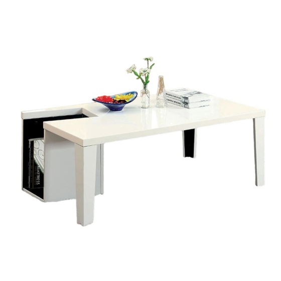
CM4644WH-C
ASSEMBLY RATING
The Assembly Rating is a 5-point system that
shows the degree of effort needed in
assembling a specific product (with 1 being
easy and 5 being difficult). For some
products, two persons are recommended.
EASY
Assembly Instructions
CM4644RD-C
DIFFICULT
Page 1 of 6
Tools Required for Assembly:
Allen Wrench
Phillips Screwdriver
Flat-Head Screwdriver
CM4644BK-C
(Included)
(Not Included)
(Not Included)
Rev.14-03-27
Advertisement

Related Manuals for Furniture of America CM4644WH-C


Summary of Contents for Furniture of America CM4644WH-C
- Page 1 Assembly Instructions CM4644WH-C CM4644BK-C CM4644RD-C ASSEMBLY RATING Tools Required for Assembly: The Assembly Rating is a 5-point system that shows the degree of effort needed in Allen Wrench assembling a specific product (with 1 being (Included) easy and 5 being difficult). For some products, two persons are recommended.
- Page 2 Page 2 of 6...
- Page 3 Before you begin, please read Page 2 of “Assembly and Care Advice”. And remember, do not tighten until each step is completed or instructed. Parts List Hardware List #1 x 1 pc #A x 3 pcs Table Top Flat Washer #B x 3 pcs #2 x 3 pcs Lock Washer...
- Page 4 CAM LOCK FASTENER ASSEMBLY INSTRUCTIONS Note: Every cam lock bolt must have a cam lock connector in order to fasten the parts together. Align the cam connector with its Insert the cam lock side opening (or arrow) bolt into the pre- Secure the pointing to the small drilled hole above...
- Page 5 Insert one cam bolt (#F1) into the rear panel (#3) and one cam connector (#F2) into the bottom panel (#6). See diagram below and refer to “CAM LOCK FASTENER ASSEMBLY INSTRUCTIONS” for connecting those parts together. #F1 x 1 pc #F2 x 1 pc Insert 4 cam bolts (#F1) and 2 cam connectors (#F2) into the right panel (#5).
- Page 6 Insert 4 cam bolts (#F1) and 2 cam connectors (#F2) into the left panel (#4). See diagram below and refer to “CAM LOCK FASTENER ASSEMBLY INSTRUCTIONS” for connecting those parts together. Once locked, insert a 7 cam covers (#G) over the 7 cam connectors (#F2) as shown below. #F1 x 4 pcs #F2 x 2 pcs #G x 7 pcs...
Need help?
Do you have a question about the CM4644WH-C and is the answer not in the manual?
Questions and answers