
Related Manuals for Schaltbau CF Series


Summary of Contents for Schaltbau CF Series
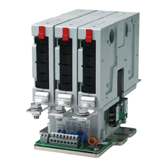
- Page 1 Contactors CF series Multipole AC power contactors for 300 A or 600 A with NO or NC switching chambers Installation and maintenance instructions Manual C60-M.en...
-
Page 2: Table Of Contents
5.2.3 Examples of CO contactors (AC/DC) – 200 and 300 A ..............17 5.2.4 Examples of CO contactors (AC/DC) – 400 A ...................18 Storage..............................19 Unpacking .............................19 Unpacking the device ..........................19 Check parts for transport damage ......................19 Contactors CF Series – Installation and Maintenance Instructions 2021-11-03 / V1.0... - Page 3 9.3.1 Replacing the arcing chamber inserts ....................38 9.3.2 Replacing the switching elements ......................38 9.3.3 Replacing the auxiliary switches ......................40 10. Spare parts ............................41 11. Technical data ............................42 12. Disposal ..............................42 Contactors CF Series – Installation and Maintenance Instructions 2021-11-03 / V1.0...
-
Page 4: Important Basic Information
This manual refers to multi-pole AC/DC power contac- Conventions for this manual tors of the CF series with nominal voltages of 1,500 V This manual describes the installation and maintenance and 3,000 V. The contactors can be equipped with both of the contactors. -
Page 5: Duties Of The Operating Company
Contactors may not be used without other safety precautions in potentially explosive atmospheres and/or in aggressive media. Contactors CF Series – Installation and Maintenance Instructions 2021-11-03 / V1.0... -
Page 6: Hazards And Safety Precautions
DANGER All checks and the replacement of components or groups of components may only be carried out by qualified personnel according to the instructions of Schaltbau. All spare parts must be parts deli- vered by or released by Schaltbau. Contactors CF Series – Installation and Maintenance Instructions... -
Page 7: Other Hazards
Depending on the product type, contactors can contain permanent magnets. These permanent magnets can destroy the data on the magnetic strips of credit or similar cards. Keep credit or similar cards away from the contactors. Contactors CF Series – Installation and Maintenance Instructions 2021-11-03 / V1.0... -
Page 8: Product Information
Compact dimensions – high performance range: 1,500 or 3,000 Volt AC/DC, 3x 600 amps, frequen- The highly modular CF series comes with compact cies up to 400 Hertz 1-pole up to 6-pole AC/DC power contactors for loads up to 600 A and 3,000 V for inverter-fed alternating cur- Innovative application-dependent arcing cham- rent drives with higher frequencies. -
Page 9: Description
Coil drive wide (2 drives) Coil drive small (1 drive) Switching elements with NO configuration: - max. 6 switching elements with coil drive wide - max. 3 switching elements with coil drive small Contactors CF Series – Installation and Maintenance Instructions 2021-11-03 / V1.0... -
Page 10: Cf - 3,000 V, 200 And 300 A, Ac/Dc Contactors (No Configuration Examples)
- max. 6 switching elements with coil drive wide - max. 3 switching elements with coil drive small Insulating plates (required for 3,000 V contactors) Insulating end panels (required for 3,000 V contactors) Contactors CF Series – Installation and Maintenance Instructions 2021-11-03 / V1.0... -
Page 11: Cf - 1,500 V/3,000V, 200 And 300 A, Ac/Dc Contactors (Nc Configuration Examples)
Coil drive wide (2 drives) Coil drive small (1 drive) Switching elements with NC configuration: - max. 4 switching elements with coil drive wide - max. 2 switching elements with coil drive small Contactors CF Series – Installation and Maintenance Instructions 2021-11-03 / V1.0... -
Page 12: Cf - 1,500 V/3,000 V, 400 A, Ac/Dc Contactors (No Configuration Examples)
Coil drive wide (2 drives) Coil drive small (1 drive) Switching elements (400 A) - max. 4 switching elements with coil drive wide - max. 2 switching elements with coil drive small Contactors CF Series – Installation and Maintenance Instructions 2021-11-03 / V1.0... -
Page 13: Cf - 1,500 V, 200 And 300 A, Ac/Dc Contactors (Co Configuration Examples)
1,500 V, 200 and 300 A, AC/DC contactors – coil drive designs and switching elements (CO configuration examples) Coil drive wide (2 drives) Coil drive small (1 drive) C1 Switching elements with NO configuration C2 Switching elements with NC configuration Contactors CF Series – Installation and Maintenance Instructions 2021-11-03 / V1.0... -
Page 14: Cf - 3,000 V, 200 And 300 A, Ac/Dc Contactors (Co Configuration Examples)
Coil drive small (1 drive) C1 Switching elements with NO configuration C2 Switching elements with NC configuration Insulating plates (required for 3,000 V contactors) Insulating end panels (required for 3,000 V contactors) Contactors CF Series – Installation and Maintenance Instructions 2021-11-03 / V1.0... -
Page 15: Switching Element Configuration - 200 And 300 A
Latch / unlatch button Magnetic cores – only for DC versions Ceramic arcing chamber insert (2x) Arcing chamber insert with metal arcing plates (2x) Plastic arcing chamber insert (2x) Contactors CF Series – Installation and Maintenance Instructions 2021-11-03 / V1.0... -
Page 16: Configuration Examples Of The Cf Contactor Series (Stock Items)
Fig. 9: Configuration examples of 200 and 300 A, NO/NC contactors (the figures show DC versions, AC versions are similar but without pole plates and magnetic cores) Contactors CF Series – Installation and Maintenance Instructions 2021-11-03 / V1.0... -
Page 17: Examples Of No And Nc Contactors (Ac/Dc) - 400 A
Fig. 11: Configuration examples of 200 and 300 A CO contactors (the figures show DC versions, AC versions are similar but without pole plates and magnetic cores) Contactors CF Series – Installation and Maintenance Instructions 2021-11-03 / V1.0... -
Page 18: Examples Of Co Contactors (Ac/Dc) - 400 A
Fig. 12: Configuration examples of 400 A CO contactors (the figures show DC versions, AC versions are similar but without pole plates and magnetic cores) Contactors CF Series – Installation and Maintenance Instructions 2021-11-03 / V1.0... -
Page 19: Storage
Check parts for transport damage ATTENTION If parts are damaged, functional reliability of the con- tactor has been lost. Before installing, check all parts for possible transport damage. Do not install damaged parts. Contactors CF Series – Installation and Maintenance Instructions 2021-11-03 / V1.0... -
Page 20: Installation
(min. 8.8) of the screws/nuts used. ±0.1 [mm] Fig. 14: Dimensions and layout of mounting holes for coil drive small (dimensions not to scale) Contactors CF Series – Installation and Maintenance Instructions 2021-11-03 / V1.0... -
Page 21: Mounting Positions
(A and B) and non-permitted mounting po- When installing, ensure that no dirt can get into the sitions (C). contactor as a result of surrounding building activi- ties. Contactors CF Series – Installation and Maintenance Instructions 2021-11-03 / V1.0... -
Page 22: Tools Required
Tighten the mounting screws to the specified torque, which depends on the strength class (min. 8.8) of the screws/nuts used. Contactors CF Series – Installation and Maintenance Instructions 2021-11-03 / V1.0... -
Page 23: Electrical Connection
If busbars are used for the main power circuit, they must not be wider than the fixed contacts. To secure the main terminal screws so that they Contactors CF Series – Installation and Maintenance Instructions 2021-11-03 / V1.0... -
Page 24: Safety
8.2.4 Tools required - Socket spanner set - Open-ended spanner set - Torque spanner - Continuity tester - Cable ties Contactors CF Series – Installation and Maintenance Instructions 2021-11-03 / V1.0... -
Page 25: Connecting The Auxiliary Switches
Check the routing of the wiring. Wires must not be squeezed or bent. If applicable bundle and secure the wires using cable ties. Fig. 19: Connecting the auxiliary switches (wide coil drives) Contactors CF Series – Installation and Maintenance Instructions 2021-11-03 / V1.0... -
Page 26: Connecting The Coil
Fig. 22: Connecting the coil (small coil drives) Check the routing of the wiring. Wires must not be squeezed or bent. If applicable bundle and secure the wires using cable ties. Contactors CF Series – Installation and Maintenance Instructions 2021-11-03 / V1.0... -
Page 27: Connecting The Earth Terminal
(2). - Schaltbau recommends using Schnorr washers (or similar). Tighten the terminal screws (3) to a torque of 8 - 10 Nm. Fig. 24: Connecting the earth terminal (small coil drives) Contactors CF Series – Installation and Maintenance Instructions 2021-11-03 / V1.0... - Page 28 Fig. 26: Connecting the main contacts with cables: Connection example for NO contactors with small coil drives Fig. 28: Connecting the main contacts with cables: Connection example for NC contactors with wide coil drives Contactors CF Series – Installation and Maintenance Instructions 2021-11-03 / V1.0...
- Page 29 8 - 10 Nm 8 - 10 Nm 8 - 10 Nm Fig. 30: Connecting the main contacts with cables: Connection example for CO contactors with wide coil drives Contactors CF Series – Installation and Maintenance Instructions 2021-11-03 / V1.0...
- Page 30 Connection example for NC contactors with small coil 8 - 10 Nm drives Fig. 32: Connecting the main contacts with busbars: Connection example for NO contactors with small coil drives Contactors CF Series – Installation and Maintenance Instructions 2021-11-03 / V1.0...
- Page 31 8 - 10 Nm 8 - 10 Nm 8 - 10 Nm Fig. 36: Connecting the main contacts with busbars: Connection example for CO contactors with wide coil drives Contactors CF Series – Installation and Maintenance Instructions 2021-11-03 / V1.0...
-
Page 32: Checks
After every installation or after maintenance, check the contactor for correct operation in accor- dance with the following standards: - EN/IEC 60077-2 - EN/IEC 60947-4-1 Contactors CF Series – Installation and Maintenance Instructions 2021-11-03 / V1.0... -
Page 33: Maintenance
The presence of a voltage-free state can only be clearly identified by a qualified electrician. When the work has been concluded, follow the procedure in reverse. Preventive maintenance Contactors of the CF series are maintenance-free within If the contactors are operated in a particularly dirty the rated mechanical life time. The electrical life time... -
Page 34: Regular Tests/Checks
Base plate/mounting Check for: In case of faults: flange loose or missing fastening elements tighten loose fastening elements im- mediately replace missing fastening elements tighten a loose contactor immedi- ately Contactors CF Series – Installation and Maintenance Instructions 2021-11-03 / V1.0... - Page 35 In case of faults: dirt if damaged or heavily worn, replace the complete coil drive unit damage or heavy wear damage due to operation with impermissible, too high coil voltage Contactors CF Series – Installation and Maintenance Instructions 2021-11-03 / V1.0...
-
Page 36: Removing The Arcing Chamber Inserts
Make sure that all arcing chamber inserts are latched securely. Fig. 37: Removing the arcing chamber inserts (example for contactors with wide coil drives) Contactors CF Series – Installation and Maintenance Instructions 2021-11-03 / V1.0... -
Page 37: Checking The Arcing Chamber Inserts
Plastic arcing chamber insert Arcing chamber insert with metal arcing plates Ceramic arcing chamber insert Fig. 41: Checking the main contacts for wear (example for contactors with small coil drives) Contactors CF Series – Installation and Maintenance Instructions 2021-11-03 / V1.0... -
Page 38: Corrective Maintenance
- Torque spanner Precondition The main contacts are disconnected, see “8.2.8 Con- Fig. 43: Replacing the switching elements (example for con- necting the main contacts”. tactors with small coil drives) Contactors CF Series – Installation and Maintenance Instructions 2021-11-03 / V1.0... - Page 39 Tighten all fixing screws (2) to a torque of 5 Nm. Reconnect the main contacts, see “8.2.8 Connect- ing the main contacts”. Finally, subject the contactor to a complete check as described in section “8.3 Checks” on page 32. Contactors CF Series – Installation and Maintenance Instructions 2021-11-03 / V1.0...
-
Page 40: Replacing The Auxiliary Switches
Plug the receptacles of the control wires back on to the contacts of the auxiliary switches (2). Check the correct connection of the control wires- to the auxiliary switches. Contactors CF Series – Installation and Maintenance Instructions 2021-11-03 / V1.0... -
Page 41: Spare Parts
CF Switching element complete, 400 A NC configuration Auxiliary switch S870 gold contacts Auxiliary switch S870 silver contacts CF Insulating plate CF Coil drive wide, complete CF Coil drive small, complete Contactors CF Series – Installation and Maintenance Instructions 2021-11-03 / V1.0... -
Page 42: Technical Data
Technical data 11. Technical data Technical data and information on the material proper- ties for the contactors of the CF series are given in our C60 catalogue. Schaltbau products are subject to continual improve- ment. Therefore, the product information in catalogues, data sheets, etc. - Page 43 Notes Notes Contactors CF Series – Installation and Maintenance Instructions 2021-11-03 / V1.0...
- Page 44 High-voltage heaters ■ High-voltage roof equipment ■ Equipment for electric brakes ■ Design and engineering of train electrics to customer requirements We reserve the right to make technical alterations without prior notice. Printed in Germany For updated product information visit www.schaltbau.com...
Need help?
Do you have a question about the CF Series and is the answer not in the manual?
Questions and answers