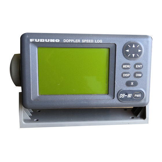
Furuno DS-80 Installation Manual
Doppler speed log
Hide thumbs
Also See for DS-80:
- Operator's manual (40 pages) ,
- Installation manual (83 pages) ,
- Operator's manual (41 pages)
Table of Contents
Advertisement
SAFETY INSTRUCTIONS ................................... i
SYSTEM CONFIGURATION .............................. ii
EQUIPMENT LISTS .......................................... iii
1. MOUNTING .................................................... 1
1.1 Category of Equipment ................................. 1
1.2 Display Unit .................................................. 2
1.3 Transceiver Unit ............................................ 3
1.4 Transducer Unit ............................................ 4
1.5 Distribution Box .......................................... 21
1.6 Terminal Box (option) .................................. 21
Indicator (option) ....................................... 22
1.8 Junction Box (option) .................................. 22
1.9 Dimmer (option) .......................................... 22
2. WIRING ........................................................ 23
2.1 Precautions for Cable Installation ............... 23
2.2 Wiring of Distribution Box ........................... 23
2.3 Wiring of Transceiver Unit ........................... 26
2.4 Wiring of Terminal Box ................................ 27
Distance Indicator) ..................................... 28
2.6 Grounding ................................................... 28
2.7 Wiring Check .............................................. 28
3. SYSTEM SETTINGS .................................... 29
3.1 Transducer Adjustment ............................... 29
3.2 Setting of System Menu 2 ........................... 30
3.3 Checking the Interconnection ..................... 31
3.4 Setting of Maximum Speed Range ............. 32
3.5 Ship's Speed Adjustments .......................... 32
3.6 Setting for Analog Display ........................... 33
3.7 DIP Switch Settings .................................... 34
All brand and product names are trademarks, registered trademarks or service marks of their respective holders.
Installation Manual
DOPPLER SPEED LOG
4. CHANGING AC POWER TAP .................. 36
CALIBRATION ............................................. AP-1
PACKING LISTS ............................................ A-1
OUTLINE DRAWINGS ................................... D-1
INTERCONNECTION DIAGRAMS ................ S-1
www.furuno.com
DS-80
Model
Advertisement
Table of Contents

Related Manuals for Furuno DS-80


Summary of Contents for Furuno DS-80
-
Page 1: Table Of Contents
Installation Manual DOPPLER SPEED LOG DS-80 Model SAFETY INSTRUCTIONS ........i 4. CHANGING AC POWER TAP ....36 SYSTEM CONFIGURATION ......ii EQUIPMENT LISTS .......... iii CALIBRATION ..........AP-1 1. MOUNTING ............ 1 PACKING LISTS ..........A-1 1.1 Category of Equipment ......... 1 OUTLINE DRAWINGS ........ - Page 2 ・FURUNO Authorized Distributor/Dealer 9-52 Ashihara-cho, Nishinomiya, 662-8580, JAPAN A : FEB 2000 Printed in Japan All rights reserved. X2 : DEC . 14, 2020 Pub. No. IME-72470-X2 (TAYA ) DS-80 0 0 0 8 0 8 8 9 8 1 9...
-
Page 3: Safety Instructions
The tank shall be strong enough to Transceiver Unit 2.00 m 1.15 m withstand the water pressure in fully loaded conditions in rough weathers. FURUNO Terminal Box 0.85 m 0.50 m Electric Co., Ltd. is not liable to any loss of ship and personnel which is caused by in- stallation procedures. -
Page 4: System Configuration
SYSTEM CONFIGURATION... -
Page 5: Equipment Lists
EQUIPMENT LISTS Standard supply Name Type Code No. Remarks Display Unit DS-800 Distribution Box DS-801-100 100 VAC DS-801-110 110 VAC DS-801-115 115 VAC DS-801-200 200 VAC DS-801-220 220 VAC DS-801-230 230 VAC Transceiver Unit DS-810 Transducer Unit DS-820 select 10/20/30/40m cable Terminal Box DS-802 Spare Parts... - Page 6 Optional equipment Name Type Code No. Remarks Terminal Box DS-802 000-029-048 1 set w/CP65-00903 Dimmer DS-F25 1 set 100-120 VAC, flush mount DS-FE25 1 set 200-240 VAC, flush mount DS-S25 1 set 100-120 VAC, bulkhead DS-SE25 1 set 200-240 VAC, bulkhead Junction Box CI-630 000-069-770...
-
Page 7: Mounting
1. MOUNTING NOTICE Do not apply paint, anti-corrosive sealant or contact spray to coating or plastic parts of the equipment. Those items contain organic solvents that can damage coating and plastic parts, especially plastic connectors. Category of Equipment Equipment for protected area •... -
Page 8: Display Unit
Display Unit 1.2.1 Mounting considerations The display unit can be installed on a tabletop, on the overhead, on the bulkhead or flush mounted in a console or panel. When selecting a mounting location for the display unit keep the following in mind. •... -
Page 9: Transceiver Unit
F type Make a cutout of 167 X 92 mm. Attach the cosmetic panel (supplied) to the display unit with hex bolts (M6X12, supplied) and spring washers (M6, supplied). Fix the display unit to the mounting location with four tapping screws (5X20, supplied). S type Make a cutout 167 X 92 mm. -
Page 10: Transducer Unit
Mounting Location To decide the location of the transducer, the following points should be taken into account. • Locate the transducer of DS-80 at least 2.5 m from the transducer of an echo sounder. DOPPLER SPEED LOG TRANSDUCER STERN 2500 mm or more... - Page 11 1.4.2 Mounting of transducer Confirm that a metal cover is attached to the transducer. For seachest except DS-850, remove the hose clamp from the top of transducer. Mounting of Flush Type Seachest DS-850 Fit the transducer (1) and spacer (7) to the bottom plate (3). With the “FORE”...
- Page 12 Mounting of Flush Type Seachest DS-784 (ref. Dwg. C7222-T06) The seachest DS-784 is delivered temporarily assembled with the transducer. Loosen lock nut (5) with a wrench (hex. size: 50 mm) and take off cap nut (4) from top cover (3) together with gasket (6) and flat washer (7).
- Page 13 Flush mount, Projection Type Seachest DS-783 (ref. Dwg. E7222-T-03) Loosen lock nut (5) with a wrench (hex. size: 50 mm) and take off cap nut (4) from hull flange (3) together with gasket (6) and flat washer (7). (It is not necessary to draw the cap nut completely out from the cable.) Unscrew hex.
- Page 14 Mounting of Projection Type Seachest DS-781 (ref. Dwg. C72222-T05) Weld doubling plate (supplied by shipyard) to hull plate. Remove the M10 bolts, and take out transducer fixing flange (2) (including transducer) from transducer housing (1). Determine the projection distance, and cut transducer housing (1). The horizontal error should be within 1°.
- Page 15 Gate valve, Projection Type Transducer DS-782 (ref. Dwg. C7222-T02) (12)(13)(14) (10) (11) (19) (16)(17)(20) (21)(22)(23) (18) Face B (15)(16)(17) (18) Face A DS-782 Separate hull flange (3) and flange (4) (with transducer (1) and shaft (5)) from gate valve (2) by removing hex.
- Page 16 10. Lower shaft (5) completely and fasten hex. socket bolt (23) and (26) 11. Lower the transducer by turning the handle until the transducer case (6) touches the hull flange (3). 12. Confirm that the hull plate projects by 24 mm. Note: Never weld the hull flange or transducer tank when the transducer is being fitted, nor weld near the transducer of other equipment.
- Page 17 1. Unfasten M16 nut (3) and spring washer (11) from the assembled gate valve to remove the five items shown below. • Gate valve (20) Shaft assy. • Spacer (3) • Gasket 1(18) Gasket2 (18) • Gasket 2(18) Gate valve (20) •...
- Page 18 Jubilee clip Do not remove this screw. Remove these four screws. Removing Jubilee clip Removing flat-head Phillips screws 12. Pass the transducer cable through the shaft from the flange side. 13. Apply Three Bond (1104 200G:local supply) to the top side of the transducer evenly. 14.
- Page 19 16. Fasten the gland (19) to the top of the shaft (5). Gland (19) Flat washer (8) Gasket (7) Flat washer (8) The fore mark on the shaft Flange (4) Check that they are aligned. Hex. nut (15)(M4x16) Seal washer (16)(M4) Apply Three Bond here.
- Page 20 23. Loosely fasten two sets of M8 hex. bolt (13) and M8 spring washer (14) at the top side of the lock ring (6). 24. Tightly fasten the M8 hex. bolt (13) tightly and the M8 spring washer (14) at the lateral side of the lock ring.
- Page 21 How to open, close the gate valve Loosen the two nuts fixing the gland gasket until the handle can be turned. Operate the handle to open or close the gate valve. When closing the gate valve If additional tightening is necessary after turning the handle by hand, prepare separate handle extensions.
- Page 22 Note 1: The liquid gasket for installation may not be supplied due to export regulations. If the liquid gasket TB1121 is not included in the installation materials, prepare the liquid gasket specified in your country. Note 2: The ball valve requires service space of 700 mm. For details, see the installation drawing at the back of this manual.
- Page 23 Fasten M16 nut (10) and M16 flat washer (11) loosely to the stud bolt of the flange (3) loosely. Unfasten two sets of hex. bolt (13) and M8 spring washer (14) from the top side of the shaft to remove the fixing plate (21). Remove the gland (19), gasket (7) and washer (8) (2 pcs.) from the shaft.
- Page 24 13. Apply the Liquid Gasket TB1121 to the thread part of hex. bolt (15) with seal washer (16) and use them to fasten the transducer. Check that the fore mark on the shaft is aligned with the projection at the bottom of the transducer. 14.
- Page 25 20. Insert the shaft so the projection on the transducer (1) fits in the groove on the flange (3). Move the shaft up and down by hand to confirm that it moves smoothly. 21. Tighten the M16 nut (8 pcs.) on the ball valve (20). 22.
- Page 26 26. Check that all bolts are fastened tightly. 27. Paint the ball valve (20) and the flange (3) the same color as ship’s body. Paint only gray-colored areas; for other parts, seal with masking tape. Remove the tape when the paint dries.
-
Page 27: Distribution Box
Distribution Box The distribution box can be mounted on the deck or on a bulkhead. Consider the following points when selecting a mounting location. • Select a location which is both well ventilated and low in humidity to keep the unit cool. •... -
Page 28: Digital Indicator, Distance Indicator (Option)
1.7 Digital Indicator, Distance Indicator (option) The digital indicator and distance indicator use the same housing as the display unit. Refer to the section 1.2 Display Unit for mounting instructions. Junction Box (option) 1.8.1 Mounting considerations The junction box forms a joint between the distribution box and the transceiver unit, and it is designed to be mounted on a bulkhead. -
Page 29: Wiring
Cable carrying switching waves generated by thyristor, etc. • Transmission antenna cable of radio equipment. Other cables of DS-80 Observe the following guidelines to prevent noise, interference problem. • When the cables run in parallel with power cables, separate them 400 mm at minimum. - Page 30 Fabrication of DPYCY-1.25/TTYCYS-1 (power cable, contact signal, analog signal, dimmer) DPYCY-1.25 is a Japan Industrial Standard (JIS) cable. Use the equivalent. DPYCY-1.25 cable doesn’t have shield. Armor within 350 Insulation Anticorrosive Shield Sheath Vinyl S =1.25 mm Sheath =1.35 mm FV2-M4 Wind the shield.
- Page 31 Fabrication of TTYCY-3S (transducer unit) TTYCY-3S is a Japan Industrial Standard (JIS) cable. Use the equivalent. 350 mm approximately Shield Armor Vinyl sheath Conductor Crimp-on Lug S =1.25 mm FV2-M4 Anticorrosive sheath =1.35 mm Remove the shield between (Sectional view) the fixing plate and terminal board.
-
Page 32: Wiring Of Transceiver Unit
Wiring of Transceiver Unit Fabrication of cable TTYCY-3S, 65S1213/65S1239 Cut the cables to fix them at the plate in the unit with a cable tie, leaving some slack for servicing and checking ease. Shield wire should be fixed at the plate. Twist pair cables together before connecting to the board. -
Page 33: Wiring Of Terminal Box
Wiring of Terminal Box Fix the cables with the cable tie at the fixing plate. All cables except the power cable should be fixed by the clamp with the armor. Fabrication of TTYCY-2S (for display unit and digital indicator/distance indicator) Within 120 mm Anticorrosive sheath... -
Page 34: Display Unit (Digital Indicator, Distance Indicator)
2.5 Display Unit (Digital Indicator, Distance Indicator) Use the cable assemblies MJ-A7SPF0009-020 and MJ-A6SPF0013-020 (supplied). Connect the cable at the rear of the display unit, and fabricate the other end of the cable for connection to the terminal box. Refer to the interconnection diagram at the end of this manual. Grounding This equipment uses pulse signals which may cause interference to other electronic equipments It is strongly recommended to ground all cables referring to the guidelines below. -
Page 35: System Settings
3. SYSTEM SETTINGS Transducer Adjustment Transducer mounted error, which causes incorrect speed value, can be compensated through the menu (Range: -45°to +45°). Press the [MENU] key to display the main menu. MENU DISTANCE RUN DISPLAY DEMO SYSTEM MENU SYSTEM MENU 2 Main menu Select SYSTEM MENU and press the [ENT] key to display the system menu. -
Page 36: Setting Of System Menu 2
Setting of System Menu 2 System menu 2 provides for selection of display language and dimmer control, as well as a diagnostic facility. Dimmer setting Select the adjustment method of panel dimmer, internal or external. Press the [MENU] key to display the main menu. Select SYSTEM MENU 2 and then press the [ENT] key. -
Page 37: Checking The Interconnection
Setting of language The display language can be selected for English or Japanese. Press the [MENU] key to display the main menu. Select SYSTEM MENU 2 and press the [ENT] key to display the system menu 2. Select LANG. And press the [ENT] key to display the language pop-up menu. E N G L I S H Language pop-up window Select ENGLISH or JAPANESE with ... -
Page 38: Setting Of Maximum Speed Range
Select DATA OUTPUT and press the [ENT] key. Press to select ON and press the [ENT] key. Press the [DISP] key. 10. Confirm the value displayed is the same as it entered at step 5. Confirm the same as speed is shown on external equipment (radar, GPS, etc.). 11. -
Page 39: Setting For Analog Display
Setting for Analog Display When the analog indicator is connected, synchronize the speed displays of DS-80 display unit and analog display as follows. Analog interface Current output: 4 to 20 mA (-10 to 30 kn) Voltage output: -3.3 to 10VDC (-10 to 30 kn) Connected to TB2 ANA1 (analog 1) 1. -
Page 40: Dip Switch Settings
Set to OFF. R100 R145 Power switch: Upper Distribution box DS-801 DIP Switch Settings JPW Board (65P6010) S4-#6 The default setting (OFF) outputs only sentences VBW and VLW of all NMEA sentences input. DIP switch S4-#6 setting Output NMEA sentences VBW, VLW All NMEA sentences S4-#8... - Page 41 KCP Board (65P6020) S1-#6 Turn on/off flashing of the indication “STW” when the thermistor value is abnormal. S1-#6 Flashing (default setting) No flashing S1-#5, #8 Changeover of IEC61162-1 Edition. S1-#5 ON S1-#5 OFF S1-#8 ON IEC61162-1 Ed3 / Ed4 IEC61162-1 Ed3 / Ed4 S1-#8 OFF IEC61162-1 Ed2 IEC61162-1 Ed1 (default setting)
-
Page 42: Changing Ac Power Tap
4. CHANGING AC POWER TAP The DS-80 is shipped from the factory ready for connection to the ordered AC power supply. To connect to a different AC power supply, change the jumper wiring on the terminal board as shown on the next page. - Page 43 100VAC 110VAC 120VAC 200VAC 220VAC 230VAC Jumper wire AC power supply and jumper wires on the terminal board in the distribution box...
-
Page 44: Calibration
B in the illustration. Speed is obtained from the following equations. Note that Sg1 and Sg2 are both speeds over the ground (SOG); however the DS-80 provides the speed through the water. To find the speed though the water, a return trip is necessary. - Page 45 To measure the distance run between points A and B by DS-80, do the following: 1. Reset the distance run figure of DS-80 to zero by selecting ON at RESET on the DISTANCE RUN DISPLAY menu at the moment the ship passes point A.
- Page 46 AP-3...
- Page 59 Sep.09'03...
- Page 60 Y. Hatai...
- Page 64 D-10 16/Dec/2016 H.MAKI...
- Page 65 D-11 16/Dec/2016 H.MAKI...
- Page 66 D-12 21/Dec/2016 H.MAKI...
- Page 67 D-13 21/Dec/2016 H.MAKI...
- Page 68 D-14...
- Page 69 D-15 23/Oct/08 R.Esumi...
- Page 70 D-16 12/Apr/2019 H.MAKI...
- Page 71 D-17...
- Page 72 D-18...
- Page 73 D-19...
- Page 74 D-20 17/Nov/2016 H.MAKI...
- Page 75 D-21 Y.NISHIYAMA 25/May/2011...
- Page 76 D-22 15/May/2020 H.MAKI...
- Page 77 D-23...
- Page 78 D-24...
- Page 79 D-25 13/May/2020 H.MAKI...
- Page 80 D-26 Y.NISHIYAMA 1/Nov/2011...
- Page 81 D-27 Y.NISHIYAMA 1/Nov/2011...
- Page 82 D-28 22/Dec/2016 H.MAKI...
- Page 83 19/Nov/2020 H.MAKI Hiromasa Maki 電子署名者 : Hiromasa Maki 日付 : 2020.11.19 09:55:20 +09'00'...
Need help?
Do you have a question about the DS-80 and is the answer not in the manual?
Questions and answers