
Related Manuals for winsonic VH-CH6504-QF35L0-0000R-MIL

Summary of Contents for winsonic VH-CH6504-QF35L0-0000R-MIL
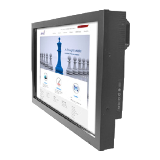
- Page 1 User’s Manual - Model #VH-CH6504-QF35L0-0000R-MIL WINSONIC ELECTRONICS Co., LTD No.290-1, Wen Chung Rd., Taoyuan City, Taiwan, R.O.C l:+886-3-3704789 ax:+886-3-3704722 E-mail:sales@ewinsonic.com www.ewinsonic.com...
-
Page 2: Table Of Contents
Contents Safety Instruction Product Installation Panel Specification General Description Optical Specifications Absolute Maximum Ratings Backlight Unit Reliability AD Board Specification Trouble Shooting... -
Page 3: Safety Instruction
Safety Instruction Read and follow these instructions when connecting and using your LCD monitor: Operation: 1. Keep the monitor out of direct sunlight and away from stoves or any other heat source. 2. Remove any object that could fall into ventilation holes or prevent proper cooling of the monitor's electronics. -
Page 4: Product Installation
Product Installation 1. Switch off the power on both your monitor and your computer. The Power Switch is located in the right of the monitor. 2. Connect the power cord to the AC outlet, and connect the power to the monitor through the AC/DC adapter. -
Page 5: Panel Specification
2 General Description This specification applies to the 65 inch Color TFT-LCD Module P650QVF03.0. This LCD module has a TFT active matrix type liquid crystal panel 3840x2160 pixels. This module supports 3840x2160 mode. Each pixel is divided into Red, Green and Blue sub-pixels or dots which are arranged in vertical stripes. Gray scale or the brightness of the sub-pixel color is determined with a 10-bit gray scale signal for each dot. - Page 6 2. Absolute Maximum Ratings The followings are maximum values which, if exceeded, may cause faulty operation or damage to the unit Item Symbol Unit Conditions Logic/LCD Drive Voltage -0.3 [Volt] Note 1 Input Voltage of Signal -0.3 [Volt] Note 1 Operating Temperature Note 2 Operating Humidity...
-
Page 7: Optical Specifications
3. Electrical Specification The P650QVF03.0 requires two power inputs. One is employed to power the LCD electronics and to drive the TFT array and liquid crystal. The other is to power Back Light Unit. 3.1. Electrical Characteristics 3.1.1 Input Power Item Symbol Min. - Page 8 Note3. Measurement condition : Rising time = 400us s ...
- Page 9 3.2 input Connections LCD connector: (JAE) SJ11346-FI-RTE51SZ-HF Symbol Description Note PIN Symbol Description Note Vx1 LOCK 12V_PW LCOKN Ground 12V_PW Vx1 lane 0 12V_PW RxN0 Vx1 lane 0 12V_PW RxP0 Ground 12V_PW 12V_PW RxN1 Vx1 lane 1 Vx1 lane 1 12V_PW RxP1 12V_PW...
- Page 10 3.3 Input Data Format 3.3.1 V by one Data mapping 30bpp RGB Packer input & Unpacker Mode /YCbCr444 output (10bit) D[0] R/Cr[2] D[1] R/Cr[3] D[2] R/Cr[4] D[3] R/Cr[5] Byte0 D[4] R/Cr[6] D[5] R/Cr[7] D[6] R/Cr[8] D[7] R/Cr[9] D[8] G/Y[2] D[9] G/Y[3] D[10] G/Y[4]...
- Page 11 3.3.2 Color Input Data Reference The brightness of each primary color (red, green and blue) is based on the 10 bit gray scale data input for the color; the higher the binary input, the brighter the color. The table below provides a reference for color versus data input. COLOR DATA REFERENCE Input Color Data GREEN...
- Page 12 3.4 Signal Timing Specification 3.4.1 Input Timing This is the signal timing required at the input of the user connector. All of the interface signal timing should be satisfied with the following specifications for its proper operation. 3.4.1.1 Timing table Timing Table (DE only Mode) 60Hz Signal...
- Page 13 48Hz Signal Item Symbol Min. Typ. Unit Period 2200 2252 2360 Vertical Section Active Tdisp (v) 2160 Blanking Tblk (v) Period Tclk Horizontal Section Active Tdisp (h) Blanking Tblk (h) Tclk Clock Frequency Fclk=1/Tclk 73.359 74.250 75.092 Vertical Frequency Frequency 47.99 Horizontal Frequency Frequency...
-
Page 14: Absolute Maximum Ratings
3.4.1.2 Signal Timing Waveforms The timing diagrams of the input timing (Lane1~8 V-by one data:1, 2, 3, 4, 1921, 1922, 1923, 1924) N Line... - Page 15 Note1. Display position is specific by the rise of DE signal only. Horizontal display position is specified by the rising edge of 1 DCLK after the rise of 1 DE, is displayed on the left edge of the screen. Note2.Vertical display position is specified by the rise of DE after a “Low” level period equivalent to eight times of horizontal period.
- Page 16 Note : 1. V-by-one Signal diagram LOCK LOCKN RRIP VRXINP /N CDR and ALN Training Normal Pattern Normal Pattern 2. Receiver Clock SSCG (Spread spectrum clock generator) is defined as below figures. Fclk_ss(max) Fclk Fclk_ss(min) 3. V-by-one Intra-pair Skew VRXIN1_P VRXIN1_N INTRA INTRA...
- Page 17 Eye Mask Example of Eye diagram...
- Page 18 3.4.3 Power Sequence for LCD Parameter Min. Typ. Unit 1000 Note: (1) t4=0 : concern for residual pattern before BLU turn off. (2) t6 : voltage of VDD must decay smoothly after power-off. (customer system decide this value) (3) When the power supply input voltage(VDD) is off, be sure to pull down the valid and the invalid data to 0V.
- Page 19 Backlight Specification 3.5.1 Electrical specification Spec Item Symbol Condition Unit Note Input Voltage VDDB 22.8 25.2 Input Current VDDB=24V 10.5 12.6 Input Power VDDB=24V Inrush Current VDDB=24V 12.5 RUSH On/off control voltage VDDB=24V BLON On/Off control current VDDB=24V BLON VDDB=24V External PWM V_EPWM Control Voltage...
- Page 20 3.5.2 Input Pin Assignment LED DB connector: CI0114M1HRL-NH(CviLux) or equivalent CI0112M1HRL-NH(CviLux) or equivalent Symbol Description Note VDDB Power Supply Input Voltage VDDB Power Supply Input Voltage VDDB Power Supply Input Voltage VDDB Power Supply Input Voltage VDDB Power Supply Input Voltage Ground Ground Ground...
- Page 21 Symbol Description Note VDDB Power Supply Input Voltage VDDB Power Supply Input Voltage VDDB Power Supply Input Voltage VDDB Power Supply Input Voltage VDDB Power Supply Input Voltage Ground Ground Ground Ground Ground Note1. DET status BLU status 0 ~ 0.8V Normal Open collector Abnormal...
-
Page 22: Backlight Unit
Note5. PDIM PWM Dimming range: Control 100% range External PWM 100% Dimming 100% Performance guaranteed dimming range: 0%, 5~100% IF External PWM function less than 5% dimming ratio, Judge condition as below: (1)Backlight module must be lighted ON normally. (2)All protection function must work normally. (3)Uniformity and flicker could not be guaranteed... - Page 23 3.5.3 Power Sequence for Backlight 24V(typ.) 24V(typ.) Power Input for BLU Power Input for BLU (VDDB) Valid Dimming Control Signal (V_IPWM,V_EPWM) BLU On/Off Enable (VBLON) Local dimming Enable *3*4 Dip condition Power Input for BLU Power Input for BLU (VDDB) (VDDB) VDDB(typ .)*0.8 VDDB(typ .)*0.8...
- Page 24 3.5.4 LED Operating Life Time Value Parameter Symbol Unit Note Min. Typ. Backlight Operating Life Time(MTTF) 50000 60000 Hour Note: 1. The lifetime (MTTF) is defined as the time which luminance of LED is 50% compared to its original value. [Operating condition: Continuous operating at Ta = 25±2℃, for single lamp/LED only]...
-
Page 25: Ad Board Specification
General Function A. Large size TFT-LCD module drive board resolution up to 4096x2160 B. VGA input C. DisplayPort1.2 input D. DVI Connector input E. Five HDMI input (One HDMI 2.0 and Four HDMI 1.4/MHL2.0) F. Support non-linear scaling from 4:3 to 16:9 or 16:9 to 4;3 G. - Page 26 Connect Function Reference Description Connector Type 12V DC Power input connector for a DC Jack Audio Input: VGA Signal Audio Input Audio Output: Audio Signal Output VGA 1 VGA Input : VGA Signal Input DVI 1 DVI Input: DVI Signal Input DP 1 Display Port : Display Port Signal Input (DP1.2) HDMI1...
- Page 27 LCD monitor GTR73 OSD operation 1. Main Menu : If push the “ MENU” key the screen will appear this main menu page, you can use the “UP” or“ADJ. +” AND “Down” or “ADJ. –“ key ( Shown in Pic1 ) to select the function you need.
-
Page 28: Reliability
b. Display Function Display Rotate, Set to rotate the OSD menu OSD Rotated: OFF / 90 / 270 c. Picture b-1 Backlight If select BackLight function, you can push ADJ+ or ADJ- key to increase or decrease backlight current of the inverter. BackLight... - Page 29 c-2. Brightness If select Brightness function, you can push ADJ+ or ADJ- key to increase or decrease offset setting. Brightness c-3.Contrast < > Adjusts the image CONTRAST in relationship to the background. Press“ ” or “ ” to adjust. Contrast c-4.
- Page 30 d. Analog Select Screen Setting function , that will into the sub-page to adjust display’s function of the picture. d-1. Auto Adjust Select this function on OSD MAIN MENU and push the MENU key. In this function, that will be activated the auto adjusting for the picture. Auto Adjust d-2.
- Page 31 d-3. V-Position If select V Position function, you can push ADJ+ or ADJ- key to shift to Up or Down of the picture. V-Position d-4. Clock If select Clock function,you can push ADJ+ or ADJ- key to increase or decrease video H Size of the picture.
- Page 32 f. Advance If your monitor does not operate normally or cannot be turned on, please check the following troubleshooting questions. Remember also to check any other connected electronic device, such as DVD or Blu-ray player to pinpoint the problem. f-1. Aspect Ratio: Adjust the Aspect Ratio settings in the SETUP menu or press the ASPECT button on the remote control.
-
Page 33: Trouble Shooting
Trouble Shooting If your monitor fails to operate correctly, consult the following chart for possible solution before calling for repairs/RMA. Condition Possible Solution The screen is not synchronized? 1. Check if the signal cable is firmly seated in the socket. 2.
Need help?
Do you have a question about the VH-CH6504-QF35L0-0000R-MIL and is the answer not in the manual?
Questions and answers