Table of Contents
Advertisement
Advertisement
Table of Contents

Related Manuals for GRASS GRASS ECOPRESS


Summary of Contents for GRASS GRASS ECOPRESS
- Page 1 GRASS ECOPRESS Ecopress-Pneumatic / Ecopress-Manual The star in your cabinet...
- Page 2 Technical Data Technical Data Dimensions: Width of machine table Depth of machine table with bore distance 20 mm Height of machine table Total height of machine Total depth of machine Other data: Press force of 0,6 MPa ( 6 bar ) about 2800 Weights: Total weight of the Ecopress-Pneumatic standard equipment...
-
Page 3: Table Of Contents
Table of contents Page 1. General information 1-001 List of illustrations 1-002 Manufacturer 1-003 Copyright 1-004 Terms of guarantee 2. Safety Information 2-001 Safety information 2-002 Recommended usage 2-003 Risks according to EN 292-2 2-004 Safety devices 2-005 Description of stickers 2-006 Dangers and safety measures 3. - Page 4 7-403 Drilling the hole line borings ( only with accessories ) 54-55 7-404 Drilling the fronts for Grass Zarge System 6000/7000 56-57 7-405 Drilling the back panels for Grass Zarge System 6000/7000 ( only with accessories ) 58-59 7-406 Drilling and inserting visible hinges...
-
Page 5: General Information
Operating the stop adjustment gauge 7-308-01 Operating the index ruler 7-309-01 Adjusting the pneumatic hold down clamps 7-401-01/02 Drilling and inserting the Grass hinges 7-402-01/02 Drilling and inserting the Grass baseplates 7-403-01/02 Drilling the hole line borings 7-404-01/02 Drilling the fronts... -
Page 6: 1-002 Manufacturer
The manufacturer is under no obligation to modify machines free of charge due to changed regulations, standards or specifications. In case of guarantee claims, please contact the authorized Grass representative or an authorized Grass distributor and give him the machine model and the machine number. -
Page 7: Safety Information
2-002 Recommended Usage - The Grass Ecopress hinge drilling machine is used exclusively for drilling in solid wood and derived wood materi als as well as for the purposes described in chapter 7-4 ”Examples of Usage”. Other uses are not specified, and, thus, the manufacturer is not liable for resulting damages. - Page 8 2. Safety Information 2-003 Risks According to EN 292-2 The Ecopress hinge drilling machine is built according to current state of technology and known safety and technical directives. Still, risks remain for the life and health of the operator or of third parties, as well as damage to the machine and other property.
-
Page 9: 2-006 Dangers And Safety Measures
Tool releases chuck with clamping screw Tool breaks use exclusively authorized products (for example, from the Grass GmbH product line) Contact with tool all tools are behind transparent covers Tool - Contact with the machine safety - drilling depth stop... -
Page 10: Product Description
Hook-up line are to be very inflammable If an electric coupling is required for the suction system, the Grass company has a special accessory-a volume flow monitor with the appropriate contacts which are connected as shown in the electrical wiring diagram in chapter 4-007. -
Page 11: 3-002 Usage
3. Product Description 3-002 Usage The Ecopress hinge drilling machine is designed exclusively for only those operations described in chapter 7.4 ”Examples of Usage”. The manufacturer guarantees a very smooth and problem free operation for these usages. Violations or misuse can result in injuries of the machine operators or to damages to the machine or workpieces. 3-003 Product Identification All machine are provided with an identificaiton plate on which the machine number, manufacturing year, machine style, voltage and frequency, as well as the required pneumatic pressure, are listed. - Page 12 3. Product Description Illustrations of Accessories Side stop left Right 10/13/15 mm Center 0-point gauge Stop pin Pendulum stop Adjustment setting gauge Pneumatik hold down device Insertion die for different hinges Insertion die for different base plattes Drill-bits Extension bar 5-spindle gear box The star in your cabinet...
-
Page 13: 3-006 Standard Accessories
3. Product Description 3-006 Standard Accessories Description Article Nr: Side stop, left, with 10 mm latch ( standard ) 89610 Side stop, right, with 10 mm latch ( standard ) 89510 Side stop, right, with 13 mm latch (for Zarge front system 6000) 90520 Side stop, right, with 15 mm latch (for Zarge front system 7000) 92045... -
Page 14: Maschine - Parts Description
4. Machine-Parts Description Ilustration 4-001-01 Illustration 4-001-02 The star in your cabinet... -
Page 15: Overall View Of The Ecopress-Pneumatic
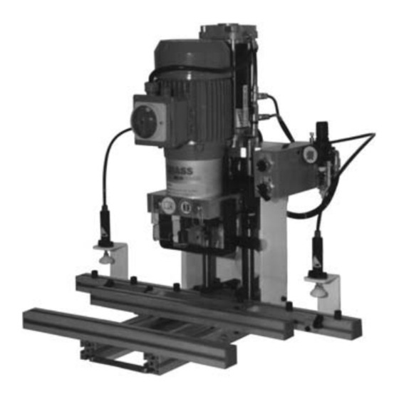
4. Machine-Parts Description 4-001-1 Overview of Ecopress-Pneumatic with Assembly Group Numbering Illustration 4-001-01 Machine table with fence and side stops; pendulum stop and pneumatic hold down clamp devices are accessories Machine frame Motor support with electric motor, gearbox and insertion arm into which the insert dies are placed Electrical switch box on the back side of the machine Control panel Pneumatic cylinder... - Page 16 4. Machine-Parts Description Illustration 4-002-01 Illustration 4-002-02 The star in your cabinet...
-
Page 17: 4-002 Description Of The Individual Assembly Groups
4. Machine-Parts Description 4-002 Description of the Individual Assembly Groups Machine Table Illustration 4-002-01 Table base Support strip, front Support strip, back Fence, 720 mm long Stop on ruler Side stop, left Side stop, right Clamping lever for adjusting the depth of the fence (both sides ) Depth stop scale for drilling distance Accessories, not included in standard equipment Zero point for stop adjustment gauge... - Page 18 4. Machine-Parts Description Illustration 4-002-03 Illustration 4-002-04 The star in your cabinet...
-
Page 19: Machine Frame Of The Ecopress-Pneumatic
4. Machine-Parts Description 4-002 Description of the Individual Assembly Groups Machine frame of the Ecopress-Pneumatic Illustration 4-002-03 Right frame plate Outflow device for condensation water Pneumatic feed line Regulating knob for pneumatic adjustment. Lift the knob to adjust. Turn clockwise to increase the pressure. - Page 20 4. Machine-Parts Description Illustration 4-002-05 Illustration 4-002-06 The star in your cabinet...
-
Page 21: Electrical Switch Box Of The Ecopress-Pneumatic
4. Machine-Parts Description 4-002 Description of the Individual Assembly Groups Electrical Switch Box of Ecopress-Pneumatic Illustration 4-002-05 Lead cable 5 x 1.5 mm Thermal excess current release Electric safety feature (fuse) for control circuit; reserve fuse in switch box cover Power contactor switches the motor on Cable to the electric motor P-E-transformer switches on the power contactor and, therewith, the motor... - Page 22 4. Machine-Parts Description Illustration 4-003-01 Illustration 4-003-02 The star in your cabinet...
-
Page 23: Hole Line Boring - Standard Gear Box
- Bore holes for dowel baseplates with dowel distance of 32 mm - Bore holes for drawer front with a distance of 32 or 64 mm for the Grass-Zarge system 6000/7000 - Bore holes for drawer back panels for Grass Zarge system 6000/7000... - Page 24 4. Machine-Parts Description Illustration 4-004-01 Illustration 4-004-02 The star in your cabinet...
-
Page 25: Operating Features Of The Ecopress-Pneumatic
4. Machine-Parts Description 4-004 Description of the Operating Features Ecopress-Pneumatic llustration 4-004-01 Start button for the stroke motion As long as the start button is activated, the bore head moves downward until the boring depth stop (position 4, illustration 4-002-02) sets on the workpiece,that is, until the pneumatic cylinder has completed the stroke motion. - Page 26 4. Machine-Parts Description Einstellung: 0,55 - 0,6 MPa 5,5-6 bar max 10 bar Illustration 4-006-01 The star in your cabinet...
-
Page 27: Pneumatic Wiring Diagram For The Ecopress-Pneumatic
4. Machine-Parts Description 4-006 Pneumatic Wiring Diagram of the Ecopress-Pneumatic Illustration 4-006-01 Pos. Type Description Function 1 Hörbiger MKS-08 H Filter-pressure reducer 1/4” Pressure regulator and filter unit including pneumatic air gauge 2 Festo SV5-M5B 5/2-type valve M5 Start valve for boring and Festo T-22-S press button insertion cycle... - Page 28 4. Machine-Parts Description Elektroschrank 11 MOBRF R11 Illustration 7-407-01 The star in your cabinet...
-
Page 29: Electric Wiring Diagram
S2 available only with Ecopress-Manual S3, if required is availble from Grass as an accessory. In position S3, a direct connection of x1 to x2 is available in the electric switch box. Should an electric volume flow monitor be added, it should be connected to x1 and x2. -
Page 30: Shipping And Installation Of Machines
5. Shipping and Installation of Machines Illustration 5-003-01 Illustration 5-003-02 Illustration 5-003-03 Illustration 5-003-04 The star in your cabinet... -
Page 31: 5-002 Space And Environmental Requirements
5. Shipping and Installation of Machines 5-001 Transportation and Storage Requirements The Ecopress will be delivered packaged in a box. The machine is partially assembled. Protect the packaged machine against humidity and moisture during transportation and storage. Storage temperature range is from -20°C to +50°C 5-002 Space and Environmental Requirements The necessary space required depends on the size of the workpieces to be processed. -
Page 32: Start-Up
6. Start-Up Illustration 5-003-05 Illustration 5-003-06 Illustration 5-003-07 Illustration 5-003-08 Illustration 5-003-09 Illustration 5-003-10 The star in your cabinet... -
Page 33: 6-001 Pneumatic Connection
6. Start-Up 6-001 Pneumatic Connection (Only With Ecopress Pneumatic) The Ecopress is equipped with a factory provided 2 m long airhose (6/3 diameter). A Euro quick coupling will be installed, according to the country of destination. For wiring diagram, see chapter 4-006, page 26. Connection: Caution: If the machine is connected to pressure, the motor support with the gearbox can move up. - Page 34 7. Operating the Unipress/Unipress Illustration 7-201-01 Illustration 7-202-01 Illustration 7-202-02 The star in your cabinet...
-
Page 35: Operating The Ecopress
7. Operating the Ecopress 7-1 Requirements for Operators This machine must only be operated by trained persons who are familiar with handling the machine. This knowledge may be obtained by studying the operating instructions thoroughly or by hands-on training by a specialist. The operators must be physically able to operate the machine. - Page 36 7. Operating the Ecopress Illustration 7-203-01 Illustration 7-203-02 Illustration 7-203-03 Illustration 7-203-04 Illustration 7-203-05 Illustration 7-203-06 The star in your cabinet...
-
Page 37: Operating The Ecopress
7. Operating the Ecopress 7-2 Setting Up the Ecopress 7-203 Installing the 5-Spindle Hole Line Boring Gearbox (accessory) Illustrations 7-203-01/02/03/04/05/06 Tools Needed: Allen wrench 3 mm Allen wrench 5 mm - Turn off the main switch. - Take off the plastic cover of the gearbox. - Remove all drill bits which are in the gearbox, including all of the fastening screws, according to chapter 7-201 - Mount the 5-spindle hole line boring gearbox, noting the position of the drill chucks and the position of the coupling of the 5-spindle hole line boring gearbox. - Page 38 7. Operating the Ecopress Illustration 7-204-01 Illustration 7-204-02 Illustration 7-204-03 Illustration 7-204-04 Illustration 7-204-05 Illustration 7-204-06 The star in your cabinet...
-
Page 39: Mounting The Pendulum Stop
7-204-04, so that the same dimensions are legible at position 8 (illustration 7-204-03) and at position 9 (illustration 7-204-04). Dimension = 10 mm for back panels for Grass Nova Zarge (System 7000 ) Dimension = 12 mm for back panels for Grass Zarge System 6000 - Illustration 7-204-05/06 right back panel stop / left bore hole for Zarge 6036 with boring distances laterally of 12 mm und depth of 37.5 mm... - Page 40 7. Operating the Ecopress Illustration 7-301-01 Illustration 7-302-01 The star in your cabinet...
-
Page 41: Adjusting The Ecopress
7. Operating the Ecopress 7-3 Adjusting the Ecopress 7-301 Adjusting the Boring Depth Illustration 7-301-01 Tools needed: Allen wrench 3 mm - Loosen the set screw (1) with the 3 mm Allen wrench - Turn the operating control (2) clockwise ( the adjusting control moves downward over the thread ). The boring depth is decreased about 1 mm for each rotation. - Page 42 7. Operating the Ecopress Illustration 7-303-01 Illustration 7-304-01 The star in your cabinet...
-
Page 43: 7-303 Adjusting The Boring Speed Of The Ecopress-Pneumatic
7. Operating the Ecopress 7-3 Adjusting the Ecopress 7-303 Adjusting the Boring Speed of the Ecopress-Pneumatic of the Ecopress-Pneumatic Illustration 7-303-01 Tools needed: Allen wrench 3 mm The Ecopress operates with a fixed feeding speed and a continously adjustable operating speed. When starting the switch cam (illustration 7-304-01, position 1) on the pneumatic valve (illustration 7-304-01, position 2), the switchover from the feeding speed to the operating speed is completed. - Page 44 7. Operating the Ecopress illustration 7-305-01 illustration 7-306-01 The star in your cabinet...
-
Page 45: Adjusting The Turn-On Time Of The E-Motor With The Ecopress-Manual
7. Operating the Ecopress 7-3 Adjusting the Ecopress 7-305 Adjusting the Turn-On Timing of the Electric Motor of the Ecopress-Manual Illustration 7-305-01 Tools needed: Allen wrench 3 mm As soon as the switch cam (1) activates the roller of the roller limit switch (2), the electric motor turns on. The switch cam, and therefore, the turn-on timing of the motor can be adjusted by loosening the clamping screw (3). - Page 46 7. Operating the Ecopress Illustration 7-307-01 Illustration 7-307-02 Illustration 7-307-03 The star in your cabinet...
-
Page 47: 7-307 Operating The Stop Adjustment Gauge
7. Operating the Ecopress 7-3 Adjusting the Ecopress 7-307 Operating the Stop Adjustment Gauge (Accessory) Illustration 7-307-01/02/03 Tools needed: Open end fork wrench 8/10 mm Center-zero point gauge is an accessory. Stop adjustment gauge is an accessory. - After adjusting the side stops on the right side, the adjustment of the left side is made (for example, for left and right door at the hinge mounting). - Page 48 7. Operating the Ecopress Illustration 7-308-01 Illustration 7-309-01 The star in your cabinet...
-
Page 49: 7-308 Operating The Index Ruler ( Accessory)
7. Operating the Ecopress 7-3 Adjusting the Ecopress 7-308 Operating the Index Ruler For Hole Line Borings (accessory) Illustration 7-308-01 Tools needed: Open end fork wrench 8/10 mm 5-Spindle gear box is an accessory Index ruler is an accessory The index ruler is used to set the distances between the individual side stops in 32 mm distanced notches for the hole line borings. - Page 50 7. Operating the Ecopress Illustration 7-401-01 Illustration 7-401-02 The star in your cabinet...
-
Page 51: 7-401 Drilling And Inserting The Grass Hinge System 1000/3000/4000
7. Operating the Ecopress 7-401 Drilling and Inserting the Grass Hinge System 1000/3000/4000 Illustrations 7-401-01/02 Required Equipment: - 1 drill bit, diameter Ø 35 mm, right - cup bore hole - 2 drill bit, diameter, Ø 8 mm, left - dowel bore hole... - Page 52 7. Operating the Ecopress Illustration 7-402-01 Illustration 7-402-01 The star in your cabinet...
-
Page 53: 7-402 Drilling And Inserting The Grass Baseplate System 1000/3000
7. Operating the Ecopress 7-402 Drilling and inserting the Grass Baseplate System 1000/3000 Illustration 7-402-01/02 Required Equipment: - 1 drill bit, diameter, Ø 10 mm, right - dowel bore hole - 2 drill bit, diameter, Ø 10 mm, left - dowel bore hole... - Page 54 7. Operating the Ecopress Illustration 7-403-01 Illustration 7-403-02 The star in your cabinet...
-
Page 55: Drilling The Hole Line Borings
7. Operating the Ecopress 7-403 Drilling the Line Hole Borings (only with accessories) Illustration 7-403-01/02 Required Equipment: - 3 drill bit, diameter, Ø 5 (3) mm, right - (black drill bit on black marking) - 2 drill bit, diameter, Ø 5 (3) mm, left - (red drill bit on red marking) - 1 5-spindle line hole gearbox (accessory) Machine Set-Up: - Turn off the main switch on the motor... - Page 56 7. Operating the Ecopress Illustration 7-404-01 Illustration 7-404-02 The star in your cabinet...
-
Page 57: 7-404 Drilling The Fronts For Grass Zarge System 6000/7000
7. Operating the Ecopress 7-404 Drilling the Front for Grass Zarge System 6000/7000 Illustration 7-404-01/02 Required Equipment: - 2 (1) drill bit, diameter, Ø 10 mm, right - (1) drill bit, diameter, Ø 10 mm, left - Clamping capacity for 32 mm hole distance... - Page 58 7. Operating the Ecopress Illustration 7-405-01 Illustration 7-405-02 The star in your cabinet...
-
Page 59: 7-405 Drilling The Back Panels For Grass Zarge System 6000/7000 ( Only With Accessories )
7. Operating the Ecopress 7-405 Drilling the Back Panels for Grass Zarge System 6000/7000 Illustration 7-405-01/02 Required Equipment: - 1 drill bit, diameter, Ø 10 mm, right - for back panels with System 6000 - 1 drill bit, diameter, Ø 10 mm, left - for back panels with System 7000... - Page 60 7. Operating the Ecopress Illustration 7-406-01 Illustration 7-406-02 The star in your cabinet...
-
Page 61: 7-406 Drilling And Inserting Visible Hinges
7. Operating the Ecopress 7-406 Drilling and Inserting Visible Hinges Illustration 7-406-01/02 Required Equipment: - 1 drill bit, diameter, Ø 35 mm, right -cup bore hole - 2 drill bit, diameter, Ø 8 mm, left - dowel bore hole - 1 insertion die corresponding to hinge Machine Set-Up: - Turn off the main switch on the motor - Take off the gearbox cover. - Page 62 7. Operating the Ecopress Illustration 7-407-01 Illustration 7-407-02 The star in your cabinet...
-
Page 63: 7-407 Drilling And Inserting Fastening Hardware
7. Operating the Ecopress 7-407 Drilling and Inserting Fastening Hardware Illustration 7-407-01/02 Required Equipment: - 1 drill bit, diameter, Ø 20 mm, right - cup bore hole - 1 drill bit, diameter, Ø 10 mm, left - dowel bore hole - 1 insertion die corresponding to hinge Machine Set-Up: - Turn off the main switch on the motor... - Page 64 7. Operating the Ecopress Illustration 7-408-01 Illustration 7-408-02 The star in your cabinet...
-
Page 65: Drilling Of Handle Bore Holes
7. Operating the Ecopress 7-408 Drill of Handle Bore Holes (Only with accessories) Illustration 7-408-01/02 Required Equipment: - 2 (1) drill bit, diameter, Ø 5 (3) mm, right - (1) drill bit, diameter, Ø 5 (3) mm, left - 1 5-spindle line hole gearbox (accessory) - 1 piece wooden base, about 5 mm thick Machine Set-Up: - Turn off the main switch on the motor... -
Page 66: Trouble Shooting And Problem Solving
8. Trouble Shooting and Problem Solving Illustration 8-001-01 The star in your cabinet... -
Page 67: 8-003 Motor Does Not Run
8. Trouble Shooting and Problem Solving 8-001 Incorrect Drilling Distance — Adjustment of Scale Illustration 8-001-01 - Turn off the main switch - Take off the gearbox cover. - Remove all existing drill bits, including fastening screws, from the gearbox. - Fasten a drill bit on the hinge cup drill-spindle - Gearbox placement, see illustration 7-401-01. - Page 68 8. Trouble Shooting and Problem Solving Illustration 8-005-01 Illustration 8-005-02 The star in your cabinet...
-
Page 69: 8-004 Boring Head Does Not Descend
8. Trouble Shooting and Problem Solving 8-004 The Boring Head Does Not Descend only with the Ecopress-Pneumatic - Turn off the main switch. - Check the pneumatic lead cable. - Check the air pressure in the machine with the pneumatic gauge; it should indicate 5.5 - 6 bar. - Check if all the pneumatic lines inside the Ecopress are plugged in and if the pneumatic lines are damaged. -
Page 70: Maintenance And Care
The Ecopress has proved its durability in many fatigue tests. But in order to ensure many years of smooth and problem-free operation for your Ecopress, we recommend having the machine serviced every 1 to 3 years by an experienced Grass Customer Service Technician or by a trained Grass Distributor. 9-002 Maintenance and Care Information The machine should only be cleaned after the main switch is turned off to 0 on the electric motor and the machine is disconnected from the pneumatic air ductwork system. -
Page 71: Miscellaneous
Machine and Steel Construction Industry. Any warranty claims are voided in cases where there is misuse, unauthorized repairs, use of non-Grass or unauthorized spare parts, as well as use of non-Grass or unauthorized accessories without the express written consent of Grass GmbH. We reserve the right to make technical modifications for whatever reasons we deem necessary. - Page 72 Grass GmbH Grass Platz 1 A-6973 Höchst Austria From: ..........................................The star in your cabinet...
- Page 73 10. Miscellaneous 10-002 Disposal Form Buyer: Name:..........Street........…..Zip Code:........…..City:..........Country:..........Telephone number:......Fax number:..........Machine: Model:....................Machine number:..............…..Voltage / Frequency according to the identification plate:..........Pneumatically operated...…….. Operated with hand lever...……. General: The buyer hereby confirms that the machine has been disposed of properly. The machine consists of the following materials: Steel / iron parts: machine frame, various gearbox components...
- Page 74 Grass GmbH Grass Platz 1 A-6973 Höchst Austria From: ..........................................The star in your cabinet...
- Page 75 10. Miscellaneous 10-003 Resale Form Seller: Name:.......……………..... Street......……………....Zip Code:......………………... City:...........………..Country:........……….…... Telephone number:.......... Fax number:..........Reason for selling the machine: ....................................................................................................................................................................................................................................…………………………………………………………………………………………………..Buyer: Name:........……………..Street........………..……..Zip Code:......………………..City:......……..…....Country:.........…………... Telephone number:.......... Fax number:..........After reselling the machine, please return the completed resale form to the manufacturer. The buyer agrees to store the data in an electronic data processing system.
- Page 76 Grass GmbH Grass Platz 1 A-6973 Höchst Austria From: ..........................................The star in your cabinet...
- Page 77 What were your reasons for choosing Ecopress over the competitor’s machines? Price Versatility of the machine Appearance Wide range of accessories Quality Loyal Grass customer Price / performance ratio Grass processor Durability of the machine How did you find out about the Ecopress? Magazine advertisement...
- Page 78 Grass GmbH Grass Platz 1 A-6973 Höchst Austria From: ..........................................The star in your cabinet...
-
Page 79: 10-005 Questionnaire
10. Miscellaneous 10-005 Questionnaire 2: Customer Satisfaction Buyer: Name:........………….... Street.......…………….... Zip Code:.........……………..City:........……….... Country:........…………..Telephone number:......... Fax number:..........How do you rate your satisfaction with the machine? * Ecopress-Pneumatic Ecopress-Manual with Hand Lever Very good Fair Good Not at all Would you buy this machine again?* because the machine meets the requirements because there are better machines available... - Page 80 Grass GmbH Grass Platz 1 A-6973 Höchst Austria From: ..........................................The star in your cabinet...
- Page 81 Note The star in your cabinet...
- Page 82 REPRESENTATIVES AROUND THE WORLD Austria Europe Greece GRASS GmbH Baltic States D. Gallidis & Co Grass Platz 1, A-6973 Höchst AS Savo D&T Leoforos Kallitheas 29 Tel. (05578) 701-0 Rebase 16 GR-56123 Thessaloniki Fax (05578) 701-59 EE-51013 Tartu Tel. (031) 74 33 48 e-mail: info@grass.at...
- Page 83 Switzerland Hong Kong Sales: GRASS GmbH Ming Tat Hong Syria Grass Platz 1, A-6973 Höchst Hardware Supplier Co., Ltd. M. RIAD KANNOUS Tel. +43 / 5578 / 701-0 Room 03, 6/F., Kinglet Industrial Building Manakhlia Str. Fax +43 / 5578 / 701-59 21-23 Shing Wan Road, Tai Wai, Shatin P.O.Box 36587, Damascus...
- Page 84 The star in your cabinet Grass GmbH A-6973 Hoechst, Grass Platz 1 †!ƒö>,|:|>öö!4ö.ä Tel. +43 / (0) 55 78 / 701-0, Fax +43 / (0) 55 78 / 701-59 (01)99003012922692(30)000001(20)00 Internet: www.grass.at, e-mail: info@grass.at...
Need help?
Do you have a question about the GRASS ECOPRESS and is the answer not in the manual?
Questions and answers
How to remove the gear box for repair
To remove the gearbox on a GRASS ECOPRESS for repair, follow these steps:
1. Turn off the main switch.
2. Take off the plastic cover of the gearbox.
3. Remove all drill bits from the gearbox, including all fastening screws (refer to chapter 7-201).
4. The gearbox can now be removed for repair.
This answer is automatically generated