Table of Contents
Advertisement
Quick Links
Request for the Customers
•
Read and understand this operating manual before using the pyrolyzer unit.
•
You must operate the pyrolyzer unit in accordance with the operating manual.
•
Regardless of warranty period, we shall not make any compensation for accidents and
damage caused by using this product.
The compensation shall be made only under the warranty policy of products or parts
replacement.
•
Because this is a safety unit, a regular maintenance for every six months and daily
maintenance must be performed.
•
If you find abnormalities in the pyrolyzer unit, please notify them to our local representative
immediately.
1.800.561.8187
Pyrolyzer Unit
(for GD-70D Series)
PLU-70
Operating Manual
www.
information@itm.com
.com
PT9E-0070
Advertisement
Table of Contents

Related Manuals for Riken Keiki PLU-70


Summary of Contents for Riken Keiki PLU-70
- Page 1 PT9E-0070 Pyrolyzer Unit (for GD-70D Series) PLU-70 Operating Manual Request for the Customers • Read and understand this operating manual before using the pyrolyzer unit. • You must operate the pyrolyzer unit in accordance with the operating manual. • Regardless of warranty period, we shall not make any compensation for accidents and damage caused by using this product.
-
Page 2: Preface
Preface Preface Thank you for choosing the pyrolyzer unit PLU-70 designed for dedicated use with our gas detector head GD-70D series. Please check that the model number of the product you purchased is included in the specifications on this manual. -
Page 3: Table Of Contents
<Contents> Preface ........................Important Notices on Safety ..................Overview ......................... 1-1. Product components....................1-2. Product specifications....................1-3. List of accessories ....................1-4. Names and functions for each part................1-5. Block diagram......................Installation ....................... 2-1. Requirements ......................2-2. Installation of pyrolyzer unit ..................2-3. -
Page 4: Important Notices On Safety
Important Notices on Safety Important Notices on Safety <Definition of DANGER, WARNING, CAUTION, and NOTE> DANGER Indicates an imminently hazardous situation which, if not avoided, will result in death or serious injury or serious damage to the product. The use of this symbol is to be limited to the most extreme situation. WARNING Indicates a potentially hazardous situation which, if not avoided, could result in death or serious injury on the human body or object. - Page 5 Important Notices on Safety <Precautions> CAUTION Do not use a transceiver (walkie-talkie) near the pyrolyzer unit. Radio wave from a transceiver near the pyrolyzer unit or its cables may affect reading. When using a transceiver, it must be used in a place where it disturbs nothing. To restart the pyrolyzer unit, you must wait five seconds more before doing it.
-
Page 6: Overview
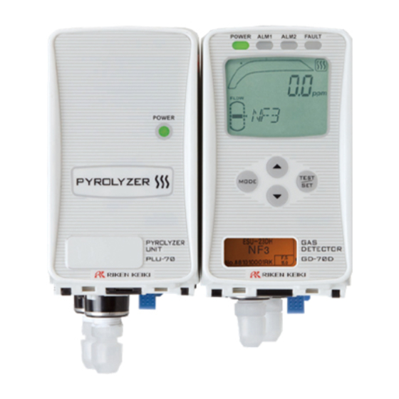
1 Overview 1-1. Product components Overview 1-1. Product components <Pyrolyzer Unit (PLU-70)> <Standard Accessories> • Operating manual • Protective rubber cap (to be removed when using the pyrolyzer unit) • Dedicated handling lever (for wiring) • Dedicated U-tube <Gas Detector Head GD-70D Series (Base Unit: Option)>... -
Page 7: Product Specifications
1 Overview 1-2. Product specifications 1-2. Product specifications Power Display POWER lamp on (green) Recommended Cable of CVV, etc.(1.25sq) - 2-core Power Cable 24VDC ±10% Power Supply Power Max. 25 W consumption Tube Connecting Rc1/4 (O.D Φ6-1t half-union for Teflon tube<PP>supplied) Hole Operating 0-40°C (at a constant condition) -
Page 8: Names And Functions For Each Part
1 Overview 1-4. Names and functions for each part 1-4. Names and functions for each part <Appearance> M5 mounting hole Fan exhaust hole Power lamp GAS IN Protective cover for power switch Power switch Screw for grounding earth rod GD-70D connecting tube External wire hole Connector for PoE GD-70D connecting cable... - Page 9 1 Overview 1-4. Names and functions for each part <Components of the Pyrolyzer Unit> PLU main unit Power lamp Inside the PLU main unit (with the front cover open) Wall-mounted unit Lock lever Pyrolyzer heater GAS IN For tubing to the gas detector head CAUTION •...
-
Page 10: Block Diagram
1 Overview 1-5. Block diagram 1-5. Block diagram <Electric Diagram> Display (POWER lamp) Pyrolyzer (Pyrolyzer heater) PL-70 Controller (CPU) Flow Sensor 1 Total flow rate Flow Sensor 2 Power supply circuit Bypass flow rate Power supply part POWER INPUT(DC:24V) <Tubing Diagram> 1.800.561.8187 information@itm.com www. -
Page 11: Installation
2 Installation 2-1. Requirements Installation 2-1. Requirements Not only the first-time users but also the users who have already used the product must follow the operating precautions. Ignoring the precautions may damage the pyrolyzer unit, resulting in inaccurate gas detection. CAUTION •... -
Page 12: Installation Of Pyrolyzer Unit
2 Installation 2-2. Installation of pyrolyzer unit Heat radiation designing • Do not block the ventilation holes when you install the pyrolyzer unit on or under the gas detector head. It is recommended that installation points of the sets should be away from each other for 10 mm or more. Intervals between installation points must be at least 5 mm. - Page 13 (Right) CAUTION • The installation points of the pyrolyzer unit PLU-70 and the gas detector head GD-70D series should be away from each other for 80 ±5 mm (with a clearance of 5 to 15 mm). It is recommended that installation points of the sets should be away from each other for 10 mm or more.
- Page 14 2 Installation 2-2. Installation of pyrolyzer unit <Installation of Wall-mounted Unit> Attach the wall-mounted unit in the installation surface using two or three M5 screws. Recommended mounting screw Length of 8 mm or more Flat washer of Φ10 mm or less (small round) After the wall-mounted unit is attached to the wall, install the PLU main unit on the wall-mounted unit.
- Page 15 2 Installation 2-2. Installation of pyrolyzer unit Detaching PLU Main Unit While pushing the sky blue lever toward the wall-mounted unit, hold up the PLU main unit. If you cannot move the PLU main unit, insert a larger flathead screwdriver while pushing the lever, and you can easily detach it as shown below.
-
Page 16: How To Wire
• Be careful not to mistake the wall-mounted unit of the pyrolyzer unit with that of the gas detector head GD-70D series because they have different numbers of terminals (2P for the PLU-70 and 10P for the gas detector head). - Page 17 2 Installation 2-3. How to wire CAUTION • Do not hang the communication cable. • The communication cable connector has a lock feature. Unlock the connector before you detach it. Pulling out a locked connector may result in a trouble such as breaking of the wire. NOTE <Use of the PLU Communication Connector on the Gas Detector Head GD-70D Series>...
-
Page 18: How To Tube
GD-70D series.) <Connecting to the Gas Detector Head> To use the gas detector head GD-70D series and the pyrolyzer unit PLU-70 in combination, install tubes to realize a flow in the following direction: GAS IN -> PLU-70 -> Gas detector head GD-70D series -> GAS OUT . -
Page 19: Relocate
2 Installation 2-5. Relocate 2-5. Relocate When the pyrolyzer unit is relocated, select a new place in accordance with "Precautions for installation site" and "2-2. Installation of pyrolyzer unit". For information on wiring and tubing, see "2-3. How to wire" and "2-4. How to tube". The unpowered time must be minimized when the pyrolyzer unit is relocated. -
Page 20: How To Operate
Pyrolyzer unit connection indicator • First turn on the power switch of the pyrolyzer unit PLU-70, and then turn on the power of the base unit, gas detector head GD-70D series. Check that the gas detector head enters the initial clear status and has been started. -
Page 21: How To Exit
3 How to Operate 3-3. How to exit <Start-up Procedures (Gas Detector Head)> ● PW:POWER :Lamp on A1:ALM1 ○ :Lamp off A2:ALM2 F:FAULT ● ○ ○ ○ ────── Initial Clear WARM UP ↓ ↓ ● ○ ○ ○ 30.0ppm Specifications Display ↓... -
Page 22: Regular Maintenance Mode
4 Regular Maintenance Mode Regular Maintenance Mode You can check the data (parameters) of the pyrolyzer unit using the menu in the maintenance mode of the gas detector head. The data is displayed on the LCD of the gas detector head. <Pyrolyzer Heater Data Display "2-11">... - Page 23 4 Regular Maintenance Mode ↓ ↑ ▲ ▼ PL- 3 14725 ● ○ ○ ○ → PL-3.PL POW Show the present electric PL POW PL POW power of the pyrolyzer heater (PL-70). MAINTENANCE MAINTENANCE ↓ ↑ ▲ ▼ ● ○ ○...
-
Page 24: Maintenance
5 Maintenance 5-1. Gas calibration method Maintenance The pyrolyzer unit should be used in combination with the base unit, gas detector head GD-70D series. The pyrolyzer unit is an important instrument for the purpose of safety as the gas detector head. To maintain the performance of the pyrolyzer unit and improve the reliability of safety, perform a regular maintenance on it as well as the gas detector head. -
Page 25: Other Adjustments/Cleaning Method
5 Maintenance 5-2. Other adjustments/Cleaning method 5-2. Other adjustments/Cleaning method <Cleaning of Detector> Clean the pyrolyzer unit if it becomes extremely dirty. The pyrolyzer unit must be turned off while cleaning it. Use a waste cloth to remove dust. Do not use water or organic solvent for cleaning because they may cause malfunctions. -
Page 26: Troubleshooting
CAUTION This section describes troubleshooting on the pyrolyzer unit PLU-70. For information on general troubleshooting on the base unit, gas detector head, see the operating manual of the gas detector head GD-70D series. - Page 27 Causes Actions A sensor unit that does not Replace the sensor unit installed on the gas detector need the PLU-70 as per its head with a sensor unit that needs the PLU (such as specifications has been NF3). installed by mistake.
- Page 28 Warranty Policy RIKEN KEIKI CO., LTD., warrants gas alarm equipment sold by us to be free from defects in materials, workmanship, and performance for a period of one year from date of shipment from RIKEN KEIKI CO., LTD., Inc. Any parts found defective within that period will be repaired or replaced, at our option, free of charge.
Need help?
Do you have a question about the PLU-70 and is the answer not in the manual?
Questions and answers