Advertisement
Quick Links
Assembly Instructions and User Manual
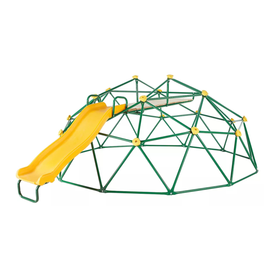
Adventure Dome
Style #: 164178
Please keep this instruction manual for future reference
For replacement parts, please call 1-866-370-2131 Monday – Friday 9:00 AM – 5:00 PM Eastern Time
General Customer Service: (888) 922-2336 7:00 am to 12:00 am CST (daily)
Live Chat at: www.academy.com
Email: customerservice@academy.com
Please keep this instruction manual for future reference
Advertisement

Related Manuals for AGame Adventure Dome


Summary of Contents for AGame Adventure Dome
- Page 1 Assembly Instructions and User Manual Adventure Dome Style #: 164178 Please keep this instruction manual for future reference For replacement parts, please call 1-866-370-2131 Monday – Friday 9:00 AM – 5:00 PM Eastern Time General Customer Service: (888) 922-2336 7:00 am to 12:00 am CST (daily) Live Chat at: www.academy.com...
- Page 2 Dear Valued Customer, Congratulations on your AGame Adventure Dome purchase! Please read and completely understand the contents of this owner’s manual. This manual contains specific instructions and warnings that must be followed to prevent injuries. This play set is for residential use only. This play set is NOT intended for public or commercial use. The warranty will be voided if the play set is used in a commercial application.
-
Page 3: Table Of Contents
Table of Contents Important Warnings and Instructions ..........4-6 Care and Maintenance Checklist ..........….. 7 Complete Product View..............…. 8 Tools ....................….. 9 Parts and Hardware List ............. 10-11 Assembly and Installation Instructions ........12-30 Warranty Information..............… 31 Note: Before beginning assembly of product, make sure all parts are present. -
Page 4: Important Warnings And Instructions
Important Warnings and Instructions WARNING READ ALL INSTRUCTIONS BEFORE ASSEMBLING OR USING THIS EQUIPMENT AGE LIMIT This product is designed to be used by up to three (3) children between the ages of 3 to 8. Maximum user weight is 100 pounds (45.4kg) each, with a combined maximum weight of 300 pounds (136kg). - Page 5 Important Warnings and Instructions Do not install your play set over hard surface, e.g. asphalt, concrete, packed earth, tile or brick floor. A fall onto a hard surface can result in serious injury or death to the user. The following is a list of recommended ground covers from the Consumer Product Safety Commission: SUGGESTED MATERIAL UNCOMPRESSED DEPTH...
- Page 6 Observing the following statements and warnings reduces the likelihood of serious or fatal injury. ALWAYS dress children appropriately for proper play, e.g. wear well-fitted rubber sole shoes, and remove loose or sharp items such as jewelry, hair accessories, or scarves that may become entangled in the equipment or cause injuries.
-
Page 7: Care And Maintenance Checklist
Care and Maintenance Checklist Complete Product View CARE & MAINTENANCE INSTRUCTIONS Inspect all nuts and bolts twice monthly during the usage season for tightness and tighten as required. It is particularly important that this procedure is followed at the beginning of each season. ... -
Page 8: Complete Product View
Complete Product View 8 / 31... -
Page 9: Tools
TOOLS NEEDED Wrench (Included) Big Allen Wrench (Included) Wrench (Included) Special Socket Wrench (Included) Medium Allen Wrench (Included) Tape Measure (Not Included) Hammer (Not included) Flat Head and Phillips Head Screwdriver (Not included) 9 / 31... -
Page 10: Parts And Hardware List
Parts List Part No. Description Picture Quantity Frame tube (27.75”) Frame tube (24.5”) Frame tube (30.98”) Frame tube (30.98”) With two holes Frame tube (28.54”) Frame tube (21.65”) Connect Tube Slide Platform Support Slide Platform Connect Tube Slide Top Support Bar Slide handle bar (Left) Slide handle bar (Right) Bracket... - Page 11 Hardware List Part No. Description Picture Quantity BOLT M8 X 1.57” BOLT M8 X 1.18” BOLT M8 X 0.98” BOLT M6 X 0.79 ” BOLT M6 X 1.38 ” BOLT M6 X 2.17 ” BOLT M6 X 2.56 ” BOLT M6 X 4.53 ” SCREW M8 WASHER (LARGE) M6 WASHER (SMALL)
-
Page 12: Assembly And Installation Instructions
Assembly Instructions STEP 1 Locate the following 30 pieces of #2 steel tubing parts and separate them into six groups of five. Connect 5 pcs of #2 steel tube together using #A, #J and #O as shown below. ... - Page 13 STEP 2 Connect two sets of previously assembled #2 tubes together with four pcs of #1 in the order shown below. Secure all tubes together with #A, #J, and #O as shown in the enlarged diagram. Repeat in the same manner to assemble three sets. Part# Hardware# 12 PCS...
- Page 14 STEP 3 Attach three pcs of #1 to the previously assembled tubes # 2 and #1. Secure using #C, #J, #M and #P in the order shown in the enlarged diagram. Repeat in the same manner to assemble three sets. Part# Hardware# 9PCS...
- Page 15 STEP 4 Connect the previously assembled tubes together with #1 to form the base of the dome. Secure with #C, #J, #M and #P as shown in the enlarged diagram. Part# Hardware# 9 PCS 6 PCS 12 PCS 6 PCS 6 PCS NOTE: Adjust the tubing to make sure the dome is evenly shaped as a circle.
- Page 16 STEP 5 Attach two pcs of #1 to # 2 and #1 using #B, #J, #M and #P as shown below. Part# Hardware# 2 PCS 1 PC 2 PCS 1 PC 1 PC 16 / 31...
- Page 17 STEP 6 Attach two pcs of #1 to # 2 and #1 using #A, #J and #O as shown below. Repeat in the same manner to connect the adjacent side. Part# Hardware# 4 PCS 2 PCS 4 PCS 2 PCS 17 / 31...
- Page 18 STEP 7 Connect tubes #3 (2pcs) and #6 to #1 and #2 in the order shown in the enlarged diagram. Repeat in the same manner for both sides as shown. Part# Hardware# 4 PCS 2 PCS 2 PCS 4 PCS 2 PCS 18 / 31...
- Page 19 STEP 8 Attach tubes #4 and #5 using #A, #J and #O as shown below. Part# Hardware# 1 PC 2 PCS 2 PCS 4 PCS 2 PCS 19 / 31...
- Page 20 STEP 9 Connect tubes #7 and #5 using #A, #J and #O as shown below. Part# Hardware# 1 PC 2 PCS 2 PCS 4 PCS 2 PCS 20 / 31...
- Page 21 STEP 10 Attach #13 to #5 and #6 using #A, #J and #O as shown below. Part# Hardware# 2 PC 2 PCS 4 PCS 2 PCS 21 / 31...
- Page 22 STEP 11 Attach #16 to #8 using #G, #L, #K, #N and #Q as shown in DIAGRAM A. Attach #9 to the outer sides of #8 using #G, #L, #K, #N and #Q as shown in DIAGRAM B. Part# Hardware# 2 PCS...
- Page 23 STEP 12 Connect #10 in between #11 and #12 and secure together with #8 using #E and #L. Part# Hardware# 1 PC 2 PCS 1 PC 2 PCS 1 PC 23 / 31...
- Page 24 STEP 13 Attach #8 to #4 using #E, #L, #N and #Q as shown below. Part# Hardware# 2 PCS 4 PCS 2 PCS 2 PCS 24 / 31...
- Page 25 STEP 14 Attach #9 to #13 using #D, #J, #M and #P as shown in DIAGRAM A. Attach #8 to #7 using # F, #L, #N and #Q as shown in DIAGRAM B. Hardware# Hardware# 2 PCS 2 PCS 4 PCS 4 PCS 2 PCS...
- Page 26 STEP 15 Insert X5-N into #17 and secure with #Z9, #Z6 and #Z4 as shown below. Part# Hardware# 1 PC 4 PCS X5-N 1 PC 4 PCS 4 PCS 4 PCS 4 PCS 26 / 31...
- Page 27 STEP 16 Lift the slide onto the platform and secure both sides to #11 and #12 using #H, #L, #K, #N and #Q as shown below Part# Hardware# 2 PCS 2 PCS 2 PCS 2 PCS 2 PCS 27 / 31...
- Page 28 STEP 17 Insert #15 groove side into #17 Slide bottom. Install in sequence #14 to #17 using #I as shown below. Part# Hardware# 11 PCS 48 PCS 1 PS Helpful Hint: It is recommended to use drill for easier assembly on this step. 28 / 31...
- Page 29 STEP 18 Attach #18 using #J, #P and #M to all tube connections shown below. Part# Hardware# 19 PCS 19 PCS 19 PCS 19 PCS Helpful Hint: Use the special socket wrench provided to fully tighten the bolts and nuts. 29 / 31...
- Page 30 STEP 19 – Anchor Secure the dome into the ground by hammering the 6 anchors #19 into the ground as shown below. Make sure the anchors are fully inserted into the ground to avoid any tripping hazards. Part# Hardware# Congratulations! You have now completed the product assembly.
-
Page 31: Warranty Information
Warranty Information This product has been manufactured under the highest standards of quality and workmanship. We warrant to the original consumer purchaser that all aspects of this product will be free of defects in material and workmanship for one year from the date of purchase.
Need help?
Do you have a question about the Adventure Dome and is the answer not in the manual?
Questions and answers