Table of Contents
Advertisement
Assembly Instructions &
User's Manual
Discovery 9 Metal Playset
Style #: 160393 Model #: MSC-4552
Please keep this instruction manual for future reference
For replacement parts please call 1-866-370-2131 Monday – Friday 9:00 AM – 5:00 PM Eastern Time
Customer Service: (888) 922-2336 7:00 am to 12:00 am CST (daily)
Live Chat at: www.academy.com
Email: customerservice@academy.com
1 / 39
Advertisement
Table of Contents

Subscribe to Our Youtube Channel
Related Manuals for AGame MSC-4552


Summary of Contents for AGame MSC-4552
- Page 1 Assembly Instructions & User’s Manual Discovery 9 Metal Playset Style #: 160393 Model #: MSC-4552 Please keep this instruction manual for future reference For replacement parts please call 1-866-370-2131 Monday – Friday 9:00 AM – 5:00 PM Eastern Time Customer Service: (888) 922-2336 7:00 am to 12:00 am CST (daily) Live Chat at: www.academy.com...
- Page 2 Dear Valued Customer, Congratulations on your Academy play set purchase! Please read and completely understand the contents of this owner’s manual. This manual contains specific instructions and warnings that must be followed to prevent injuries. This play set is for residential use only. This play set is NOT intended for public or commercial use. The warranty will be voided if the play set is used in a commercial application.
-
Page 3: Table Of Contents
Table of Contents Important Warnings and Instructions ..........4-6 Important Consumer Information Sheet ......... …7 Anchoring ..................8-9 Care and Maintenance Checklist ..........10-11 Complete Product View..............….12 Tools ....................…..13 Parts and Hardware List ............. 14-18 Assembly and Installation Instructions ........19-38 Warranty Information.............. -
Page 4: Important Warnings And Instructions
Important Warnings and Instructions WARNING READ ALL INSTRUCTIONS BEFORE ASSEMBLING OR USING THIS EQUIPMENT AGE LIMIT • This product is designed to be used by up to nine (9) children between the ages of 3 to 8. Maximum user weight is 100 pounds (45.4kg) each with a combined maximum weight of 900 pounds (409kg). - Page 5 Important Warnings and Instructions Do not install your play set over hard surface, e.g. asphalt, concrete, packed earth, tile or brick floor. A fall onto a hard surface can result in serious injury or death to the user. The following is a list of recommended ground covers from the Consumer Product Safety Commission: SUGGESTED MATERIAL UNCOMPRESSED DEPTH...
- Page 6 Important Warnings and Instructions Observing the following statements and warnings reduces the likelihood of serious or fatal injury. DO NOT allow children to twist the swing chains or ropes, or loop them over the top support bar as this may reduce the strength of the chain or rope.
-
Page 7: Important Consumer Information Sheet
Important Consumer Information Sheet The Consumer Product Safety Commission estimates there are more than 200,000 playground related injuries involving children each year. Injuries involving this hazard pattern tend to be among the most serious of all playground injuries and have the potential to be fatal, particularly when the injury is to the head. The surface under and around playground equipment can be a major factor in determining the injury-causing potential of a fall. -
Page 8: Anchoring
Anchoring (NOTE:ANCHORS ARE NOT INCLUDED-MUST BE PURCHASED SEPARATELY) There are different ways of anchoring the equipment, depending on the type of ground on which the equipment is to be installed. Make sure that all anchors are below ground level to prevent tripping. You should consult your local contractor to decide the most appropriate way to anchor the equipment in your location. - Page 9 Anchoring FRAME LEG 12-5/8” CONCRETE 5” 2” BRICK OR GRAVEL Note: The maximum fall height for this product is 6 feet. The minimum ground clearance between the bottom of the suspended plays and the playing or ground surface must be 8 inches. You must maintain a minimum of 8 inches of ground clearance.
-
Page 10: Care And Maintenance Checklist
Care and Maintenance Checklist AT THE BEGINNING OF EACH PLAY SEASON: • Tighten all hardware. • Lubricate all metallic moving parts per manufacturer’s instructions. • Check all protective coverings on bolts, pipes, edges, and corners. Replace if they are loose, cracked, or missing. •... - Page 11 Care and Maintenance Checklist CARE & MAINTENANCE INSTRUCTIONS •Inspect all nuts and bolts twice monthly during the usage season for tightness and tighten as required. It is particularly important that this procedure is followed at the beginning of each season. •Oil all metallic moving parts monthly during the usage period.
-
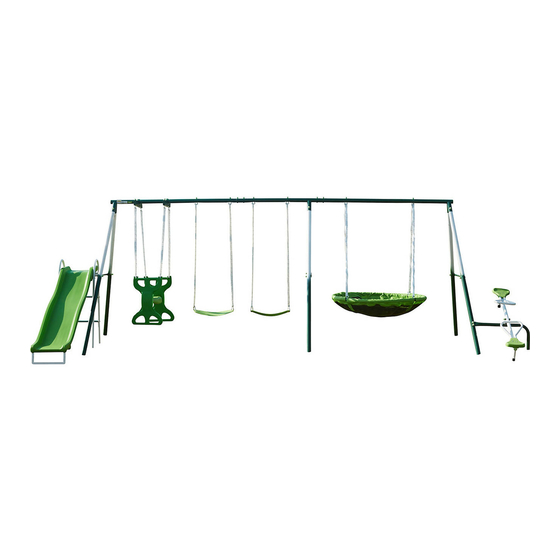
Page 12: Complete Product View
Complete Product View 12 / 39... -
Page 13: Tools
TOOL Wrench (Included) Big Allen Wrench (Included) Wrench (Included) Special Socket Wrench (Included) Medium Allen Wrench (Included) Tape Measure (Not Included) Hammer (Not included) Flat Head and Phillips Head Screwdriver (Not included) 13 / 39... -
Page 14: Parts And Hardware List
Parts List for Main Frame Part No. Picture Description Quantity RIGHT TOP BAR MIDDLE TOP BAR LEFT TOP BAR BOTTOM SECTION LEGR (FOR TEETER TOTTER) CROSS BAR (WITH TWO HOLES) CROSS BAR (WITH FOUR HOLES) END CAP (PRE-ASSEMBLED) Hardware – Swing Set Frame Part No. - Page 15 Part list for Roman Glider Part No. Picture Description Quantity LEG-GLIDE RIDER SEAT-GLIDE RIDER PVC COVERED CHAIN (PRE-ASSEMBLED) EYE BOLT WITH ATTACHMENT BOLT (PRE-ASSEMBLED) EYE BOLT (PRE-ASSEMBLED) Bracket for Roman Glider Part No. Picture Description Quantity BRACKET BRACKET CLAMP WASHER (5/16”) BOLT 5/16”...
- Page 16 Part list for Swing Seat Part No. Picture Description Quantity PVC COVERED CHAIN (PER- ASSEMBLED) EYE BOLT WITH ATTACHMENT BOLT (PRE-ASSEMBLED) SWING SEAT NYLON NUT 5/16" (8mm) PLASTIC CAP (CURVED FOR ARC WASHER) Part list for Flying Saucer Part No. Picture Description Quantity...
- Page 17 Parts used for Teeter Totter Part No. Picture Description Quantity SEAT SEAT SUPPORT HANDLE BAR U19-1 LEFT HANDLE BAR SUPPORT U19-2 RIGHT HANDLE BAR SUPPORT LSHAPED TUBE BOLT 5/16" x 3-2/9" (8mm x 82mm) BOLT 5/16" x 2-8/11" (8mm x 63mm) BOLT 5/16"...
- Page 18 Parts used for Slide Part No. Picture Description Quantity X1-N SLIDE SUPPORT (WITH OPENING) X2-N SLIDE SUPPORT X3-N SLIDE LEG TUBE X4-N SLIDE TOP SUPPORT BAR X5-N SLIDE FRONT SUPPORT SLIDE LADDER STEPS SLIDE Hardware used for Slide Part No. Picture Description Quantity...
-
Page 19: Assembly And Installation Instructions
Assembly Instructions AREA OF INSTALLATION - SWING SET TOP BAR STEP 1 – Assemble the top bar frame of the swing set Connect Top Bars A1, A2 and A3 together. Secure using B1, B5, B4 and B3 as shown below. Part# Hardware# 1 PC... - Page 20 AREA OF INSTALLATION - SWING SET TOP BAR Step 2 – Assemble Support Legs of Swing Set Frame Connect A4 and A5 to A1, A2 and A3. Secure all legs using B1, B5, B4 and B3 in the sequence shown in the enlarged diagram. Part# Hardware# 1 PC...
- Page 21 Assembly Instructions AREA OF IN STALLATION – CROSS BARS STEP 3 – Assemble Cross Bar to Support Legs Attach Cross Bar (# A6 and #A7) to the outer sides of Legs (# A5). Secure using B1, B6, B4 and B3 as shown in below.
- Page 22 Assembly Instructions AREA OF INSTALLATION – Roman Glider Step 4 - Assemble Roman Glider Place Seat-Glide (#L2) in the middle of both Leg-Glide (#L1). Secure using N9, N12 and N10 as shown below. Part# Hardware# 2 PCS 2 PCS 1 PC 4 PCS 2 PCS...
- Page 23 Assembly Instructions Step 5 – Connect Chain to Roman Glider Attach Roman Glider (#L1) to Chain (#J2). Secure using N8, N12 and N10, as shown below. Repeat the same process for all four chains. Part# Hardware# 2 PCS 4 PCS 8 PCS 4 PCS...
- Page 24 Assembly Instructions STEP 6 – Connect Chain to Frame Attach R8 and R3 to A1 Part# Hardware# 2 PCS 4 PCS 2 PCS 4 PCS 4 PCS 4 PCS Diagram A Attach J2 to R3 Part# Hardware# 2 PCS 4 PCS 2 PCS 4 PCS...
- Page 25 Assembly Instructions AREA OF INSTALLATION – SWING SEAT STEP 7 - Swing Seat Assembly Connect the swing seat to the chains by inserting J1 through K1 as shown in Diagram A. Connect swing set chains to the top bar by inserting J3 through A2. Secure with J8 and J6 as shown in Diagram B.
- Page 26 Assembly Instructions AREA OF INSTALLATION - FLYING SAUCER STEP 8 – Flying Saucer Assembly Slide Flying Saucer Tubes R4 into the pockets of Flying Saucer R7 as shown in DIAGRAM A. Connect the four tubes together and align the holes with the round holes facing downward. ...
- Page 27 Assembly Instructions Step 9 – Flying Saucer Assembly (continued) Insert Eye Bolt for Swing Chain R2A into the holes on A1 and secure with F2 and F1 as shown below. Part# Hardware# 2 PCS 2 PCS 27 / 39...
- Page 28 Assembly Instructions AREA OF INSTALLATION – TEETER TOTTER STEP 10 - Teeter Totter Assembly Attach U20 to A4. Align the holes on U20 to the two holes on the bottom of A4 and secure using U3, U4, U15 and U5 as shown below. Part# Hardware# 1 PC...
- Page 29 Assembly Instructions STEP 11 - Teeter Totter Assembly (continued) Attach U18 to U19-1 and U19-2 and secure using U9 and U21. Repeat the same process to install both sets. Part# Hardware# 2 PCS 4 PCS 19-1 2 PCS 4 PCS 19-2 2 PCS...
- Page 30 Assembly Instructions STEP 12 - Teeter Totter Assembly (continued) Secure U19-1 and U19-2 to U17 using U1, U4 and U5 as shown below. Repeat in the same manner for the other side Part# Hardware# 1 PC 4 PCS 8 PCS 4 PCS 30 / 39...
- Page 31 Assembly Instructions STEP 13 – Teeter Totter Assembly (continued) Secure U16 to U19-1 and U19-2 using U7, U8 and U6 as shown below. Part# Hardware# 2 PCS 4 PCS 4 PCS 4 PCS 31 / 39...
- Page 32 Assembly Instructions STEP 14 - Teeter Totter Assembly (continued) Secure U17 to U20 using U2, U14, U10 and U5 as shown below. Part# Hardware# 1 PC 1 PC 1 PC 1 PC 1 PC 32 / 39...
- Page 33 Assembly Instructions AREA OF INSTALLATION - SLIDE Step 15 - Slide assembly Insert Slide Front Support (X5-N) into Slide (Y2) and secure with Z9 and Z6. Part# Hardware# 1 PC 4 PC X5-N 1 PC 4 PC 33 / 39...
- Page 34 Assembly Instructions Step 16 - Slide assembly (continued) Insert Slide Leg Tube (X3-N) into X1-N and X2-N as shown below. Align the holes and hold in position. Connect the Slide Top Support Bar (X4-N) onto the Slide Supports (X1-N and X2-N) and secure both ends using Z1, Z6, Z3 and Z5 as shown below.
- Page 35 Assembly Instructions Step 17 - Slide assembly (continued) Connect Slide Ladder Steps (X6) to Slide Supports (X1-N and X2-N). Secure both sides using Z8, Z6 and Z6, Z4 as shown below. Part# Hardware# 2 PCS 4 PCS 8 PCS 4 PCS 35 / 39...
- Page 36 Assembly Instructions STEP 18 – Slide Assembly (continued) Lift the slide (Y2) and place it onto Slide Top Support Bar (X4-N). Secure Slide (Y2) to the leg tubes on both sides using Z2, Z6 and Z4 as shown below. ...
- Page 37 Assembly Instructions STEP 19 – Connect the slide to the swing set Connect the assembled slide to the swing set frame. Place Plastic Connector (Y1) between A7 and X1-N and secure together using Z7, Z6, Z3 and Z5 as shown below. Part# Hardware# 2 PCS...
- Page 38 Assembly Instructions Congratulations! You have now completed the swing set assembly. Please make sure to thoroughly check all parts and hardware to make sure all bolts and nuts are well secured before using the playground equipment. WARNING Do not let children use the playground equipment until it is properly assembled and anchored.
-
Page 39: Warranty Information
, service company , or consumer. We will not be responsible for labor charges and/or damage incurred in installation, repair or replacement nor for incidental or consequential damage. SP-6-MSC-4552-ADMY-19001 39 / 39...
Need help?
Do you have a question about the MSC-4552 and is the answer not in the manual?
Questions and answers