
Related Manuals for RuggedCom RuggedMAX WiN7013


Summary of Contents for RuggedCom RuggedMAX WiN7013
- Page 1 RuggedMAX™ WiN7000 High Power Base Station Installation Guide Revision 1.1 - November 3, 2011 www.ruggedcom.com...
- Page 2 ROX™, RuggedRated™, eRSTP™, RuggedBackbone™, and RuggedMAX™ are trademarks of RuggedCom Inc. RuggedRouter® is a registered trademark of RuggedCom Inc. Other designations in this manual might be trademarks whose use by third parties for their own purposes would infringe the rights of the owner.
-
Page 3: Table Of Contents
A. Connector and Cable Pinouts ..................... 36 A.1. Power and Ethernet Cable Pinouts ................36 A.2. Console Cable Pinouts ..................... 37 B. WiN7000 High Power Base Station Specifications .............. 38 C. List of Acronyms ......................... 41 D. Warranty ..........................42 RuggedCom® RuggedMAX™ Installation Guide Rev 1.1... - Page 4 4.3. WiN7000 High Power Base Station Web Interface: General Status page ......34 A.1. WiN7000 High Power Base Station Power Cable Pinout ..........36 A.2. 3-pin Console Connector Pinout ..................37 A.3. DB9F Console Connector Pinout ..................37 RuggedCom® RuggedMAX™ Installation Guide Rev 1.1...
- Page 5 3.5. -48 VDC Power System ....................32 A.1. WiN7000 High Power Base Station Power Cable Pinout ..........36 A.2. WiN7000 High Power Base Station Console Connector Pinout ........37 C.1. List of Acronyms ......................41 RuggedCom® RuggedMAX™ Installation Guide Rev 1.1...
-
Page 6: Fcc Statement And Cautions
RuggedCom® RuggedMAX™ Installation Guide Rev 1.1... -
Page 7: Introduction
The WiN7000 High Power Base Station can be equipped with copper or fibre network interfaces for flexible integration into the operator’s backbone. The WiN7000 High Power Base Station is supported by RuggedNMS™, RuggedCom’s comprehensive Network Management System. 1.1. About this Guide This installation guides describes the installation of the RuggedMAX™... -
Page 8: Capabilities And Features
• Quality of Service (QoS) management • Alarm management • Internal SNMP agent, enabling extensive In-Band (IB) management of the base station and its registered CPEs • R6 interface to ASN-GW profile C • Power requirement: 48VDC RuggedCom® RuggedMAX™ Installation Guide Rev 1.1... -
Page 9: Safety Information
See the figures below for two methods of power grounding (from the UL 60950-1 standard; according to UL 60950-22). When the unit is connected to a centralized DC Power System, the "+" side of the supply should be grounded, as per UL60950-1 and UL 60950-22 requirements. RuggedCom® RuggedMAX™ Installation Guide Rev 1.1... -
Page 10: Typical Centralized Dc Power System, Plant And Distribution Source-Grounded Dc
1. Introduction Figure 1.1. Typical Centralized DC Power System, Plant and Distribution Source-Grounded DC Power System Figure 1.2. Typical Centralized DC Power System, Plant and Distribution DC Power System Grounded at Equipment Location RuggedCom® RuggedMAX™ Installation Guide Rev 1.1... -
Page 11: Equipment Installation
Route all power supply cords so that people cannot walk on them or place objects on or against them. Walking on the cords or placing objects on or against the cords can damage the cords. RuggedCom® RuggedMAX™ Installation Guide Rev 1.1... -
Page 12: Servicing
• Falling when working at heights or with ladders • Injuries from dropping tools • Contact with AC wiring (power system connection) To reduce the risk of fire, use only 26AWG or larger telecommunication line cord. RuggedCom® RuggedMAX™ Installation Guide Rev 1.1... -
Page 13: Win7000 High Power Base Station Physical Specifications
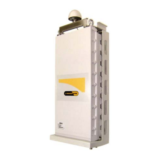
The assembled unit weighs approximately 15kg. For information on the WiN7000 High Power Base Station wiring connections, see Section 3.4.5, “Cable Connections”. Figure 1.3. WiN7000 Dimensions RuggedCom® RuggedMAX™ Installation Guide Rev 1.1... -
Page 14: Site And Installation Requirements
GPS antenna is mounted on top of the base station, only half of the sky will be visible to the antenna. This may not be enough for proper operation. RuggedCom® RuggedMAX™ Installation Guide Rev 1.1... -
Page 15: Installation Procedures
• 48V power supply for Copper and SFA configuration 3.3. Installation Tools • Phillips screwdriver • Wrench or socket set • Drill and 5/16" drill bit • Self-fusing electrical tape or insulating putty suitable for use in the unit’s installation environment RuggedCom® RuggedMAX™ Installation Guide Rev 1.1... -
Page 16: Installing The Base Station
5. Mount the power supply. 6. Mount the base station to the mounting bracket. 7. Connect all cables to the WiN7000 High Power Base Station and seal connections with suitable electrical tape or putty. RuggedCom® RuggedMAX™ Installation Guide Rev 1.1... -
Page 17: Win7000 High Power Base Station Mounting Bracket
3. Installation Procedures 3.4.1. WiN7000 High Power Base Station Mounting Bracket The mounting bracket is used for both pole- and wall-mount installations. Figure 3.1. Mounting Bracket RuggedCom® RuggedMAX™ Installation Guide Rev 1.1... -
Page 18: Pole Mounting
Assemble the fastening brackets to the mounting bracket using the 5/16" × 6" hex cap screws (Item 4), NF 16 hex nuts (Item 5), 5/16" flat washers (Item 6), and 5/16" spring washers (Item RuggedCom® RuggedMAX™ Installation Guide Rev 1.1... -
Page 19: Wall Mounting
Washer spring NC 1/4" Bolt NC 1/4" Screw 5/16" hex cap × 2" Washer flat 5/16" Washer spring 5/16" Dowel 5/16" Mounting upper bracket Table 3.2. WiN7000 High Power Base Station Wall Mount Parts List RuggedCom® RuggedMAX™ Installation Guide Rev 1.1... -
Page 20: Tower Mount
3.4.5. Cable Connections The WiN7000 High Power Base Station can be equipped with copper or fiber Ethernet connections. Figure 3.4. Fiber Optic Ethernet Port Option RuggedCom® RuggedMAX™ Installation Guide Rev 1.1... -
Page 21: Win7000 High Power Base Station Connectors And Cables
Optic SM Mini LC Optic 100M/1GMbit Network/Router/Switch Industrial Plug, ODVA Cable Connected to external ANT2 N type Female RG 6 or 9 antenna or omni-directional Antenna antenna Table 3.3. WiN7000 High Power Base Station Connectors and Cables RuggedCom® RuggedMAX™ Installation Guide Rev 1.1... -
Page 22: Ghz Band Cavity Filters Installation
Follow these steps to assemble the 2.3GHz cavity filters and connect them to the base station antennas. There are two types of cavity filters: one for A+B band, and one for C+D band. Figure 3.6. A+B Band Cavity Filter Figure 3.7. C+D Band Cavity Filter RuggedCom® RuggedMAX™ Installation Guide Rev 1.1... -
Page 23: A+B Band Cavity Filters Mounted On Baseplate
Position the cavity filters (Item 1 × 2) on the baseplate (Item 2). Secure the filters to the baseplate using Flat Washer (M5), Spring Washer (M5), and Hex Nut (M5) (Items 3, 4, and 5 × 8). Figure 3.8. A+B Band Cavity Filters Mounted on Baseplate RuggedCom® RuggedMAX™ Installation Guide Rev 1.1... -
Page 24: C+D Band Cavity Filters Mounted On Baseplate
Position the adaptor plate (MT-120018) on the baseplate in the position shown in Figure 3.10, “Adaptor Plate Mounted on Baseplate”. Secure the adaptor plate using Flat Washer (M5), Spring Washer (M5), and Hex Nut (M5) (Items 2, 3, and 4 × 4). RuggedCom® RuggedMAX™ Installation Guide Rev 1.1... -
Page 25: Adaptor Plate Mounted On Baseplate
Secure the adaptor bracket with Set Screw (M5) as shown in Figure 3.11, “Adaptor Bracket Mounted to Adaptor Plate”. Figure 3.11. Adaptor Bracket Mounted to Adaptor Plate Attach the wall mount bracket to the adaptor bracket. RuggedCom® RuggedMAX™ Installation Guide Rev 1.1... - Page 26 For pole mounting, attach the pole mounting bracket to the wall mounting bracket as shown Figure 3.13, “Pole Mount Bracket Assembly”. 10. Secure the pole mounting bracket with Flat Washer (M5), Spring Washer (M5), and Set Screw (M5) as shown in Figure 3.13, “Pole Mount Bracket Assembly”. RuggedCom® RuggedMAX™ Installation Guide Rev 1.1...
-
Page 27: A+B Band Cavity Filter Antenna Connections
11. Connect the RF cables to the cavity filters and the base station. Connect cavity filter IN to the base station. Connect cavity filter OUT to the antenna. Figure 3.14. A+B Band Cavity Filter Antenna Connections RuggedCom® RuggedMAX™ Installation Guide Rev 1.1... -
Page 28: C+D Band Cavity Filter Antenna Connections
3. Installation Procedures Figure 3.15. C+D Band Cavity Filter Antenna Connections RuggedCom® RuggedMAX™ Installation Guide Rev 1.1... -
Page 29: Weatherproofing
Begin to wrap the rubber-splicing or self-amalgamating tape. Start as close to the equipment body as possible. Stretch and wind the tape around the connector housing, ensuring there are no gaps in the tape. Figure 3.16. Wrapping the Connector with Rubber-splicing or Self-amalgamating Tape RuggedCom® RuggedMAX™ Installation Guide Rev 1.1... -
Page 30: Wrapping The Connector With Electrical Tape
Work mastic putty or duct sealing putty between the connector and the body of the radio or antenna. Ensure the putty fills any gaps not covered by the tape. Figure 3.19. Sealing Gaps with Putty RuggedCom® RuggedMAX™ Installation Guide Rev 1.1... -
Page 31: Power Connections
3.6. Power Connections 3.6.1. Copper and SFA Type Base Station The power system can be supplied by RuggedCom (WiNPS) or by the operator. Connect the power system DC + ETH output to the supplied connector and cable. Connect the other end (open end) of the supplied cable to the WiN7000 High Power Base Station DC + ETH connector. -
Page 32: Sfd Type Base Station
Connect +48V and GND Table 3.5. -48 VDC Power System Figure 3.21, “Positive 48V Configuration” Figure 3.22, “Negative 48V Configuration” show +48V and -48V configurations. Figure 3.21. Positive 48V Configuration Figure 3.22. Negative 48V Configuration RuggedCom® RuggedMAX™ Installation Guide Rev 1.1... -
Page 33: Setup
Area Connections Properties dialog appears with the General tab selected. Figure 4.1. Microsoft Windows Local Area Connection Properties dialog box In the Items list, select Internet Protocol (TCP/IP) and click the Properties button. The Internet Protocol (TCP/IP) Properties dialog appears. RuggedCom® RuggedMAX™ Installation Guide Rev 1.1... -
Page 34: Microsoft Windows Internet Protocol (Tcp/Ip) Properties Dialog Box
Launch your web browser and type http://192.168.100.100 in the address field. The Login window appears. Enter your user name and password and click Log In. The WiN7000 High Power Base Station web interface appears. Figure 4.3. WiN7000 High Power Base Station Web Interface: General Status page RuggedCom® RuggedMAX™ Installation Guide Rev 1.1... -
Page 35: Troubleshooting
1. Verify IP connectivity using a ping to the WiN7000 High Power Base Station unit IP address. 2. If there is no IP connectivity, verify the power connections. 3. If the power connections are okay and there is still no serial connection or IP connectivity, contact customer support. RuggedCom® RuggedMAX™ Installation Guide Rev 1.1... -
Page 36: Connector And Cable Pinouts
Figure A.1. WiN7000 High Power Base Station Power Cable Pinout Pin Number Type +TX Ethernet - TX Ethernet +RX Ethernet - RX Ethernet 48VDC (RTN) 48VDC (+) Ethernet GND Table A.1. WiN7000 High Power Base Station Power Cable Pinout RuggedCom® RuggedMAX™ Installation Guide Rev 1.1... -
Page 37: Console Cable Pinouts
• Cable type: 3 wire 28AWG • Cable connectors: proprietary 3 pin console connector; DBF9 • Cable length: 2m • The cable is supplied by RuggedCom. Figure A.3. DB9F Console Connector Pinout Figure A.2. 3-pin Console Connector Pinout 3-Pin Connector Pin Number... -
Page 38: Win7000 High Power Base Station Specifications
• Integrated or External Sector or Omni Antenna • Built-in GPS Network Interfaces: • 10/100BaseT Half/Full Duplex IEEE 802.3 CSMA/CD • ASN GW Compatibility WiMAX Forum R6, Profile C • Compatible with Cisco and WiChorus ASN-GW • Fiber Optic (Optional) RuggedCom® RuggedMAX™ Installation Guide Rev 1.1... - Page 39 • EN 55022 1613 & IEC61850-3 Safety: • 1613 section 5, 6.2 • IEC 60255-5 section 6.1.4 1613 & IEC61850-3 Environmental: • IEC61850-3 Section 5.2, 5.3, 5.5 • 1613 Section 10 • IEC 870-2-2 Section 3 RuggedCom® RuggedMAX™ Installation Guide Rev 1.1...
- Page 40 • EN 301 489-1 V1.8.1 CE Safety: • EN 60950-1 • IEC 60950-1 • EN 60950-22 CE Radio: • EN 302 326-2 FCC: • 47CFR Part15, Part27, Part90 Subpart B. • SRSP-301.7 Issue 2 (Industry Canada) RuggedCom® RuggedMAX™ Installation Guide Rev 1.1...
-
Page 41: List Of Acronyms
Local Area Network Line-of-sight MIMO Multiple-Input, Multiple-Output Network Management System NLOS Non-line-of-sight Radio Frequency WiMAX Worldwide Interoperability for Microwave Access RuggedMAX™ RuggedMAX WiMAX Product Family RuggedNMS™ RuggedMAX Network Management System Table C.1. List of Acronyms RuggedCom® RuggedMAX™ Installation Guide Rev 1.1... -
Page 42: Warranty
Appendix D. Warranty Appendix D. Warranty RuggedCom warrants this product for a period of five (5) years from the date of purchase. This product contains no user-serviceable parts. Attempted service by unauthorized personnel shall render all warranties null and void. For warranty details, visit www.RuggedCom.com...
Need help?
Do you have a question about the RuggedMAX WiN7013 and is the answer not in the manual?
Questions and answers