Advertisement
Quick Links
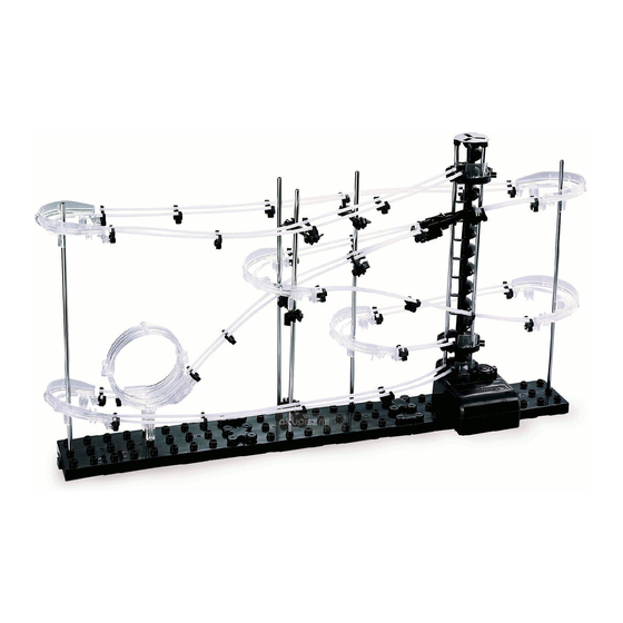
LEVEL 1
PRODUCT AND CONSUMER WARNING
CHOKING HAZARD: This product contains small parts and is not intended for children under 3.
• This product is intended for users 8 years of age and older.
• To avoid choking, keep small parts away from children.
• Use caution—this product contains parts with sharp edges.
• To avoid potential damage to the product, only insert the included marbles into the elevator.
Advertisement

Related Manuals for SpaceraiL LEVEL 1


Summary of Contents for SpaceraiL LEVEL 1
- Page 1 LEVEL 1 PRODUCT AND CONSUMER WARNING CHOKING HAZARD: This product contains small parts and is not intended for children under 3. • This product is intended for users 8 years of age and older. • To avoid choking, keep small parts away from children.
-
Page 2: Parts Included
PARTS INCLUDED Keep parts together to avoid misplacing them. ARM COMPONENTS Arm Clip Arm Sheath Arm Holder A Arm Holder B Arm Lock BASE COMPONENTS Base Base Holder A Base Holder B LOOPS, CORNERS, AND SPLIT COMPONENTS Corner A Corner B Rail Splitter Corner Stand Loop... - Page 3 PREPARE THE COASTER COMPONENTS ARMS (QTY: 5) Step 1: Attach one Arm Holder A and one Step 2: Insert Arm Lock through Step 3: Turn the Arm Lock Arm Holder B with one Arm Sheath. Insert Arm Holder A and Arm Clip. counter-clockwise to secure one Arm Clip into Arm Holder A.
-
Page 4: Base Assembly
BASE ASSEMBLY Step 2: Press Base Holder A and Base Holder B pieces into the Base blocks for a more secure hold. Step 1: Interlock Base block tabs as shown below. NOTE: Illustration of Shafts are 1:2.3 or (approximately 43%) of scale. SHAFT ASSEMBLY 261 mm 240 mm... -
Page 5: Elevator Assembly
ELEVATOR ASSEMBLY NOTE: Install the first Elevator Helix piece male side up and rotate it until it slides in place and engages with driver at the base of Power Box. Step 2: Connect Elevator Helix Step 3: Once the Corkscrew Step 1: Place a Shaft in the pieces together with the male part is built, attach three support... - Page 6 CUT THE RAIL TO SIZE 26mm Step 1: Measure each section and mark the cutting point with a pen. Step 2: Cut each section according to your measurement. Make sure to cut at a 90° angle. 73mm Tip: To help avoid do-overs and using too much Rail, cut generously (slightly longer than required) to begin with.
- Page 7 CONSTRUCTING THE ROLLERCOASTER INSTALL THE COASTER SHAFTS, LOOP AND ELEVATOR LOOP BACK FRONT LOOP STAND Step 1: Attach Loop Stand to the bottom of the Loop. Step 2: Attach Power Box to the Power Box Stand. LOOP PART SHAFT B SHAFT D PUSH SHAFT E...
- Page 8 ASSEMBLY TIPS & TRICKS Corner stability: To provide extra stability on the Rail and Corner connections: Cut the rail at a 45° angle Corners, place Corner Stands directly below the Corners. where it meets a Corner. This will help smooth out the transition as the Marble flies around the track.
- Page 9 CONNECT RAILS A, G, AND I Use the following illustrations and pictures as references for attaching the Rails to the structure: STEP 2 (G Rail) STEP 1 (A Rail) STEP 3 (I Rail) STEP 1 (A Rail) STEP 2 (G Rail) STEP 3 (I Rail) Step 1: Connect both A Rail sections between the Loop and the back bottom corner of Shaft A.
- Page 10 CONNECT RAILS J, B, AND H Use the following illustrations and pictures as references for attaching the Rails to the structure: STEP 4 (J Rail) STEP 6 (B Rail) STEP 5 (H Rail) STEP 4 (J Rail) STEP 5 (H Rail) STEP 6 (B Rail) Step 4: Connect both J Rail sections between the back top corner of Shaft A and the back top corner of Shaft E.
- Page 11 CONNECT RAILS D, E, F, AND C Use the following illustrations and pictures as references for attaching the Rails to the structure: STEP 8 (E Rail) STEP 7 (D Rail) STEP 9 (F Rail) STEP 10 (C Rail) STEP 8 STEP 7 (E Rail) (D Rail)
- Page 12 Seaich Corporation 1910 West 1040 South Salt Lake City, UT 84104 (833) 732-4242 orders@seaich.com Spacerails LLC www.spacerails.com...
Need help?
Do you have a question about the LEVEL 1 and is the answer not in the manual?
Questions and answers