
Subscribe to Our Youtube Channel
Related Manuals for REED ST-9918T

Summary of Contents for REED ST-9918T
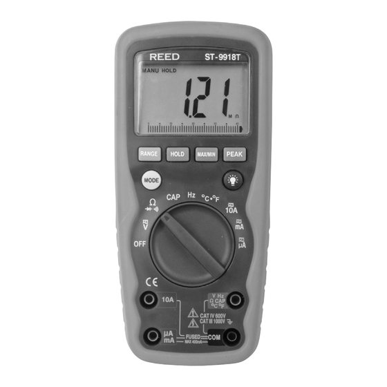
- Page 1 ST-9918T Model True RMS Autoranging Digital Multimeter Instruction Manual reedinstruments...
-
Page 2: Table Of Contents
AC Current Measurement ............7-8 Resistance (Ω) Measurement ............8 Continuity Check ................. 8 Diode Test ................... 9 Capacitance Measurement ............9 Frequency Measurement ............10 Temperature Measurement ............10 Specifications................10-14 Technical ................10-11 Accuracy ................12-14 Battery.&.Fuse.Replacement............15 For.service.on.this.or.any.other.REED.product,.contact.REED.Instruments. at.info@reedinstruments.com. reedinstruments... -
Page 3: Safety
Safety The.following.safety.information.must.be.observed.to.insure.maximum. personal.safety.during.the.operation.at.this.meter: •. Measurements.beyond.the.maximum.selected.range.must.not.be.at- tempted. •. Extreme.care.must.be.taken.when.measuring.above.50.V,.especially.on. live.bus-bars. •. To.measure.voltage,.the.instrument.must.not.be.switched.to.a.current.or. resistance.range,.or.to.the.diode.check.or.buzzer.position. •. Circuits.must.be.de-energized.and.isolated.before.carrying.out.resis- tance.tests. •. The.rotary.selector.switch.must.only.be.turned.after.removing.test.con- nections. •. All.external.voltages.must.be.disconnected.from.the.instrument.before. removing.the.battery. •. Test.leads.and.prods.must.be.in.good.order,.clean,.and.with.no.broken. or.cracked.insulation. •. UK.Safety.Authorities.recommend.the.use.of.fused.test.leads.when. measuring.voltage.on.high.energy.systems. •. Replacement.fuses.must.be.of.the.correct.type.and.rating. •. The.instrument.must.not.be.used.if.any.part.of.it.is.damaged. •. Warnings.and.precautions.must.be.read.and.understood.before.an. instrument.is.used..They.must.be.observed.during.the.operation.of.this. instrument. reedinstruments... -
Page 4: Display.symbol.descriptions
Safety Symbols: CauTion.refer.to.accompanying.notes..This.symbol.indicates. that.the.operator.must.refer.to.an.explanation.in.the.Operating. Instructions.to.avoid.personal.injury.or.damage.to.the.meter. CauTion risk.of.electric.shock..This.WaRninG.symbol.. indicates.a.potentially.hazardous.situation,.which.if.not.. avoided,.could.result.in.death.or.serious.injury. This.symbol.advises.the.user.that.the.terminal(s).so.marked.must. not.be.connected.to.a.circuit.point.at.which.the.voltage.with. respect.to.earth.ground.exceeds.(in.this.case).1000.VAC.or.VDC. Equipment.protected.throughout.. by.Double.Insulation.(Class.II) Equipment.complies.with.current.EU.directives. Display Symbol Descriptions . Continuity BaT. Low.Battery . Diode.test HoLD. Data.Hold auTo. AutoRanging aC. Alternating.Current.or.Voltage DC. Direct.Current.or.Voltage MaX/Min. Stores.the.highest.or.lowest.measurement PEaK Find.glitches.and.transients.without.a.scope . Backlight. V. Volts a, ma,ua . -
Page 5: Operating.instructions
operating instructions To.turn.on.the.instrument.turn.the.range.knob.from.the.OFF.position.to. any.measurement.range. •. For.the.best.battery.life.ALWAYS.turn.the.function.switch.to.the.OFF. position.when.the.meter.is.not.in.use..This.meter.has.Auto.OFF.that. automatically.shuts.the.meter.OFF.after.30.minutes.of.elapsed.time. •. On.some.low.AC.and.DC.voltage.ranges,.with.the.test.leads.not.con- nected.to.a.device,.the.display.may.show.a.random,.changing.reading.. This.is.normal.and.is.caused.by.the.high-input.sensitivity..The.reading.will. stabilize.and.give.a.proper.measurement.when.connected.to.a.circuit. MODE button To select AC or DC measurement when in Voltages, Amps, mA , uA ,Ω, ,°C.or.°F.ranges. HOLD button The.HoLD.function.allows.the.meter.to.“freeze”.a.measurement.for.later. reference. 1..Press.the.HoLD.button.to.“freeze”.the.reading.on.the.indicator... The.“HOLD”.message.will.be.appear.in.the.display. 2..Press.the.HoLD.button.again.to.return.to.normal.operation. BACKLIGHT button 1..Press.the.BaCKLiGHT.button.to.switch.on.the.display.light. 2..Press.BaCKLiGHT.button.again.to.exit.the.light.mode. - Page 6 Peak Hold button The.Peak.Hold.function.captures.the.peak.AC.or.DC.voltage.or.current.. The.meter.can.capture.negative.or.positive.peaks.as.fast.as.1.millisecond. in.duration.. 1..Turn.the.function.switch.to.the.A.or.V.position. 2..Use.the.MoDE.button.to.select.AC.or.DC. 3..Allow.time.for.the.display.to.stabilize. 4..Press.and.Hold.the.PEaK.button.until.“CAL”.appears.in.the.display.. This.procedure.will.zero.the.range.selected. 5..Press.the.PEaK.button,.Pmax.will.display. 6..The.display.will.update.each.time.a.higher.positive.peak.occurs. 7..Press.the.PEaK.button.again,.Pmin.will.display..The.display.will.now. update.and.indicate.the.lowest.negative.peak. 8..To.return.to.normal.operation,.press.and.hold.the.PEaK.button.until.. the.Pmin.or.Pmax.indicator.switches.off. noTE:.If.the.Function.switch.position.is.changed.after.a.calibration.the. Peak.Hold.calibration.must.be.repeated.for.the.new.function. selected. RANGE button When the meter is first turned on, it automatically goes into AutoRanging. This.automatically.selects.the.best.range.for.the.measurements.being. made.and.is.generally.the.best.mode.for.most.measurements... For.measurement.situations.requiring.that.a.range.be.manually.. selected,.perform.the.following: 1..Press.the.RanGE.button..The.“Auto.Range”.display.indicator.will.. turn.off,.The.“Manual.Range”.display.indicator.will.turn.on 2..Press.the.RanGE.button.to.step.through.the.available.ranges.until..
-
Page 7: Dc/Dc Voltage Measurement
DC/DC Voltage Measurement 1..Insert.the.black.test.lead.into.the.negative.COM.terminal.and.the.red. test.lead.into.the.positive.V.terminal. 2..Set.the.function.switch.to.the.VAC.or.VDC.position.. 3..Use.the.MODE.button.to.select.AC.or.DC.Voltage. 4..Connect.the.test.leads.in.parallel.to.the.circuit.under.test. 5..Read.the.voltage.measurement.on.the.LCD.display DC Current Measurement 1..Insert.the.black.test.lead.banana.plug.into.the.negative.(COM).jack. 2..For.current.measurements.up.to.4000uA.DC,.set.the.function.switch.to. the.uA.position.and.insert.the.red.test.lead.banana.plug.into.the.(uA).jack. 3..For.current.measurements.up.to.400mA.DC,.set.the.function.switch.to.the. mA.range.and.insert.the.red.test.lead.banana.plug.into.the.(mA).jack. 4..For.current.measurements.up.to.10A.DC,.set.the.function.switch.to.the. A.position.and.insert.the.red.test.lead.banana.plug.into.the.10A.jack. 5..Press.the.AC/DC.button.until.“DC”.appears.in.the.display. 6..Remove.power.from.the.circuit.under.test,.then.open.up.the.circuit.at. the.point.where.you.wish.to.measure.current. 7..Touch.the.black.test.probe.tip.to.the.negative.side.of.the.circuit..Touch. the.red.test.probe.tip.to.the.positive.side.of.the.circuit. 8..Apply.power.to.the.circuit. 9..Read.the.current.in.the.display..The.display.will.indicate.the.proper. decimal.point,.value.and.symbol. AC Current Measurement 1..Insert.the.black.test.lead.plug.into.the.negative.(COM).socket. 2..For.current.measurements.up.to.10A,.set.the.function.switch.to.the.A. position.and.insert.the.red.test.lead.plug.into.the.(10A).jack. 3..For.current.measurements.up.to.400mA,.set.the.function.switch.to.the. mA.range.and.insert.the.red.test.lead.banana.plug.into.the.(mA).jack. 4..For.current.measurements.up.to.10A.AC,.set.the.function.switch.to.the. A.position.and.insert.the.red.test.lead.banana.plug.into.the.10A.jack. continued ... reedinstruments... -
Page 8: Resistance (Ω) Measurement
5..Press.the.MODE.button..The.measurement.mode.will.change.between. AC.or.DC.as.required. 6..Remove.power.from.the.circuit.under.test,.then.open.up.the.circuit.at. the.point.where.you.wish.to.measure.current. 7..Touch.the.black.test.probe.tip.to.the.negative.side.of.the.circuit..And. touch.the.red.test.probe.tip.to.the.positive.side.of.the.circuit. 8..Apply.power.to.the.circuit. 9...Read.the.current.in.the.display..The.display.will.indicate.the.proper. decimal.point,.value.and.symbol. Resistance [ Ω ] Measurement WaRninG: To.avoid.electric.shock,.disconnect.power.to.the.unit.under.test. and.discharge.all.capacitors.before.taking.any.resistance.mea- surements..Remove.the.batteries.and.unplug.the.line.cords. Ω 1..Set.the.function.switch.to.the. .position. 2..Insert.the.black.test.lead.plug.into.the.negative.(COM).socket.and.the. Ω red.test.lead.plug.into.the.positive. .jack. Ω 3..Press.the.MODE.button.until.“ ”.appears.in.the.display. 4..Touch.the.test.probe.tips.across.the.circuit.or.part.under.test..It.is.best. to.disconnect.one.side.of.the.part.under.test.so.the.rest.of.the.circuit. will.not.interfere.with.the.resistance.reading. 5..Read.the.resistance.in.the.display..The.display.will.indicate.the.proper. decimal.point,.value.and.symbol. Continuity Check WaRninG:.To.avoid.electric.shock,.never.measure.continuity.on.circuits. or.wires.that.have.voltage.on.them. 1..Set.the.range.switch.to.the. .position. 2..Insert.the.black.lead.plug.into.the.COM.socket.and.the.red.test.lead. plug.into.the.positive. -
Page 9: Diode Test
Diode Test WaRninG:.To.avoid.electric.shock,.do.not.test.any.diode.that.has.. voltage.on.it. 1... S et.the.function.switch.to.the . . position. 2..Insert.the.black.test.lead.plug.into.the.COM.socket.and.the.red.test. lead.plug.into.the . . socket. 3..Press.the.MODE.button.until.“ ”.appears.in.the.display. 4..Touch.the.test.probe.tips.to.the.diode.or.semiconductor.junction.you. wish.to.test..Note.the.meter.reading. 5..Reverse.the.probe.polarity.by.switching.probe.position..Note.this.reading. 6..The.diode.or.junction.can.be.evaluated.as.follows: A..If.one.reading.shows.a.value.and.the.other.reading.shows.OL,.the. diode.is.good. B..If.both.readings.show.OL,.the.device.is.open. C..If.both.readings.are.very.small.or.zero,.the.device.is.shorted. noTE:.The.value.indicated.in.the.display.during.the.diode.check.is.the. forward.voltage. Capacitance Measurement WaRninG:.To.avoid.electric.shock,.discharge.the.capacitor.under.. test.before.measuring. 1..Set.the.function.switch.to.the.CaP.capacitance.position. 2..Insert.the.black.test.lead.banana.plug.into.the.negative.CoM.jack.and. the.red.test.lead.banana.plug.into.the.CaP.positive.jack. 3..Touch.the.test.probe.tips.across.the.part.under.test. 4..Read.the.capacitance.value.in.the.display. 5..The.display.will.indicate.the.proper.decimal.point.and.value. noTE:.For.very.large.values.of.capacitance.measurement.time.can.be. several minutes before the final reading stabilizes. The bar graph is.disabled.in.capacitance.measurement.mode..The.LCD.displays. -
Page 10: Frequency Measurement
Frequency Measurement 1... S et.the.function.switch.to.the.Hz.position. 2... I nsert.the.black.test.lead.banana.plug.into.the.negative.(COM).jack.and. the.red.test.lead.banana.plug.into.the.positive.Hz.jack. 3... T ouch.the.test.probe.tips.to.the.circuit.under.test. 4..Read.the.frequency.in.the.display..The.digital.reading.will.indicate.the. proper.decimal.point,.symbols.(kHz,.MHz).and.value. Temperature Measurement 1..Set.the.function.switch.to.the.Type.K.ºF.or.ºC.position. 2..Insert.the.Temperature.Probe.into.the.input.jacks,.making.sure.to.. observe.the.correct.polarity. 3..Press.the.MoDE.button.until.“ºF or ºC”.appears.in.the.display. 4..Touch.the.Temperature.Probe.head.to.the.part.whose.temperature.you. wish.to.measure..Keep.the.probe.touching.the.part.under.test.until.the. reading.stabilizes.(about.30.seconds). 5..Read.the.temperature.in.the.display. noTE: The temperature probe is fitted with a type K mini connector. . A.mini.connector.to.banana.connector.adaptor.is.supplied.for.. connection.to.the.input.banana.jacks. - Page 11 Maximun voltage between any terminal & earth ground:. 1000V.DC/AC.RMS Surge Protection:.. 8kV.peak.IEC.61010 aC TRuE RMS: The.term.stands.for.“Root-Mean-Square”.which.repre- sents.the.method.of.calculation.of.the.voltage.or.current.value..Average. responding.multimeters.are.calibrated.to.read.correctly.only.on.sine.waves. and.they.will.read.inaccurately.on.non-sine.wave.or.distorted.signals..True. rms.meters.read.accurately.on.either.type.of.signal. Display:. 4000.counts.LCD.display,.21mm.high Polarity:. Automatic,.(-).negative.polarity.indication. over-range:. “OL”.mark.indication. Low battery indication:.. The.“ ”.symbol.is.displayed.when.the.. battery.voltage.drops.below.the.operating.level Measurement rate: 2.times.per.second.nominal. auto power off:. Meter.automatically.shuts.down.after.approx.. . 30.minutes.of.inactivity.
-
Page 12: Accuracy
Accuracy Accuracy.is.given.at.18°C.to.28°C.(65°F.to.83°F),.less.than.70.%.RH DC Voltage.(Auto-ranging) Range Resolution accuracy 400.0mV 0.1mV +0.5%.of.rdg.+.2.digits 4.000V 40.00V 10mV 400.0V 100mV 1000V +0.8%.of.rdg.+.2.digits Input Impedance: 7.8MΩ. Maximum.Input:.1000V.dc.or.1000V.ac.rms. aC Voltage.(Auto-ranging) Range Resolution accuracy 400.0mV 0.1mV +0.8%of.rdg.+.3.digits 4.000V 40.00V 10mV 400.0V 100mV 1000V .+1.2%of.rdg.+.5.digits Input Impedance: 7.8MΩ. AC.Response:.50.Hz.60Hz Maximum.Input:.1000V.dc.or.1000V.ac.rms. - Page 13 aC Current.(Auto-ranging) Range Resolution accuracy 400.0uA 0.1uA +1.5%.of.rdg.+.5.digits 4000uA 40.00mA 10uA 400.0mA 100uA 10mA +3.0%.of.rdg.+.5.digits Overload.Protection:.0.5A./.1000V.and.10A./.1000V.Fuse. AC.Response:.50.Hz.to.60.Hz Maximum.Input:. 400uA.ac.rms.on.uA. 400mA.ac.rms.on.mA. 10A.ac.rms.on.10A.range. Resistance [Ω].(Auto-ranging) Range Resolution accuracy 400.0Ω 0.1Ω +0.8%.of.rdg.+.5.digits 4.000kΩ 1Ω +0.8%.of.rdg.+.2.digits 40.00kΩ 10Ω 400.0kΩ 100Ω 4.000MΩ 1kΩ +2.5%.of.rdg.+8digits 40.00MΩ 10kΩ...
- Page 14 Frequency.(Auto-ranging) Range Resolution accuracy 4.000kHz +1.2%.of.rdg.+.3.dgts 40.00kHz 10Hz 400.0kHz 100Hz 10.00MHz 1kHz +1.5%.of.rdg.+.4.dgts Sensitivity: >0.5V RMS while ≤1MHz Sensitivity:.>3V.RMS.while.>1MHz Input.Protection:.1000V.dc.or.1000V.ac.rms. Temperature Range Resolution accuracy -20°C~+760°C 1°C +3%.of.rdg.+5dgts -4°F~+1400°F 1°F +3%.of.rdg.+8dgts Sensor:.Type.K.Thermocouple Overload.protection:.1000V.dc.or.ac.rms.. Diode Test Test current Resolution accuracy 1Ma.typical/. 1.mV +10%.of.rdg.+.5.digits Open.MAX.3V Open.circuit.voltage:.MAX..3V.dc.
-
Page 15: Battery.&.Fuse.replacement
Battery & Fuse Replacement WaRninG:.To.avoid.electric.shock,.disconnect.the.test.leads.from.any. source.of.voltage.before.removing.the.battery.or.fuse.cover.. Do.not.operate.your.meter.with.the.cover.removed..Be.sure. it.is.in.place.and.fastened.securely. Battery Replacement When.the.battery.level.gets.low.or.falls.below.the.operating.voltage,.the. battery.warning.symbol.“ ”.will.appear.in.the.LCD.display. 1..Disconnect.the.test.leads.from.the.meter. 2..Open.the.battery.cover.by.loosening.the.screw.using.a.Phillips.head. screwdriver. 3..Insert.the.battery.into.battery.holder,.observing.the.correct.polarity. 4..Put.the.battery.cover.back.in.place..Secure.with.the.two.screws. noTE: If.your.meter.does.not.work.properly,.check.the.fuses.and.battery. to.make.sure.that.they.are.still.good.and.that.they.are.properly. inserted. Replacing The Fuses 1..Disconnect.the.test.leads.from.the.meter.and.any.item.under.test. 2..Open.the.fuse.door.by.loosening.the.screw.on.the.door.using.a.Phillips. head.screwdriver. 3..Remove.the.old.fuse.from.its.holder.by.gently.pulling.it.out.. 4..Install.the.new.fuse.into.the.holder. 5..Always.use.a.fuse.of.the.proper.size.and.value.(0.5A/1000V.fast.blow. for.the.400mA.range,.10A/1000V.fast.blow.for.the.10A.range). 6..Put.the.fuse.door.back.in.place..Insert.the.screw.and.tighten.it.securely. For.service.on.this.or.any.other.REED.product,.contact.REED.Instruments. at.info@reedinstruments.com. reedinstruments... - Page 16 notes _________________________________________ ________________________________________________ ________________________________________________ ________________________________________________ ________________________________________________ ________________________________________________ ________________________________________________ ________________________________________________ ________________________________________________ ________________________________________________ ________________________________________________ ________________________________________________ ________________________________________________ ________________________________________________ ________________________________________________ ________________________________________________ ________________________________________________ ________________________________________________ reedinstruments...
Need help?
Do you have a question about the ST-9918T and is the answer not in the manual?
Questions and answers