Table of Contents
Advertisement
Advertisement
Table of Contents

Subscribe to Our Youtube Channel
Related Manuals for AEM 30-5501


Summary of Contents for AEM 30-5501
- Page 1 CD-7/CD-7L COLOR DASH DISPLAY CAN LOGGER SYSTEM 30-5500 30-5501 30-5502 30-5503 AEM Performance Electronics 2205 126th Street Unit A, Hawthorne, CA 90250 Phone: (310) 484-2322 Fax: (310) 484-0152 http://www.aemelectronics.com Instruction Part Number: 10-5500 Document Build 11/17/2016...
- Page 2 Part I - Quick Start Guide The manual contains two parts. Part I is a quick start guide that includes basic information to get you up and running quickly.
-
Page 3: Kit Contents
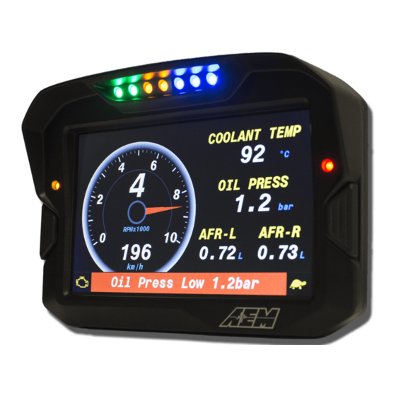
Introducing AEM DashDesign The AEM Color Dash Display and CAN Logger includes the AEM CD-7 / CD-7L color display and AEM DashDesign editing software. Screen pages are designed graphically. The screen layout displayed in AEM DashDesign is identical to the layout displayed on the AEM CD-7 / CD-7L. - Page 4 CD-7 Features · Full color CAN display and logger (CD-7L only) · Completely user definable CAN receive · Dual CAN bus · Full graphics display with up to 6 different pages · Unit ships with 6 display pages for the AEMNet data stream as the default setup ·...
- Page 5 CD-7 Mechanical and Mounting...
- Page 6 CD-7 Harness and Wiring...
-
Page 7: Installing Usb Drivers
· Click the Next button and the driver installation will proceed automatically. VDM for GPS speed and lap timing The AEM Vehicle Dynamics Module, PN 30-2203 can be used in conjunction with the AEM CD-7L dash for lap timing and track mapping features. - Page 8 · Continuous time data can be used for Infinity USB log file naming · Accelerometers supply all 3-axis acceleration data for chassis tuning · Ideal for road racers who want to use the gyrometer data for suspension adjustments · Perfect for drag racers who want G-loads and wheel stand data ·...
-
Page 9: Installation
Installation The VDM is equipped with an AEMnet connector (power, ground, and CAN) so that it is a true plug and play experience when used with other AEMnet products such as the Infinity ECU. Ideally, the VDM module should be installed near the center (both fore/aft and side-to-side) of the vehicle and as low as possible. -
Page 10: Status Led
GREEN 4 or greater satellites in view OTHER Please contact AEM Support Channels / Data The VDM utilizes an internal 5Hz GPS/GLONASS receiver with a matching external active antenna. Faster time to fix, and better global coverage is afforded by the support of both the GPS and GLONASS constellations. -
Page 11: Display Setups
Default Display Setups AEM supplied setup files will be located in the \Documents\AEM\DashDesign\Setups folder. You can copy entire pages from another file. First, make sure the target page is open and selected and that the layout is unlocked. - Page 12 Select the screen you want to import by clicking on the screen name and Clicking OK. NOTE: Any missing bitmaps and bitmap selectors will be imported with the page. Bitmaps of the same name are not replaced which potentially could cause unexpected results if bitmaps had been changed between setups.
- Page 13 Save button. To save a setup with the current name, select File | Save. If a setup or AEM DashDesign is closed and the setup has changed since the last save, a prompt will appear asking if the changes to the setup are to be saved. Select Yes to save the changes, No to abandon the changes or Cancel to return to editing the current setup.
- Page 14 The Layout Locked feature displayed at the bottom right of the screen prevents unwanted moving of screen items. The Layout Locked feature can be disabled by going to File | Lock Layout or by clicking the red Layout Locked area of the screen. Caution as inadvertent clicks and drags can move items unintentionally. Some basic editing of the default screens is possible even with the Layout Locked feature turned on.
- Page 15 highlight the text and edit. Double clicking on the "0" in the example above opens the value label editor. This is live data displayed on the screen. Here you can change the input displayed at this location. Click on the drop down to view a list of available channels.
- Page 16 You can think of the display editor as a collection of tools for creating items on your screens. A AEM DashDesign setup consists of four logical components: Sources, outputs, sensors and gauges. These are defined as follows: · Sources or primary inputs are raw data manipulated by an operation.
- Page 17 Default CAN .dbc Support The AEM DashDesign includes a CAN .dbc import feature. A .dbc file is a standardized format for defining a set of CAN messages. Click on the CAN Receive tab in the Setup Editor. Click on the Import DBC... button to load or append a new .dbc file.
- Page 18 Available .dbc files will be located in the \Documents\AEM\DashDesign\DBC folder. Selecting a file will open the import dialog. The levels can be expanded by clicking on the plus symbol.
- Page 19 Bit string operations. The channels are now available for assignment. Logging (CD-7L only) AEM CD-7 / CD-7L has 200Mbytes of internal data logging memory and supports logging rates of up to 100Hz. Data is downloaded and analyzed with AEMData Analysis software.
- Page 20 To download log files from an AEM CD-7L, connect the USB cable between the dash and your PC. Launch AEMData analysis software and turn on the switched ignition power to the Dash. The message below will be displayed when AEMData detects a connection to the dash.
- Page 21 AEM DashDesign communicates with the AEM CD-7 / CD-7L via USB. To upload a setup: · Open a display setup. · Connect the AEM CD-7 / CD-7L to the PC using a USB cable. The AEM CD-7 / CD-7L will go into upload mode and will show "USB cable connected"...
- Page 22 · Select Setup | Display | CAN Receive Updating Color Display Firmware As part of the continuing development process, from time to time new versions of the AEM CD-7 / CD-7L firmware will be released with new DashDesign installers. To upload the new firmware: ·...
- Page 23 Part II - Advanced Setup Part II contains more advanced setup information.
-
Page 24: The Setup Editor
The Setup Editor The AEM DashDesign Setup Editor is used to configure the non-visual objects of a setup i.e. Outputs and Operations. Some outputs use more than one input depending on the operation used. The setup editor is accessed by selecting Setup | Display.. - Page 25 CoolantTemp F = (CoolantTemp*1.8) + 32 This is a simple unit conversion for converting degrees C to degrees F. The next example uses EngineProtectionState_raw as the Primary Input. This input has two possible values with are 0 or 1. A Bit String operation is used to convert these values into text strings that can be displayed on the dash.
- Page 26 The “Start Bit” refers to the location of the LSB. The message contents and the byte/bit numbering can be viewed by clicking on the … button for each message.
- Page 27 Scalars Operation The scalar sensor applies a gain (if specified) to the input which is then multiplied by the scalar and the offset added. If signed is ticked and the gain is not set to NONE, the input is treated as a twos compliment number. The scalar sensor is used for linear signals.
-
Page 28: Functions Operation
Functions Operation The function table sensor is used when a non-linear signal needs to be processed. The function table sensor applies a gain (if specified) to the input and looks up the input in the function table to produce the appropriate output. - Page 29 The Time Filter parameters have the following meanings: · Update period: Specifies the rate at which values are sent to outputs and gauges used by this output. For example, if the Update Period is set at 1000, a gauge displaying the value from this output will update once per second.
- Page 30 To create a bit string operation, add a name for the operation in the Bit String tab and click on the (...) button to show the bit string editor: The priority determines the order in which the bitmasks are evaluated with low numbers being a higher priority. This ensures that if two bitmasks match, only the highest priority output string is returned from the sensor.
-
Page 31: Alarm Operation
The bitmap selection count is the number of bitmaps used in the sensor and is at least two. The first bitmap is shown by default. Subsequent bitmaps are shown according to the settings in the Bitmap Selections box. · Index - The number of the selection bitmap for which the following settings are made. For example, if the selection count is set to 3, 1 will specify the first selectable bitmap and 2 will specify the second selectable bitmap. - Page 32 Select an Input from the drop down list along with Condition and Limit selections. In the example above, the Input AFR1_Gas is checked against a maximum condition of 15:1 AFR. Click the Add button to add additional criteria. Above, the input EngineSpeed is added as an "AND" condition with a limit of 0 RPM. With this logic, IF AFR1_Gas is greater than 15 AND EngineSpeed is greater than 0 (engine running), the alarm will trigger.
- Page 33 The Retrigger value specifies a timeout in seconds after which the alarm (if still triggered) will toggle to untriggered and back to triggered. This is useful for when an alarm has been used to trigger a page change, usually showing a warning to the driver, for example, low oil pressure. The driver can select the standard page again to cancel the alarm.
- Page 34 (it is set to zero when the unit is built). To set up the odometer, choose Setup | Odometer. Select an output that is road speed km per second. AEM DashDesign will automatically create an output called ODOMETER which is scaled in km and can be displayed on the screen.
- Page 35 The following channels are used for lap timing and track mapping. Most AEM default setups include a lap timing screen. The VDM for GPS speed and lap timing section describes the basic setup and configuration of a GPS input for speed and position. Once configured, the screen will update with current data as the laps progress.
- Page 36 Go to Setup | Lap Timing... Select the GPS button to configure for GPS lap timing. A virtual start/finish line creation feature allows you to use the beacon input (violet wire in flying lead harness) to set a virtual start/finish line.
- Page 37 More details on Track Editing can be found in the AEMData documentation. CD-7 & CD-7L Settings...
- Page 38 Default is empty and controlled by the flying lead harness input. Shift Lights & LEDs The LED and shift light setup will be pre-configured with AEM supplied setup files. The Alarm outputs used to trigger the LEDs can be adjusted in the Setup Editor as shown in the example below.
-
Page 39: Alarm Page
Alarm Page AEM setups will come pre-configured with many optional Alarm outputs. Choose the ones you want to trigger the Alarm Page. On Change Page The On Change Page allows you to setup a custom page that will be displayed when any changes are detected on selected channels. -
Page 40: Display Screens
70% gives almost as much brightness without overdriving the backlight. 5%-10% is appropriate for night mode. Display Screens The AEM CD-7 / CD-7L supports 6 screen pages. The display also has a monitor list which enables permanent monitoring of data and a splash screen that appears when the display starts. Display Scaling By default, AEM DashDesign displays the screens at actual screen size (100%). - Page 41 However, it is possible to show the editor windows at different scalings by selecting and appropriate value from the Display | Display Scale menu. Supported scales are 75%, 100% (default), 125%, 150%, 175% and 200% The Monitor Screen Normally a given output is only monitored if used by a gauge on the currently displayed screen. In certain circumstances however, it is necessary to monitor some outputs irrespective of whether or not they are used by the currently displayed screen page.
- Page 42 · Gauge Background – Default background color of a gauge. · Gauge Line – Default line color of a gauge used in drawing the outline. · Gauge Fill – Default fill color of a gauge used in bars. · Gauge Text – Default text color of a gauge. Adding a Gauge Once a screen page is open, it is possible to add gauges to the screen.
-
Page 43: Using Copy And Paste
· Move the cursor to the border of the gauge which requires resizing. The pointing hand cursor changes to a sizing cursor depending on the position: · If the cursor is at the top left or bottom right corner of the gauge the cursor changes to a NW-SE cursor and is resized by dragging that corner. - Page 44 The standard gauge properties are as follows: · Name - The name is used to identify the gauge in the Edit menu. AEM DashDesign assigns a name to a new gauge automatically although it is useful to give gauges more meaningful names as it makes them easier to identify in the Edit menu.
- Page 45 Character Description Notes X or x Display in hexadecimal Must be first character in format B or b Display in binary Must be first character in format Force leading sign character e.g. +5.3 is displayed instead of 5.3 Indicates an optional digit e.g.
- Page 46 Tacho Gauges The tacho gauges are typically used with engine speed or road speed and are available as either a curved bar gauge or a round gauge. They use minimum, maximum and graticule size in the same manner as bars but also have labeled graticules, the frequency of which is specified by the label frequency property.
- Page 47 It can be seen that with these options, the tacho can effectively be divided into three separate different colored regions. Text Label Gauge The Text Label gauge is a static gauge (it has no input) that is used to label other gauges and provide static information to the user.
- Page 48 Variable String Gauge The variable string gauge is used to display text from a string output such as a bit string output. The Justification property specifies whether the text is aligned to the left, right or centre of the bounding rectangle. Note: It is important to select the background color of the value gauge to be the same as the color of the background the gauge is over.
- Page 49 Value Gauge The Value Gauge shows the value of the output specified in the Input property according to the format specified in the Format property. The Justification property specifies whether the text is aligned to the left, right or centre of the bounding rectangle. Note: It is important to select the background color of the value gauge to be the same as the color of the background the gauge is over.
- Page 50 Progressive Limit Gauge The Progressive Limit gauge is typically used to signal an approaching rev limit by means of several boxes that change color as the rev limit approaches. This gauge has the following special properties: · Box Count is the number of boxes in the gauge. ·...
- Page 51 Bitmap Gauge The Bitmap gauge is used to show a bitmap from a file or the output of a bitmap selector output. The Bitmap property has a drop down box from which any bitmap selector outputs and bitmaps currently present in the setup is selected.
- Page 52 · Black 0x0000 (0) · White 0xFFFF (65535) · Red 0xF800 (63488) · Green 0x07E0 (2016) · Blue 0x001F (31) · Cyan 0x07FF (2047) · Yellow 0xFFE0 (65504) Typically, a function table will be used to map a given value to a specific color. To avoid interpolation between the color values, the function table should be set up such that a range of values defines one color.
- Page 53 Cross Hair Gauge The Cross Hair gauge uses two inputs to move a cross hair around a box. The cross hair gauge has the following special properties: · XInput, YInput specify the inputs for the X and Y axes of the gauge. ·...
- Page 54 · Input - The output for which the line is drawn. · Line color - The color of the line. · Minimum - Specifies the lower range of the y axis of the graph for this line. If the value of the output for this line falls below this value, the line will be drawn at the minimum value.
-
Page 55: 12 Month Limited Warranty
AEM’s option, w hen determined by AEM that the product failed due to defects in material or w orkmanship. This w arranty is limited to the repair or replacement of the AEM part. In no event shall this w arranty exceed the original purchase price of the AEM part nor shall AEM be responsible for special, incidental or consequential damages or cost incurred due to the failure of this product. - Page 56 Default colors - H - Default setups Deleting gauges Display editor Historical graph gauge Display screens - I - - E - Installation ECU string Installing AEM DashDesign Editing gauge properties Installing USB Drivers Introduction - F - Features...
- Page 57 Index Sensor - L - scalar Settings Setup Lap timing 7, 35 editor LEDs Setup editor Limit filter Setups 11, 12 Logging creating opening - M - saving uploading Monitor screen Shape gauge Mounting Shift lights Moving gauges Spash screen Standard gauge properties - O - - T -...
Need help?
Do you have a question about the 30-5501 and is the answer not in the manual?
Questions and answers