AEM CD-7 User Manual
Can display dash & logger system
Hide thumbs
Also See for CD-7:
- Quick start manual (15 pages) ,
- Quick start manual (15 pages) ,
- User instructions (2 pages)
Table of Contents

Subscribe to Our Youtube Channel
Related Manuals for AEM CD-7


Summary of Contents for AEM CD-7
-
Page 1: User Manual
CAN DISPLAY DASH & LOGGER SYSTEM USER MANUAL AEM Performance Electronics 2205 126th Street Unit A, Hawthorne, CA 90250 Phone: (310) 484-2322 Fax: (310) 484-0152 http://www.aemelectronics.com Instruction Part Number: 10-5500-B Document Build 3/28/2018... -
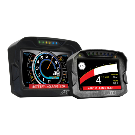
Page 2: Introducing The Aem Can Dash
Introducing The AEM CAN Dash The AEM Color Dash Display and CAN Logger includes the AEM Dash color display and AEM DashDesign editing software. Screen pages are designed graphically. The screen layout displayed in AEM DashDesign is identical to the layout displayed on the AEM Dash. - Page 3 1 x USB communication cable · 1 x USB bulkhead extension cable · documentation 30-5502 Contents: · 1 x CD-7 · 4 x AV Mount Hardware (attached to dash) · 1 x I/O harness · 1 x power harness ·...
- Page 4 30-5503 Contents: · 1 x CD-7L · 4 x AV Mount Hardware (attached to dash) · 1 x I/O harness · 1 x power harness · 1 x USB communication cable · 1 x USB bulkhead extension cable · 1 x Vehicle Dynamics Module ·...
- Page 5 30-5601 Contents: · 1 x CD-5L · 4 x AV Mount Hardware (attached to dash) · 1 x I/O harness · 1 x power harness · 1 x USB communication cable · 1 x USB bulkhead extension cable · documentation 30-5602 Contents: ·...
-
Page 6: Dash Features
30-5603 Contents: · 1 x CD-5GL · 4 x AV Mount Hardware (attached to dash) · 1 x I/O harness · 1 x power harness · 1 x USB communication cable · 1 x USB bulkhead extension cable · 1 x GPS Antenna ·... -
Page 7: Dash Mechanical And Mounting
Dash Mechanical and Mounting CD-7 Mechanical... - Page 8 CD-5 Mechanical...
-
Page 9: Dash Harness And Basic Wiring
Dash Harness and Basic Wiring... -
Page 10: Optional Obdii And Power Cable Kits
Optional OBDII and Power Cable Kits... -
Page 11: Installing Aem Dashdesign
· Click the Next button and the driver installation will proceed automatically. VDM to Dash The AEM Vehicle Dynamics Module, PN 30-2206 can be used in conjunction with the AEM dash for lap timing and track mapping features. VDM Features: ·... -
Page 12: Installation
· Status LED indicates power & GPS signal · Weather resistant enclosure with IP67 rated GPS/GLONASS antenna Go to Setup | Lap Timing... Select the GPS button to configure for GPS lap timing. A virtual start/finish line creation feature allows you to use the beacon input (violet wire in flying lead harness) to set a virtual start/finish line. -
Page 13: Status Led
GREEN 4 or greater satellites in view OTHER Please contact AEM Support Channels / Data The VDM utilizes an internal 10Hz GPS/GLONASS receiver with a matching external active antenna. Faster time to fix, and better global coverage is afforded by the support of both the GPS and GLONASS constellations. -
Page 14: Air/Fuel Sensors And Devices To Dash
GPS Course [deg] Course over ground, NOT heading GPS Satellite Count "Visible" number of satellites GPS Valid 1 = Valid Fix, 0 = No Fix GPS Year UTC Time GPS Month UTC Time GPS Day UTC Time GPS Hours UTC Time GPS Minutes UTC Time GPS Seconds... -
Page 15: Channel Calibration
Vehicle setups include carburated or fuel injected, drag race or road race, with or without AEM VDM and US or SI units. All layouts are based on the suggested channel assignments listed in the pinout in the CAN Sensor Module instructions. -
Page 16: Obdii Setups
Assign the closed throttle voltage to 0 and the full open throttle voltage to 100. OBDII Setups AEM’s dash with optional OBDII interface cable P/N 30-2217 puts multiple channels of data at your fingertips by reading the CAN bus stream of your 2008+ model year vehicle’s OBD port and transmitting those channels to the dash. - Page 17 Connect the OBDII connector to your vehicle's OBDII port then unplug the USB cable to begin the scan.
- Page 18 The dash will scan your vehicle and identify all available PIDs. When the scan is complete the message Reconnect USB cable to complete process will be displayed on the dash. The following window will be displayed in the Dash Design software. At this point in the process, you have the option to press the right button on the dash to scroll through a live display of available PID data.
- Page 19 Open the Setup Editor. OBDII PIDs will be automatically added to your list of available outputs. The circled examples above represent the same PID from different vehicle ECUs. In these cases, the system will append a suffix E2 for ECU2 and so on but can be ignored as they are non standard PIDs and may perform differently from expected.
-
Page 20: Editing Display Setups
This is a complete listing of available PIDs. An AEM supplied setup file for OBDII messages will be located in the \Documents\AEM\DashDesign\Setups\Generic folder. The basic default OBDII file is named Default-Black- OBD2.aemcd7. Complete PID list will vary between cars so modification to the default setup is encouraged to view desirable data. -
Page 21: Creating A New Display Setup
If a setup or AEM DashDesign is closed and the setup has changed since the last save, a prompt will appear asking if the changes to the setup are to be saved. Select Yes to save the changes, No to abandon the changes or Cancel to return to editing the current setup. -
Page 22: Basic Editing Of Default Setups
Select the screen you want to import by clicking on the screen name and Clicking OK. Basic Editing of Default Setups To view screens for editing go to Display | Screen X... - Page 23 The Layout Locked feature displayed at the bottom right of the screen prevents unwanted moving of screen items.
- Page 24 The Layout Locked feature can be disabled by going to File | Lock Layout or by clicking the red Layout Locked area of the screen. Caution as inadvertent clicks and drags can move items unintentionally. Some basic editing of the default screens is possible even with the Layout Locked feature turned on. It is a good idea to leave the Layout Locked activated until you specifically need to move or delete a gauge.
-
Page 25: Uploading A Setup To A Display
· Open a display setup. · Connect the AEM Dash to the PC using a USB cable. The AEM Dash will go into upload mode and will show "USB cable connected" · Select File | Upload to display... or press Ctrl + U ·... -
Page 26: The Display Editor
The display editor is the core tool for editing a setup. To open the tool, go to Setup | Display... You can think of the display editor as a collection of tools for creating items on your screens. An AEM DashDesign setup consists of four logical components: Sources, outputs, sensors and gauges. -
Page 27: Default Can .Dbc Support
Default CAN .dbc Support The AEM DashDesign includes a CAN .dbc import feature. A .dbc file is a standardized format for defining a set of CAN messages. Click on the CAN Receive tab in the Setup Editor. Click on the Import DBC... button to load or append a new .dbc file. - Page 28 Available .dbc files will be located in the \Documents\AEM\DashDesign\DBC folder. Selecting a file will open the import dialog. The levels can be expanded by clicking on the plus symbol.
-
Page 29: Log Start/Stop Conditions
Bit text operations. The channels are now available for assignment. Logging AEM Dash has 200Mbytes of internal data logging memory and supports logging rates of up to 1000Hz. Data is downloaded and analyzed with AEMData Analysis software. To configure logging, select Setup | Logging to show the log setup window. Channels available to be logged are shown on the left hand side. -
Page 30: Special Logger Outputs
Downloading Log Files To download log files from an AEM logging dash, connect the USB cable between the dash and your PC. Launch AEMData analysis software and turn on the switched ignition power to the Dash. The message below will be... -
Page 31: Setting The Internal Clock
The system will synchronize the time and date to match the PC. Updating Dash Firmware As part of the continuing development process, from time to time new versions of the AEM Dash firmware will be released with new DashDesign installers. To upload the new firmware: ·... -
Page 32: The Setup Editor
The Setup Editor The AEM DashDesign Setup Editor is used to configure the non-visual objects of a setup i.e. Outputs and Operations. Some outputs use more than one input depending on the operation used. The setup editor is accessed by selecting Setup | Display.. -
Page 33: Can Receive
This Scalar operation uses a Scalar value of 1.8 and an offset value of 32. Applying this Operation results in the following math expression. CoolantTemp F = (CoolantTemp*1.8) + 32 This is a simple unit conversion for converting degrees C to degrees F. The next example uses EngineProtectionState_raw as the Primary Input. - Page 34 The “Start Bit” refers to the location of the LSB. The message contents and the byte/bit numbering can be viewed by clicking on the … button for each message.
- Page 35 Scalars Operation The scalar sensor applies a gain (if specified) to the input which is then multiplied by the scalar and the offset added. If signed is ticked and the gain is not set to NONE, the input is treated as a twos compliment number.
-
Page 36: Ecu Text Operation
more legible. Furthermore, a time filter operation can be used to perform a rolling average, minimum or maximum on the input value which is useful for filtering noisy inputs. To edit the Time Filter operation values, click the ellipsis button (...) to show the time filter editor: The Time Filter parameters have the following meanings: ·... -
Page 37: Bit Text Operation
Bit Text Operation When an input has bits that are set dependant upon a mode in the ECU, it can be useful to convert this into a text text output. The bit text operation takes the input and compares it with defined bitmasks. The bitmasks are compared in order of priority until the masked input is set or no more bitmasks are defined. -
Page 38: Alarm Operation
The graphic selection count is the number of graphics used in the sensor and is at least two. The first graphic is shown by default. Subsequent graphics are shown according to the settings in the graphic Selections box. · Index - The number of the selection graphic for which the following settings are made. For example, if the selection count is set to 3, 1 will specify the first selectable graphic and 2 will specify the second selectable graphic. - Page 39 Select an Input from the drop down list along with Condition and Limit selections. In the example above, the Input AFR1_Gas is checked against a maximum condition of 15:1 AFR. Click the Add button to add additional criteria. Above, the input EngineSpeed is added as an "AND" condition with a limit of 0 RPM. With this logic, IF AFR1_Gas is greater than 15 AND EngineSpeed is greater than 0 (engine running), the alarm will trigger.
-
Page 40: Warning Message Operation
The Retrigger value specifies a timeout in seconds after which the alarm (if still triggered) will toggle to untriggered and back to triggered. This is useful for when an alarm has been used to trigger a page change, usually showing a warning to the driver, for example, low oil pressure. -
Page 41: Odometer And Turn Blinkers
All AEM base setups include an odometer scaled in both miles and kilometers. An optional turn blinkers feature is available on some AEM supplied setups. Pins 11 and 12 can be used for LEFT TURN and RIGHT TURN blinkers respectively. When these inputs are grounded, the turn blinkers will activate. -
Page 42: Lap Timing And Track Mapping
Lap Timing and Track Mapping The following channels are used for lap timing and track mapping. Most AEM default setups include a lap timing screen. The VDM for GPS speed and lap timing section describes the basic setup and configuration of a GPS input for speed and position. Once configured, the screen will update with current data as the laps progress. - Page 43 · Fastest lap average speed · Fastest lap time delta (your current lap compared to the fastest lap) · Last lap number · Last lap time · Last lap average speed · Last lap time delta (your current lap compared to the last lap) ·...
- Page 44 More details on Track Editing can be found in the AEMData documentation. Settings The Settings dialog will be populated correctly with all AEM supplied setup files. The options can be changed for custom setups. Night mode dialog box should be empty unless you want to control the mode via CAN.
- Page 45 Shift Lights & LEDs The LED and shift light setup will be pre-configured with AEM supplied setup files. The Alarm outputs used to trigger the LEDs can be adjusted in the Setup Editor as shown in the example below. Alternately, the Auto Create Outputs feature can be used. Click this button and acknowledge the message shown...
- Page 46 Select the output you want to use to trigger the warning lights. In the example below, we use Engine_Speed. Select your start RPM and you can use the following calculation to set your offset. Offset = (End RPM - Start RPM)/7 For example if you want to start at 5000 RPM and end at 7000 RPM: Offset = (7000-5000)/7 = 285...
-
Page 47: Alarm Page
Selected Channels list. The example below shows one version of an AEM supplied On Change Page. Different operating modes and/or multi-map selections can be displayed using this page. Other useful items are boost target and traction controls set... -
Page 48: Count Up And Count Down Timers
5%-10% is appropriate for night mode. NOTE: The LEDs used in the CD-5 unit are brighter and may require different settings compared to a CD-7 unit. Count Up and Count Down Timers The output channels Count Up Timer and Count Down Timer are configured in the Setup Editor. -
Page 49: Display Screens
Display Screens The AEM Dash supports 6 screen pages. The display also has a monitor list which enables permanent monitoring of data and a splash screen that appears when the display starts. Display Scaling By default, AEM DashDesign displays the screens at actual screen size (100%). For example, if the screen size of the hardware is 800x480 pixels, then the screen editor windows will also be 800x480. -
Page 50: The Splash Screen
Furthermore, outputs added to the monitor screen are automatically stored in non-volatile memory. Thus, the value of a min, max or average output added to the monitor screen is preserved even when the screen is powered off. Select Display | Monitor to view the monitor screen setup. Add the outputs to be continuously monitored to the list. The Splash Screen The splash screen is a special screen that is shown for a set period when the display starts;... -
Page 51: Selecting A Gauge
Selecting a Gauge A gauge is selected using either the mouse or keyboard. To select a gauge using the mouse, move the cursor over the gauge. If gauges are overlapping the topmost gauge is selected. Try moving the mouse to an area where the gauge to select is not covered by another gauge. - Page 52 · If the cursor is at the left or right edge of the gauge the cursor changes to an E-W cursor and is resized by dragging that side To resize a gauge using the edit window: · Show the Gauge Property window by right clicking on the selected gauge or by selecting it from the Edit menu.
-
Page 53: Gauge Reference
· Name - The name is used to identify the gauge in the Edit menu. The AEM CAN Dash assigns a name to a new gauge automatically although it is useful to give gauges more meaningful names as it makes them easier to identify in the Edit menu. -
Page 54: Bar Gauges
· h - Displays the hours in 12 hour format. · m - Displays the minutes. · s - Displays the seconds. · f - Displays tenths of seconds. · ff - Displays hundredths of seconds. · fff - Displays thousandths of seconds (only works for lap time via CAN). ·... -
Page 55: Tacho Gauges
Tacho Gauges The tacho gauges are typically used with engine speed or road speed and are available as either a curved bar gauge or a round gauge. They use minimum, maximum and resolution in the same manner as bars but also have labeled resolution lines, the frequency of which is specified by the label frequency property. -
Page 56: Text Label Gauge
Text Label Gauge The Text Label gauge is a static gauge (it has no input) that is used to label other gauges and provide static information to the user. The text displayed in the gauge is set in the Text property. The Direction property is used to specify the direction in which the text is drawn in. -
Page 57: Value Gauge
Value Gauge The Value Gauge shows the value of the output specified in the Input property according to the format specified in the Format property. The Justification property specifies whether the text is aligned to the left, right or centre of the bounding rectangle. -
Page 58: Progressive Limit Gauge
Progressive Limit Gauge The Progressive Limit gauge is typically used to signal an approaching rev limit by means of several boxes that change color as the rev limit approaches. This gauge has the following special properties: · Box Count is the number of boxes in the gauge. ·... - Page 59 Color Hexidecimal Decimal Blue 0000FF Green 8000 32768 Teal 8080 32896 Lime 00FF00 65280 Cyan 00FFFF 65535 Maroon 800000 8388608 Purple 800080 8388736 Olive 808000 8421376 Grey 808080 8421504 Silver C0C0C0 12632256 FF0000 16711680 Magenta FF00FF 16711935 Yellow FFFF00 16776960 White FFFFFF 16777215...
-
Page 60: Shape Gauges
Shape Gauges Shape gauges are static gauges (i.e. have no input) that are used to draw shapes on the screen. They have two special properties: · Shape specifies the basic shape as either a Rectangle or an Ellipse. · Thickness specifies the thickness of the border drawn around the shape. Cross Hair Gauge The Cross Hair gauge uses two inputs to move a cross hair around a box. -
Page 61: Round Tacho Graphic Gauge
· The Inputs box allows the details of each line to be specified: · Input Index - Selects which line the following settings apply to. · Input - The output for which the line is drawn. · Line color - The color of the line. ·... -
Page 62: 12 Month Limited Warranty
Warranty returns w ill only be accepted by AEM w hen accompanied by a valid Return Merchandise Authorization (RMA) number. Product must be received by AEM w ithin 30 days of the date the RMA is issued. UEGO oxygen sensors are considered w ear items and are not covered under w arranty. - Page 63 Default colors - H - Default setups Deleting gauges Display editor Historical graph gauge Display screens - I - - E - Installation ECU string Installing The AEM CAN Dash Editing gauge properties Installing USB Drivers Introduction - F - Features...
- Page 64 The AEM CAN Dash Sensor - L - scalar Settings Setup Lap timing 11, 42 editor LEDs Setup editor Limit filter Setups Logging creating opening - M - saving uploading Monitor screen Shape gauge Mounting Shift lights Moving gauges Spash screen...
Need help?
Do you have a question about the CD-7 and is the answer not in the manual?
Questions and answers