
Related Manuals for Vaillant AtmoMAG 4/1 Z Series


Summary of Contents for Vaillant AtmoMAG 4/1 Z Series
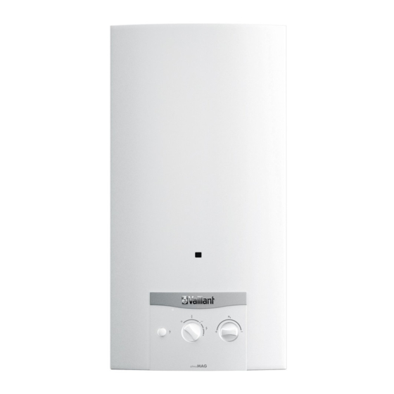
- Page 1 Installation and maintenance instructions atmoMAG MAG ...4/1 Z BE (de), DE Publisher/manufacturer Vaillant GmbH Berghauser Str. 40 D-42859 Remscheid Tel. +49 21 91 18‑0 Fax +49 21 91 18‑2810 info@vaillant.de www.vaillant.de...
-
Page 2: Table Of Contents
Contents Contents 8.12 Checking the water valve ........18 8.13 Checking the heat input ........18 Safety ..............3 8.14 Setting the maximum heat input ......19 Action-related warnings ......... 3 8.15 Checking the maximum heat input ...... 20 Intended use ............3 8.16 Completing inspection and maintenance work .. -
Page 3: Safety
Safety 1 Safety Intended use also covers installation in ac- cordance with the IP code. Action-related warnings Any other use that is not specified in these in- Classification of action-related warnings structions, or use beyond that specified in this The action-related warnings are classified in document shall be considered improper use. - Page 4 1 Safety ▶ Use a telephone outside the building to to corrosion on the product and in the flue inform the emergency service department system. of the gas supply company. ▶ Ensure that the supply of combustion air is always free of fluorine, chlorine, sulphur, 1.3.3 Risk of death from leaks if the dust, etc.
-
Page 5: Regulations (Directives, Laws, Standards)
Safety 1 ▶ Install the necessary safety devices in the system. ▶ Observe the applicable national and inter- national laws, standards and guidelines. 1.3.12 Risk of being burned or scalded by hot components ▶ Only carry out work on these components once they have cooled down. -
Page 6: Notes On The Documentation
2 Notes on the documentation Notes on the documentation Information on the Meaning data plate Observing other applicable documents Minimum heat input min. ▶ You must observe all the operating and installation in- Maximum permissible water pressure w max. structions included with the system components. Serial number 7th to 16th digit = product article number Storing documents... -
Page 7: Ce Label
Set-up 4 Set-up Applicability: MAG 144/1 Z(E-BE) OR MAG 144/1 Z(E-DE) Checking the scope of delivery OR MAG 144/1 Z(LL-DE) Remove the product from its box. OR MAG 144/1 Z(P-BE) Check that the scope of delivery is complete and intact. 4.1.1 Scope of delivery Num-... -
Page 8: Minimum Clearances
4 Set-up Minimum clearances Minimum clearance 50 mm 180 mm; optimum approx. 250 mm 20 mm; optimum approx. 50 mm 500 mm in front of the heat generator to enable easy access for maintenance work (may be provided by an opening door). It is not necessary to maintain a clearance between the product and components made of combustible materials that go beyond the minimum clearances. -
Page 9: Dimensions
Set-up 4 Dimensions Applicability: MAG 114/1 Z(E-BE/FR) OR MAG 114/1 Z(E-DE) OR MAG 114/1 Z(LL-DE) OR MAG 114/1 Z(P-BE/FR) Ø110 min. 20 min. 20 172,5 61,4 Height, dimension A Germany Belgium MAG 114/1 Z(E-BE/FR) 658 mm MAG 114/1 Z(E-DE) 658 mm MAG 114/1 Z(LL-DE) 658 mm MAG 114/1 Z(P-BE/FR) - Page 10 4 Set-up Applicability: MAG 144/1 Z(E-BE) OR MAG 144/1 Z(E-DE) OR MAG 144/1 Z(LL-DE) OR MAG 144/1 Z(P-BE) Ø133,5 min. 20 min. 20 61,4 172,5 Height, dimension A Germany Belgium MAG 114/1 Z(E-BE/FR) 658 mm MAG 114/1 Z(E-DE) 658 mm MAG 114/1 Z(LL-DE) 658 mm MAG 114/1 Z(P-BE/FR)
-
Page 11: Requirements For The Installation Site
Installation 5 Requirements for the installation site Installing the product casing ▶ Select the installation site so that the pipes can be easily routed (gas supply, water supply and drain). ▶ Do not install the product above an appliance whose use may damage the gas-fired instantaneous water heater (e.g. -
Page 12: Information On Liquid Gas Operation
5 Installation Integration into a solar system Caution. Risk of material damage due to the gas The inlet temperature must not exceed 45 °C. leak-tightness test. The hot water temperature must not exceed 60 °C. ▶ At a test pressure of >11 kPa (110 mbar), gas Install thermostatic 3-way valves. -
Page 13: Connecting The Flue Pipe
10 minutes). Initial start-up must be carried out by a customer service ▶ Block off the flue gas route with a Vaillant flue gas re- technician or a qualified competent person. strictor, for example. Also observe the documentation ▶... -
Page 14: Checking The Gas Flow Pressure
After each time you eliminate a fault, check that the flue 1.7–2.5 kPa (17–25 mbar) gas sensor is working without any problems. 2.0-3.0 kPa (20-30 mbar) ▶ If you are unable to eliminate the fault, contact Vaillant Liquid gas Customer Service. 2.5–4.5 kPa (25–45 mbar) Inspection and maintenance ▶... -
Page 15: Procuring Spare Parts
Inspection and maintenance 8 carried out earlier, depending on the results. You can find the inspection and maintenance work table in the ap- pendix. Procuring spare parts The original components of the product were also certified by the manufacturer as part of the declaration of conformity. If you use other, non-certified or unauthorised parts during maintenance or repair work, this may void the conformity of the product and it will therefore no longer comply with the... -
Page 16: Cleaning The Burner
8 Inspection and maintenance Cleaning the burner Use a brass wire-brush to carefully remove combustion residues from the burner without damaging the burner. Clean the jets, injectors and burner rails with a soft brush and blow out any dust or dirt outside the install- ation room from the outside to the inside using com- pressed air. -
Page 17: Removing The Down-Draught Diverter
Inspection and maintenance 8 Removing the down-draught diverter Removing the heat exchanger Remove the cables from the flue gas sensor. Remove two screws each from the fixing plates on the heat exchanger. Remove two screws each for securing the down- draught diverter on the back panel of the product. -
Page 18: Cleaning The Heat Exchanger
8 Inspection and maintenance 8.10 Cleaning the heat exchanger ure selector spindle, remove these and clean the tem- perature selector spindle. Use a spray of water to rinse through the fins of the Check the stuffing box for tightness. If a stuffing box is heat exchanger. -
Page 19: Setting The Maximum Heat Input
Inspection and maintenance 8 Conditions: The deviation is greater than ±5% Note Deviations of ±10% are permitted. ▶ Check whether the correct burner jets have been used in the injector rail for the burner by comparing the labels on the burner jets with the specifications in the tables of gas ▶... -
Page 20: Checking The Maximum Heat Input
If the measured values do not match the values in the the burner pressure. tables of gas settings in the appendix, do not start up the product. Report this to Vaillant Customer Service. Connect a U-tube manometer (resolution at least 0.1 bar). -
Page 21: Appendix
Comment Starting up the product Checking that the flue gas sensor See section "Checking that the flue gas Vaillant flue gas restrictor works correctly sensor works correctly". Check the entire gas route for tightness Use leak detection spray or a leak Leak detection spray/leak detector detector. -
Page 22: C Tables Of Gas Settings
Appendix Symptom Possible cause Measure ▶ The product switches off during Cable break or short circuit in Check how the cables are laid. operation. the cable on the safety cut-out or flue gas sensor. The safety cut-out or flue gas Check the safety cut-out and flue gas sensor. -
Page 23: E Inspection And Maintenance Interval
Appendix Burner pressure Gas family Burner pressure for nominal heat input 11-4/1 14-4/1 Natural gas 2E (G20) 1.12 kPa (11.2 mbar) 1.38 kPa (13.8 mbar) Natural gas 2E+ (G25) 1.48 kPa (14.8 mbar) 1.85 kPa (18.5 mbar) Liquid gas 3P (G31) 3.17 kPa (31.7 mbar) 3.45 kPa (34.5 mbar) Inspection and maintenance interval... -
Page 24: F Technical Data
Appendix Technical data Technical data – General MAG 114/1 Z(E- MAG 114/1 Z(E-DE) MAG 114/1 Z(LL- MAG 114/1 Z(P- BE/FR) BE/FR) Designated country (designation BE, FR BE, FR in accordance with ISO 3166) Approved unit categories (BE), II (FR) (BE), II (FR) 2E+3P 2ELL 3P... - Page 25 Appendix MAG 114/1 Z(E- MAG 114/1 Z(E-DE) MAG 114/1 Z(LL- MAG 114/1 Z(P- BE/FR) BE/FR) Min. permissible water pressure 27 kPa 27 kPa 27 kPa 27 kPa when the temperature se- (270 mbar) (270 mbar) (270 mbar) (270 mbar) w min. lector is positioned at "warm"...
- Page 26 Appendix MAG 114/1 Z(E- MAG 114/1 Z(E-DE) MAG 114/1 Z(LL- MAG 114/1 Z(P- BE/FR) BE/FR) CO₂ content at min. heat output 2.70 % 2.70 % 2.70 % 2.70 % Max. flue gas mass flow rate 6.40 g/s 6.40 g/s 6.40 g/s 6.40 g/s Min.
- Page 27 Appendix MAG 114/1 Z(E- MAG 114/1 Z(P- MAG 144/1 Z(E-BE) MAG 144/1 Z(P-BE) BE/FR) BE/FR) Air requirement for combustion at 31.1 m³/h 31.1 m³/h 41.6 m³/h 41.6 m³/h min. heat input CO₂ content at max. heat output 5.67 % 5.67 % 5.50 % 5.50 % CO₂...
- Page 28 N.V. Vaillant S.A. Golden Hopestraat 15 B-1620 Drogenbos Tel. 2 3349300 Fax 2 3349319 Kundendienst / Service après-vente / Klantendienst 2 3349352 info@vaillant.be www.vaillant.be Vaillant Deutschland GmbH & Co.KG Berghauser Str. 40 D-42859 Remscheid Telefon 021 91 18‑0 Telefax 021 91 18‑2810 Auftragsannahme Vaillant Kundendienst 021 91 5767901 info@vaillant.de www.vaillant.de ©...