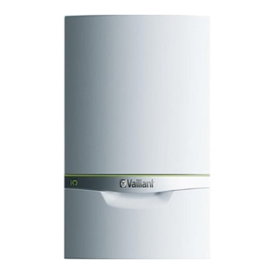
Vaillant ecoTEC exclusive 835 Installation And Maintenance Instructions Manual

Vaillant ecoTEC exclusive 835 Installation And Maintenance Instructions Manual

Table of Contents

Advertisement

ecoTEC exclusive
VUW 356/5‑7 (H-GB) ecoTEC exclusive 835
VUW 436/5‑7 (H-GB) ecoTEC exclusive 843
en Installation and maintenance instructions

Advertisement

Table of Contents
loading

Summary of Contents for Vaillant ecoTEC exclusive 835

  • Page 1 VUW 356/5‑7 (H-GB) ecoTEC exclusive 835 VUW 436/5‑7 (H-GB) ecoTEC exclusive 843 en Installation and maintenance instructions...
  • Page 2: Table Of Contents

    Installation and maintenance Restarting the installation assistants ....27 Test programmes..........27 instructions Using check programmes ........27 Contents Checking and treating the heating water/filling and supplementary water ........27 Filling the condensate siphon ......28 Safety ..............4 Filling the condensate siphon ......28 Intended use ............
  • Page 3 13.7 Replacing defective components......40 13.8 Completing repair work........43 13.9 Checking the product for leak-tightness ....43 Decommissioning..........43 14.1 Temporarily decommissioning the product..43 14.2 Permanently decommissioning the product..43 Recycling and disposal........43 Appendix ................44 Inspection and maintenance work ....44 Installer level –...
  • Page 4: Safety

    Safety Qualification The person carrying out the work described Intended use here must have completed professional train- The product is intended as a heat generator ing. The competent person must demon- for sealed heating installations and for do- strably have all of the knowledge, skills and mestic hot water generation.
  • Page 5 ▶ Do not use any electrical switches, mains To ensure that the combustion air supply is plugs, doorbells, telephones or other com- sufficient during open-flued operation: munication systems in the building. ▶ Ensure that the air supply to the product's ▶...
  • Page 6: Regulations (Directives, Laws, Standards)

    To prevent material damage: ▶ Do not install the product in rooms prone to frost. You can find a list of relevant standards at: https://www.vaillant.co.uk/standards 1.3.11 Safety devices ▶ Install the necessary safety devices in the installation. 1.3.12 Risk of death from leaks if the...
  • Page 7: Guarantee And Customer Service

    To register your Vaillant appliance visit: https://self-service.vaillant.co.uk/warranty-registration Vaillant is a licensed member of the Benchmark Scheme. Benchmark places responsibilities on both manufacturers and installers. The purpose is to ensure that customers are provided with the correct equipment for their needs, that it is installed, commissioned and serviced in accordance with the manufacturer’s instructions by a competent person approved at the time by the Health and...
  • Page 8: Technical Data

    Technical data – G20 power/loading G20 Technical data * The lowest nominal heat output may be higher than the Technical data – General value in the technical data, depending on the design of the system and the current operating status. VUW 356/5‑7 VUW 436/5‑7 (H-GB)
  • Page 9: Notes On The Documentation

    Article num- Gas Council Technical data – Hot water handling mode Number VUW 356/5‑7 (H-GB) 0010017064 47-044-66 VUW 356/5‑7 VUW 436/5‑7 ecoTEC exclusive 835 (H-GB) (H-GB) ecoTEC ecoTEC VUW 436/5‑7 (H-GB) 0010017065 47-044-67 exclusive 835 exclusive 843...
  • Page 10: Product Design

    Product design If the boiler does not resume normal operation press the reset button. If the boiler does not resume normal operation after this call your Installation/Servicing company or Vaillant service. 5.6.2 Overheating Safety The boiler software is designed to recognise the potential for an overheat lockout and will shutdown before this happens.
  • Page 11 of warm cloths on the pipe. After pressing reset the boiler should restart. 0020193968_05 ecoTEC exclusive Installation and maintenance instructions...
  • Page 12: Set-Up

    Set-up Dimensions Scope of delivery Check that the scope of delivery is complete and intact. Num- Designation Heat generator Installation set containing the following: - Unit mounting bracket - Expansion relief valve connection pipe - Gas stopcock - Gas connection pipe, dia. 20 mm - Domestic hot water connection pipe - Cold water connection pipe - Service valve...
  • Page 13: Installation Site

    Installation site Air/flue pipe 6.6.1 Regulation This boiler is not suitable for outdoor installation. This boiler may be installed in any room. However if the boiler is being Different flue outlet configurations can be carried out. installed in a room containing a bath or shower it must only be installed in zones 2 or 3.
  • Page 14 6.6.2 Position of the air/flue terminal 6.6.2.1 Positioning the terminal of a fan-supported flue system Installation site Dimensions Adjacent to a boundary. 300 mm The dimension below eaves, balconies and car ports can be reduced to this value, as long as the flue terminal is 25 mm extended to clear any overhang.
  • Page 15 Installation site Dimensions The dimension below eaves, balconies and car ports can be reduced to this value, as long as the flue terminal is 25 mm extended to clear any overhang. External flue joints must be sealed with suitable silicon sealant. Above adjacent ground or balcony.
  • Page 16: Using The Installation Template

    6.6.3.3 Vertical Concentric Flue ⌀ 60/100 mm or 6.6.3 Flue Configuration Description ⌀ 80/125 mm (C33 type installation) 6.6.3.1 Horizontal Concentric Flue ⌀ 60/100 mm or ⌀ 80/125 mm (C13 type installation) Gasket (fitted) Consult the separate installation manual for air/flue gas sys- Note tems supplied with your appliance for all possibilities and as- If the terminal is at less than 1.80 m from the...
  • Page 17: Removing/Installing The Front Casing

    6.10 Removing/installing the side section Note the total weight of the product. Only use fixing material that is permitted for the wall. 6.10.1 Removing the side section If required, ensure that mounting apparatus on-site has sufficient load-bearing capacity. Wall-mount the product as shown in the illustration. Removing/installing the front casing 6.9.1 Removing the front casing...
  • Page 18: Installation

    – Installation Draining cocks at the lowest points in the heating installation (→ current version of "BS 2879") – Installation requirements A stopcock on the cold water connection – A stopcock in the gas pipe 7.1.1 Information on liquefied petroleum gas Check that the volumetric capacity of the expansion operation vessel is sufficient for the system volume.
  • Page 19: Checking The Gas Line For Leak-Tightness

    Connect the product to the gas line in accordance with the recognised rules of technology. Remove the residues from the gas line by blowing through the gas line beforehand. Purge the gas line before start-up. Checking the gas line for leak-tightness ▶...
  • Page 20 7.8.1.1 Direct Connection to internal soil and vent drain pipe freezing. Fitting an extra trap may cause the boiler siphon to work incorrectly. stack ▶ Follow the instructions listed here and observe directives and local regulations on condensed water discharge. ▶...
  • Page 21 7.8.1.7 External termination into rain water down Preferred option for external termination pipe 7.8.1.5 External termination into soakaway Ø32mm ≤ 3 m ≤ 3 m < 500 mm Ø22mm 100 mm Ø 32mm Ø12 NB only combined foul/rainwater drain 7.8.1.8 Additional methods of introducing air breaks Ground (either/or) Bottom of sealed tube Seal...
  • Page 22: Flue Installation

    Flue installation 7.10.1 Opening the electronics box 7.9.1 Installing and connecting the air/flue pipe You can find out which air/flue pipes may be used by consulting the enclosed set-up instructions for the air/flue system. Observe the information on positioning the air/flue ter- minal.
  • Page 23 ▶ Make sure that the rated voltage of the Carry out the wiring. (→ Page 22) mains is 230 V. Close the electronics box. Observe the flue-gas connection that is required on a room-sealed air/flue system. (→ Page 22) Observe all valid regulations. Make sure that the nominal mains voltage is 230 V.
  • Page 24 7.10.7.1 Using the auxiliary relay Connect an additional component directly to the integ- rated auxiliary relay using the grey plug on the PCB. Carry out the wiring. Activate the component via D.026, see section "Adapt- ing to the heating installation". 7.10.7.2 Using the VR 40 ("2 in 7"...
  • Page 25: Operation

    Operation Operating concept The operating concept and the read-off and setting facilities of the operator level are described in the operating instruc- tions. An overview of the reading and setting options for the in- staller level is included in the table in the appendix. Installer level –...
  • Page 26: Start-Up

    ▶ Start-up Fill the heating installation. (→ Page 29) 9.3.3 Purging Carrying out the initial start-up Unlike in the Check programs menu, to purge the Initial start-up must be carried out by a customer service system, start check programme P.00 by pressing technician or an authorised competent person using the Benchmark Checklist.
  • Page 27: Restarting The Installation Assistants

    Condition: Liquid gas set Display Meaning ▶ P.04 Reset eGas CH (Central Heating) check programme: If you have selected the "liquid gas" gas type, after the Calling up the programme deletes all of the CH cor- start-up process is complete, affix the enclosed "Liquid rection values that have been saved from previous gas"...
  • Page 28: Filling The Condensate Siphon

    Filling the condensate siphon Total Water hardness at specific system volume heating > 20 l/kW Validity: VUW 356/5‑7 (H-GB) ecoTEC exclusive 835 output ≤ 20 l/kW > 50 l/kW ≤ 50 l/kW mol/ mol/ mol/ CaCO₃ m³ CaCO₃ m³ CaCO₃...
  • Page 29: Preventing Low Water Pressure

    9.10 Preventing low water pressure To ensure that the heating installation operates smoothly, the indicator on the pressure gauge must point to the upper half of the grey area or to the middle of the bar graph display in the display (marked by the dashed limit values) when the heating installation is cold.
  • Page 30: Purging The Heating Installation

    9.15.2 Checking the gas flow rate Check whether all thermostatic radiator valves and both service valves on the product are open. The gas flow rate has been set during production and does Connect a hose to the drain valve that is located at the not require adjustment.
  • Page 31 ▶ Do not start up the product. ▶ If you cannot correct the failure, notify the gas supply company and proceed as follows: ▶ End the check programme P.01. ▶ Allow the boiler to cool down by allowing pump overrun to operate for a minimum of two minutes.
  • Page 32: Checking Leak-Tightness

    9.15.4.1 Calibrating the heat generator and Note measuring the CO/CO₂ content and gas All radiators should be cold before you start flow in domestic hot water mode calibration. This ensures that the heat volume can be transferred to the heating The following steps are only required if calibration and installation.
  • Page 33: Thoroughly Flushing The Heating Installation ("Hot")

    9.16.1 Checking the heating mode 10.1 Calling up diagnostics codes Make sure that there is a heat requirement. The setting options for more complex installations can be found in the Diagnostics menu. Call up Live monitor. ◁ If the product is working correctly, the display Menu →...
  • Page 34: Setting The Maintenance Interval

    10.2.2 Resetting the remaining burner anti-cycling 10.4.1 Remaining feed head of the pump time 10.4.1.1 Pump characteristic line 835 (VUW 356/5-7) Alternatives 1: ▶ Navigate to Menu → Reset anti-cycl. time. ◁ The current burner anti-cycling time appears in 100% the display.
  • Page 35: 11 Handing Over To The End User

    Pres- Position of the sure Notes/application adjusting screw in MPa (mbar) If the radiators do not heat Right-hand stop up sufficiently at the default 0.035 (turned all the setting. In this case, you (350) way down) must set the pump to the maximum speed.
  • Page 36: 12 Inspection And Maintenance

    12 Inspection and maintenance 12.6 Electronics self-test Menu → Installer level → Test programs → Electronics 12.1 Complete Service Interval Record section self-test ▶ After servicing, complete the relevant Service Interval You can use the electronics self-test to check the PCB. Record section of the Benchmark Checklist located on the inside back pages of this document.
  • Page 37 Never undo the four nuts on the stud bolt (1) or tighten them. Clean the heating coil (2) of the heat exchanger (3) us- ing water or, if required, vinegar (to a maximum of 5% Unscrew the retaining screw (2) and remove the air acid).
  • Page 38: Clean The Condensate Siphon And Check The Condensate Discharge Pipe

    12.8.4 Installing the compact thermal module 12.10 Draining the product Close the service valves of the product. Start the check programme P.06 (diverter valve mid- position). Open the drain valves. Make sure that the cap of the automatic air vent on the internal pump is open so that the product can be drained fully.
  • Page 39: 12.12 Checking The Impeller Sensor

    12.18 Checking the product for leak-tightness Retighten the cap nuts and the lock nuts on the cold water inlet. ▶ Check that the product is leak-tight. (→ Page 32) Open the cold water stop valve. 12.12 Checking the impeller sensor 13 Troubleshooting ▶...
  • Page 40: Checking Service Messages

    13.2 Checking service messages 13.5 Resetting parameters to factory settings ▶ Navigate to Menu → Installer level → Diagnostics To obtain further information, call up the Live monitor. menu → D.096 Reset to factory settings? and con- (→ Page 25) firm by pressing Condition: S.40 is displayed Press...
  • Page 41 13.7.2 Replacing the gas valve assembly Switch off heating mode and domestic hot water gener- ation (→ Operating instructions). Remove all plugs from the fan (1). Unscrew the three screws between the mixture pipe and the fan flange. Replace the defective fan. Reinstall the new fan in the reverse order.
  • Page 42 To make the installation easier, use only the lubricant that may be included with the Vaillant spare part. If no lubricant is included with the Vaillant spare part, use only water If you are replacing the PCB, remove the coding resist- or commercially available soft soap.
  • Page 43: Completing Repair Work

    Observe all relevant regulations. 13.7.8 Replacing the all-gas sensor ▶ For detailed information refer to www.vaillant.co.uk. Remove the air intake pipe; see Removing the com- pact thermal module (→ Page 36). Undo the screws (3) just enough so that you can pull out the all-gas sensor by the cable (2).
  • Page 44: Appendix

    Appendix Inspection and maintenance work The table below lists the manufacturer requirements with respect to minimum inspection and maintenance intervals. If na- tional regulations and directives require shorter inspection and maintenance intervals, you should observe these instead of the intervals listed. Each time inspection and maintenance work is carried out, carry out the required preparatory and com- pletion work.
  • Page 45: B Installer Level - Overview

    Maintenance work Interval Run the test operation on the product/heating installation including hot Annually water generation (if available) and, if required, purge the product/heating installation Completing inspection and maintenance work Annually Checking the gas type Annually Checking the CO/CO₂ content following maintenance work Annually Checking leak-tightness Annually...
  • Page 46 Setting level Values Default Unit Increment, select, explanation setting Min. Max. – Auxiliary relay 1 = Circulation pump 2 = External pump 3 = Cylinder charging pump 4 = Extractor hood 5 = External solenoid valve 6 = External fault message 7 = Solar pump (not active) 8 = eBUS remote control (not active) 9 = Legionella protection pump (not active)
  • Page 47: C Overview Of Diagnostics Codes

    Setting level Values Default Unit Increment, select, explanation setting Min. Max. – Auxiliary relay 1 = Circulation pump 2 = External pump 3 = Cylinder charging pump 4 = Extractor hood 5 = External solenoid valve 6 = External fault message 7 = Solar pump (not active) 8 = eBUS remote control (not active) 9 = Legionella protection pump (not active)
  • Page 48 Values Factory Code Parameter Unit Increment, select, explanation setting setting Min. Max. – D.005 Heating target flow temper- Current value °C Target flow temperature value (or Not ad- ature target return value) justable – D.006 Outlet temperature target Current value °C Domestic hot water temperature Not ad-...
  • Page 49 Values Factory Code Parameter Unit Increment, select, explanation setting setting Min. Max. – D.018 Pump operating mode Setting 1 = Comfort (continuously operat- ing pump) The internal pump is switched on when the heating flow temperature is not at Heating off and the heat requirement is enabled via an ex- ternal control 3 = Eco (intermittently operating...
  • Page 50 Pump mode 0 = Relay with disable facility 1 = PWM with disable facility – D.047 Current outside temperat- Current value °C (with Vaillant weather-compensated Not ad- control) justable – D.050 Offset min. speed 3000 Nominal value set in factory –...
  • Page 51 Values Factory Code Parameter Unit Increment, select, explanation setting setting Min. Max. – – D.069 Number of second start Current value Unsuccessful ignitions at 2nd at- Not ad- attempts tempt justable – D.070 3-way valve operation 0 = Normal operating mode 1 = Mid-position (parallel operation) 2 = Permanent heating position D.071...
  • Page 52 Values Factory Code Parameter Unit Increment, select, explanation setting setting Min. Max. – – D.091 Status DCF77 Current value 0: No reception Not ad- justable 1: Reception 2: Synchronised 3: Valid – – D.092 actoSTOR communication Current value actoSTOR module detection Not ad- status justable...
  • Page 53: D Status Codes - Overview

    Status codes – Overview Note Since the code table is used for various products, some codes may not be visible for the product in question. Status code Parameter Meaning Heating mode S.00 Heating: No heat demand Heating: No heat demand S.01 Heating mode: Fan start-up Heating mode: Fan start-up...
  • Page 54: E Overview Of Fault Codes

    Flow/return sensor test running, heating demands are S.98 Flow/return temperature sensor self-test blocked. S.99 Vaillant self-test Self-test Overview of fault codes Note Since the code table is used for various products, some codes may not be visible for the product in question.
  • Page 55 Code Parameter Possible causes F.20 Safety switch-off: Temperature limiter Incorrect earth connection between cable harness and product, flow or return NTC defective (loose connection), stray spark via ignition cable, ignition plug or ignition electrode Only in liquefied petroleum gas operation or in cascade mode: The differential pressure sensor was not replaced with a bypass valve;...
  • Page 56 Code Parameter Possible causes F.55 Fault: CO sensor Checking the cable harness All-gas sensor defective, replace the all-gas sensor Electronics defective, replace the PCB F.56 Safety switch-off: CO limit exceeded Safety shutdown: CO limit value exceeded A component in the combustion regulation is defective –...
  • Page 57: F Check Programmes - Overview

    Code Parameter Possible causes F.81 Fault: cylinder charging pump Only in conjunction with F.91 Cylinder is not fully charged after specified time. – Check cylinder charging sensor and cylinder sensor – Air in the actoSTOR pump – Inspect cable harness for pump –...
  • Page 58: G Function Menu - Overview

    Function menu – Overview Function menu Meaning T.01 Internal pump The internal pump is switched on and off. T.02 3-way valve The prioritising diverter valve is moved to the heating or domestic hot water position. T.03 Fan The fan is switched on and off. The fan runs at maximum rotational speed. T.04 Cylinder charging pump The cylinder charging pump is switched on and off.
  • Page 59: H Wiring Diagrams

    Wiring diagrams Wiring diagram 12 - 35 kW +24V Hallsignal Masse X100 X40 X51 X100 230V~ 0020193968_05 ecoTEC exclusive Installation and maintenance instructions...
  • Page 60 Main PCB Bus connection (digital room thermostat/control) Control panel PCB Prioritising diverter valve All-gas sensor Water pressure sensor Gas valve assembly Warm start sensor Outdoor temperature sensor, flow temperature Domestic hot water sensor sensor (optional, external), DCF receiver Internal heating circuit flow rate sensor Circulation pump remote control Impeller sensor Return temperature sensor...
  • Page 61: Wiring Diagram ≥ 37 Kw

    Wiring diagram ≥ 37 kW +24V Hallsignal Masse X100 X40 X51 X100 230V~ Main PCB All-gas sensor Operator control panel PCB Gas valve assembly 0020193968_05 ecoTEC exclusive Installation and maintenance instructions...
  • Page 62 Outdoor temperature sensor, flow temperature Water pressure sensor sensor (optional, external), DCF receiver Warm start sensor Circulation pump remote control Hot water sensor Coding resistor Internal heating circuit flow rate sensor Return temperature sensor Impeller sensor Flow temperature sensor Gas family coding resistor Additional relay (select via D.026) Surface-mounted thermostat/burner off Circulation pump connection...
  • Page 63: I Commissioning Checklist

    Commissioning Checklist Benchmark Commissioning & Warranty Validation Service Record It is a requirement that the boiler is installed and commissioned to the manufacturers’ instructions and the data fields on the commissioning checklist completed in full. To instigate the boiler warranty the boiler needs to be registered with the manufacturer within one month of the installation.
  • Page 64 GAS BOILER SYSTEM COMMISSIONING CHECKLIST & WARRANTY VALIDATION RECORD Address: Boiler make and model: Boiler serial number: Commissioned by (PRINT NAME): Gas Safe registration number: Company name: Telephone number: Company email: Company address: Commissioning date: Heating and hot water system complies with the appropriate Building Regulations? Time, temperature control and boiler interlock provided for central heating and hot water Boiler Plus requirements (tick the appropriate box(s)) Weather compensation...
  • Page 65 SERVICE & INTERIM BOILER WORK RECORD It is recommended that your boiler and heating system are regularly serviced and maintained, in line with manufacturers’ instructions, and that the appropriate service / interim work record is completed. Service provider When completing a service record (as below), please ensure you have carried out the service as described in the manufacturers’ instructions. Always use the SERVICE/INTERIM WORK ON BOILER Date: SERVICE/INTERIM WORK ON BOILER...
  • Page 66 SERVICE & INTERIM BOILER WORK RECORD It is recommended that your boiler and heating system are regularly serviced and maintained, in line with manufacturers’ instructions, and that the appropriate service / interim work record is completed. Service provider When completing a service record (as below), please ensure you have carried out the service as described in the manufacturers’ instructions. Always use the SERVICE/INTERIM WORK ON BOILER Date: SERVICE/INTERIM WORK ON BOILER...
  • Page 67: J Commissioning Flow Chart

    Commissioning Flow Chart PRIOR TO CO AND COMBUSTION RATIO CHECK NOTE The boiler manufacturer’s installation instructions should have been followed, gas type verified and gas THE AIR GAS RATIO VALVE IS FACTORY supply pressure/rate checked as required prior to commissioning. SET AND MUST NOT BE ADJUSTED As part of the installation process, especially where a flue has been fitted by persons other than the DURING COMMISSIONING UNLESS THIS...
  • Page 68: Index

    Index Draining, product ..............38 Electronics box, closing............22 Electronics box, opening ............. 22 Air ratio setting .............. 31–32 Electronics self-test ............. 36 Air/flue pipe, connecting ............22 Expansion vessel, replacing..........42 Air/flue pipe, horizontal wall duct......... 16 Air/flue pipe, installing ............22 Fan, replacing..............
  • Page 69 Opening, electronics box............. 22 Operating concept ............... 25 Overheating protection ............10 PCB and display, replacing ..........42 PCB or display, replacing ............ 42 Power supply............... 22 Pre-charge pressure for the internal expansion vessel, checking ................39 Preparing, maintenance work..........36 Preparing, repair work ............
  • Page 72 Supplier Vaillant Ltd. Nottingham Road Belper Derbyshire DE56 1JT Telephone 0330 100 3461 info@vaillant.co.uk www.vaillant.co.uk 0020193968_05 Publisher/manufacturer Vaillant GmbH Berghauser Str. 40 D-42859 Remscheid Tel. +492191 18 0 Fax +492191 18 2810 info@vaillant.de www.vaillant.de © These instructions, or parts thereof, are protected by copyright and may be reproduced or distributed only with the manufacturer's written consent.

This manual is also suitable for:

Ecotec exclusive 843Vuw 356/5 7Vuw 436/5 7

Table of Contents