
Related Manuals for Basler acA1300-75gc


Summary of Contents for Basler acA1300-75gc
- Page 1 README How to Join a Basler blaze camera and a Basler ace/ace 2 Camera Applicable to blaze, ace and ace 2 camera models only Document Number: AW001666 Version: 01 Language: 000 (English) Release Date: 01 February 2021...
- Page 2 Contacting Basler Support Worldwide Europe, Middle East, Africa Basler AG An der Strusbek 60–62 22926 Ahrensburg Germany Tel. +49 4102 463 515 Fax +49 4102 463 599 support.europe@baslerweb.com The Americas Basler, Inc. 855 Springdale Drive, Suite 203 Exton, PA 19341 Tel.
-
Page 3: Table Of Contents
AW00166601000 Readme Table of Contents Introduction ..........................2 Hardware Requirements ......................2 Camera and Lens Recommendations ................. 3 Suggested Printing Parameters ................... 3 Assembly Instructions ......................4 How to Join a Basler blaze camera and a Basler ace/ace 2 Camera... -
Page 4: Introduction
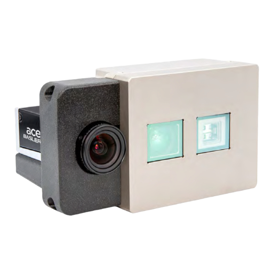
This readme describes how to build a joint camera system consisting of a Basler ace/ace 2 area scan camera and a Basler blaze 3D ToF camera. Such a camera assembly will allow you to create color point clouds or add high-resolution 2D images to your 3D application to enhance your pattern recognition or object detection algorithms. -
Page 5: Camera And Lens Recommendations
AW00166601000 Readme 2.1 Camera and Lens Recommendations The mounting bracket is suitable for any ace or ace 2 GigE camera. However, Basler recommends the following components for most RGB-D applications: acA1300-75gc ace camera Order number: 106757 acA1920-51gcBAS ace 2 camera Order number: 107823 ... -
Page 6: Assembly Instructions
The mounting bracket has been designed for minimum distance between the optical axes of both cameras. Therefore, the thumbscrews of the Basler C125 lens have to be removed as they would interfere with the body of the blaze camera or the mounting bracket. - Page 7 AW00166601000 Readme Revision History Document Number Date Changes AW00166601000 1 Feb 2021 Initial release version of this document. How to Join a Basler blaze camera and a Basler ace/ace 2 Camera...