
Related Manuals for KYE Systems Corp. Genius SW-HF 5.1 5005


Summary of Contents for KYE Systems Corp. Genius SW-HF 5.1 5005
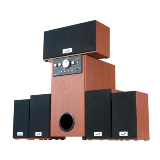
- Page 1 Service Guide SW-HF 5.1 5005 SERVICE GUIDE KYE SYSTEM CORP Version 1.1 Page 1 of 30...
-
Page 2: Revision History
Service Guide SW-HF 5.1 5005 Revision History Version Date Change 26/07/2007 11/12/2007 Satellite panel length LOGO position Cancel G9 cable, add 3 pcs of converter cables Reduce the satellite size a little Version 1.1 Page 2 of 30... -
Page 3: Table Of Contents
Service Guide SW-HF 5.1 5005 Table of Contents Revision History………………………………………………………………….2 Table of contents……………………………………………………………...…3 Getting Start…………………………………………………….………………...4 Conventions Used in this Guide…………………………………………….…4 Safety Precautions………………………………………………………………4 Chapter 1. How to Handle Defective Returns……………………………….5 1.2 Problem………………………………………………………………………6 1.2.1 No power,LED (indicator)…………………………………….……7 1.2.2 No sound…………………………………………………………….…….8 1.2.3 Front channel no sound (including either FR or FL no sound)….……9 1.2.4 Rear channel no sound (including either RR or RL no sound)...……10 1.2.5 Center no sound…………………………………………………………11 1.2.6 Woofer no sound………………………………………………….…..…12... -
Page 4: Getting Start
Service Guide SW-HF 5.1 5005 Getting Started Conventions Used in the Guide Pay Special Attention: Instructions that are important to remember and may prevent mistakes. Caution: Information that, if not followed, may result in damage to the product. Safety Precautions The following precautions should be observed in handing the speaker described in this guide: Place the speakers on a flat, level and stable surface. -
Page 5: Chapter 1. How To Handle Defective Returns
Service Guide SW-HF 5.1 5005 Chapter 1. How to Handle Defective Returns 1.1 Overview Receiving Defective speaker from customers Verifying problems Proceeding Necessary tests Function NG Function OK Function NG Analyzing possible Malfunction cause Deciding & proceeding the Rectification methods Replace necessary Defective parts Verifying problems... -
Page 6: Problem
Service Guide SW-HF 5.1 5005 1.2 Problems Item Problem Description 1.2.1 No power,LED (indicator) 1.2.2 No sound 1.2.3 Front channel no sound (including either FR or FL no sound) 1.2.4 Rear channel no sound (including either RR or RL no sound) 1.2.5 Center no sound 1.2.6... -
Page 7: No Power,Led (Indicator
Service Guide SW-HF 5.1 5005 *Attention Please follow the numbered sequence marked within parenthesis given in individual Flow chat in that this is the best-recommended sequence to rectify the problems. 1.2.1 No power,LED (indicator)unlighted No power, LED (indicator) Problem Analyze Defective or Fuse Defective... -
Page 8: No Sound
Service Guide SW-HF 5.1 5005 1.2.2 no sound no sound Problem SW-HF5.1 CON PCB 1. Defective IC2 on PCB damaged, Assembled line -HF5.1 INPUT PCB 2. Defective IC1, IC2 SW dry-soldered or defectively 3. Defective IC1, IC2, IC3, IC4, IC5, IC6, IC7, IC8, short-circuited connected Analyze and... -
Page 9: Front Channel No Sound (Including Either Fr Or Fl No Sound)
Service Guide SW-HF 5.1 5005 1.2.3 Front channel no sound (including either FR or FL no sound ) Front channel no sound (including either FR or FL no sound) Problem Defective 1.defective IC1, PCB damaged, Defective connection components relating to IC1 and dry-soldered or connection of front front... -
Page 10: Rear Channel No Sound (Including Either Rr Or Rl No Sound)
Service Guide SW-HF 5.1 5005 1.2.4 Rear channel no sound (including either RR or RL no sound) Problem or RL no sound) Rear channel no sound (including either RR Defective damaged, 1. Defective IC1, IC2 or Defective connection of rear dry-soldered components relating to connection of rear... -
Page 11: Center No Sound
Service Guide SW-HF 5.1 5005 1.2.5 Center no sound Problem Center no sound Poor soldering, Defective Defective Defective IC1, Analyze and broken, or short connection connection components relating to IC1 identify the circuit center speaker center audio and IC2 on SW-HF5.1 INPUT causes cables cables, or JACK... -
Page 12: Woofer No Sound
Service Guide SW-HF 5.1 5005 1.2.6 Woofer no sound Problem Woofer no sound Defective 1. Defective IC1, IC2 or components Defective Analyze and connection of relating to IC1 and IC2 on SW-HF5.1 dry-soldered, connection of identify the speaker INPUT PCB broken, woofer causes... -
Page 13: Input No Sound
Service Guide SW-HF 5.1 5005 1.2.7 input no sound Problem input no sound Defective Defective input SW-HF5.1 INPUT Analyze and components relating to PCB soldering points RCA jack identify the inputs on SW-HF5.1 broken, dry soldering causes INPUT PCB or short circuit Check Check Check and replace... -
Page 14: Remote Control No Use
Service Guide SW-HF 5.1 5005 1.2.8 Remote control no use Problem Remote control no use Defective SW-HF Defective REM1,IC2, Low power of Defective soldering R18,EC3,CC4 on the battery conductive Analyze and battery spring broken, or its SW-HF5.1 CON PCB rubber identify the other some keys... -
Page 15: Noise
Service Guide SW-HF 5.1 5005 1.2.9. Noise Problem Noise Defective or dry-soldering Defective VR4, VR3, VR2 Broken or dry-soldering IC2 or components relating VR4,VR3,VR2 Analyze and IC2 on SW-HF5.1 INPUT identify the causes Resolder or replace Resolder or replace Check and replace Solutions Version 1.1 Page 15 of 30... -
Page 16: Led Indicators No Light
Service Guide SW-HF 5.1 5005 1.2.10. LED indicators no light Problem LED indicators no light Defective , dry-soldering, or broken LED1,LED2,LED3, Analyze and LED4,LED5,LED6 or the components relating to them identify the causes Check and replace Solutions Version 1.1 Page 16 of 30... -
Page 17: Chapter 2. Specification
Service Guide SW-HF 5.1 5005 Chapter 2. Specifications Satellite NOMINAL NO DESCRIPTION UNIT LIMIT 1 RATED OUTPUT POWER @THD 10% ±5% 2 SENSITIVITY(1KHz)@RATED O/P POEWR 380 380 ±10% 3 SENSITIVITY(1KHz)@1W O/P POWER 80 ±10% MAX INPUT LEVEL@1% THD 280 280 ±10% 100 100 ±20... -
Page 18: Woofer
Service Guide SW-HF 5.1 500 Chapter 2 Specifications Woofer DESCRIPTION UNIT NOMINAL LIMIT RATED OUTPUT POWER@100Hz(10%THD) ±5 SENSITIVITY(100Hz)@RATED O/P POWER ±10 SENSITIVITY (100Hz)@1W O/P POWER ±5 MAX INPUT LEVEL@1% THD ±9 0.15 DISTORTION@100Hz REF.O/P POWER ≤0.5 ±10 FREQUENCY RESPONSE(100Hz -3DB) ±20 S/N RATIO@100Hz RATED O/P POWER ≥75... -
Page 19: Chapter 3 Block Diagram
Service Guide SW-HF 5.1 5005 Chapter 3 Block diagram Version 1.1 Page 19 of 30... -
Page 20: Chapter 4 Exploded View
Service Guide SW-HF 5.5005 Chapter 4 Exploded view Subwoofer Version 1.1 Page 20 of 30... -
Page 21: Satellite (Center)
Service Guide SW-HF 5.1 5005 Chapter 4 Exploded view Satellite (Center) Version 1.1 Page 21 of 30... -
Page 22: Satellite (Front)
Service Guide SW-HF 5.1 5005 Chapter 4 Exploded view Satellite (Front) Satellite (Rear) Version 1.1 Page 22 of 30 Service Guide SW-HF 5.1 5005... -
Page 23: Chapter 5 Part List
Chapter 5 Part list Woofer Part NO. Ref. NO Description standby keystroke, SW-HF5.1 5005, silver, HIPS EP40754134A Keystroke, SW-HF 5.1 5005,silver ,HIPS EP40754133A smaller knobs, SW-HF5.1 5005, silver, HIPS EP40754136A big knob, SW-HF5.1 5005, silver , HIPS EP40754135A LED cover in the big knob, transparent, ABS EP41410031 Front panel , SW-HF5.1 5005, black color EP40318001... -
Page 24: Center
Service Guide SW-HF 5.1 5005 Chapter 5 Part list Center Part NO. Ref. NO Description cloth, black EP64000167 EP16050041 center driver unit A-115-3, 4"4 Ω15W EP24150024 screw, 3.5*18TA tweeter A-52-2A , 2"8Ω 10W EP16020043 EP24100082 screw, 3.5*14PA EP53K86J01A center wood box, K86V2 paper tube, φ22*φ25*30mm EP41590057 EP1A090065... -
Page 25: Chapter 6 Important Notes
Service Guide SW-HF 5.1 5005 Chapter 6. Important Notes 6.1 Packing requirement for sending the PCB assembly by post PCB assembly is a kind of sophisticated electronic circuit board. Well packing will be required when sending them by post. *Some sophisticated IC components are mounted on the PCB assembly;... -
Page 26: Chapter 7 Circuit Diagram
Service Guide SW-HF 5.1 5005 Chapter 7. Schematic diagram SW-HF 5.1 INPUT PCB Version 1.1 Page 26 of 30... -
Page 27: Sw-Hf 5.1 Con Pcb
Service Guide SW-HF 5.1 5005 Chapter 7. Schematic diagram SW-HF 5.1 CON PCB Version 1.1 Page 27 of 30... -
Page 28: Sw-Hf 5.1 Amp Pcb & Sw-Hf 5.1 Satsp Pcb
Service Guide SW-HF 5.1 5005 Chapter 7. Schematic diagram SW-HF 5.1 AMP PCB Version 1.1 Page 28 of 30... -
Page 29: Sw-Hf 5.1 Swamp Pcb
Service Guide SW-HF 5.1 5005 Chapter 7. Schematic diagram SW-HF 5.1 SWAMP PCB & SW-HF 5.1 SATSP PCB Version 1.1 Page 29 of 30... -
Page 30: Sw-Hf 5.1 Rem Pcb
Service Guide SW-HF 5.1 5005 Chapter 7. Schematic diagram SW-HF 5.1 REM PCB (remote control) Version 1.1 Page 30 of 30...
Need help?
Do you have a question about the Genius SW-HF 5.1 5005 and is the answer not in the manual?
Questions and answers