scope ConneXions CX6 Installation & User Manual
Radio paging transcoder dc, multi port version
Hide thumbs
Also See for ConneXions CX6:
- Installation & user manual (14 pages) ,
- Installation & user manual (15 pages)

Related Manuals for scope ConneXions CX6


Summary of Contents for scope ConneXions CX6
- Page 1 Connexions CX6 Radio Paging Transcoder DC, Multi Port Version Installation & User Manual CX6DCred Issue 2 www.acornfiresecurity.com...
- Page 2 For UK equipment, Scope has no control of the use and application of the frequencies issued by OFCOM. Some equipment that is licensed may have greater protection than other equipment which is operated on a WT Act License Exempt basis.
- Page 3 Liability Scope does not accept liability for any damage or injury, howsoever caused as the result of misuse of this equipment. It is the responsibility of the user to ensure that the equipment is operated in the manner for which it was intended and that it is the correct item of equipment for the required task.
-
Page 4: System Overview
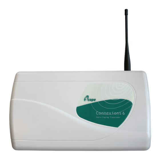
ConneXions CX6 DC, Multi Port Version System Overview The Scope Connexions 6 is a POCSAG data display radio paging system which can be used to transmit both text and numeric messages direct to pocket pagers carried by individuals or entire groups. - Page 5 ConneXions CX6 DC, Multi Port Version Some major points to consider when installing equipment: Never install antennas near or adjacent to telephone, public address or data communication lines or overhead power cables. Avoid, where ever possible, running antenna coax alongside other cables.
- Page 6 ConneXions CX6 DC, Multi Port Version Carefully lift off the cover and set aside. The transmitter should be fixed to an even wall surface using suitable screws fitted through the holes provided in the chassis plate. Hold the chassis up to the chosen location and with the aid of a pencil mark the position of the mounting holes.
- Page 7 ConneXions CX6 DC, Multi Port Version DIAGRAM 1 CX6DCred Issue 2 Page 6 of 13 www.acornfiresecurity.com...
-
Page 8: Section 2: System Operation
ConneXions CX6 DC, Multi Port Version Section 2: System Operation Confirmation of power connection is by way of the red LED on the base of the transcoder console. Confirmation of transmit is provided by way of the momentary green LED on the base of the transcoder console. - Page 9 ConneXions CX6 DC, Multi Port Version Optional Dry Contacts This option must be specified at time of ordering, along with the pre-programmed messages required. The purchaser should also order the dry contact interface box (Part Code: DC8) for ease of connection to the contact terminals (see Diagram 2).
- Page 10 ConneXions CX6 DC, Multi Port Version As a default, contacts are programmed as Normally Open (N/O), with a repeat transmission every two minutes if still active. For customers who wish to connect directly to PL1, the pinout arrangement on the 9 way D plug is...
-
Page 11: Other Antennas
In the event that a pager requires service, return it directly to Scope (in the pre-addressed service bag supplied with your system) by registered post. Ensure that you carefully fill out the service form provided. -
Page 12: System Specification
330 (L) x 190 (W) x 70 (D) max *dependent on system configuration excluding aerial ** subject to applicable country’s licencing conditions Scope’s policy is one of continuous development and specifications are subject to change without notice CX6DCred Issue 2 Page 11 of 13... -
Page 13: Section 3: Technical Information
ConneXions CX6 DC, Multi Port Version Section 3: Technical Information This section provides a more in depth understanding of how messages are formatted for serial communication from a host. It need only be studied by those intending to write their own serial comm.’s software. - Page 14 To change the transmission baud rate in a message string, placing a letter “N” after the “A” will alter it to 512 baud. Placing a letter “F” after the “A” will alter it to 1200 baud. The default setting for the Connexions CX6 is 512 baud. ************************************************************************...
Need help?
Do you have a question about the ConneXions CX6 and is the answer not in the manual?
Questions and answers