
Related Manuals for SUNWARD SWE20B


Summary of Contents for SUNWARD SWE20B
- Page 1 SWE20B Operator’s Manual (Original Version) SUNWARD INTELLIGENT EQUIPMENT CO., LTD. Sunward Intelligent Industrial Park, Xingsha, Changsha, China June, 2013...
- Page 2 Only original spare parts procured from Sunward are to be used. To use parts of poor quality will be detrimental to machine’s overall performance.
-
Page 3: Table Of Contents
TABLE OF CONTENTS 1. SAFETY RULES........................1 1.1 SAFETY MARK ........................1 1.2 SAFETY LABEL ........................1 1.3 GENERAL SAFETY INSTRUCTION ................. 1 1.4 PREPARE FOR EMERGENCIES ..................2 1.5 WEAR SAFETY PROTECTIVE ARTICLES..............2 1.6 CHECK MACHINE BEFORE START-UP................2 1.7 ADJUST OPERATOR SEAT ....................2 1.8 ENTER OR LEAVE MACHINE CORRECTLY .............. - Page 4 2.3 MONITOR PANEL......................19 2.4 WANE CONTROL PANEL....................20 2.5 START-UP SWITCH ......................21 2.6 HEATER..........................21 2.6.1 WORK THEORY ......................21 2.6.2 INSTALLATION......................22 2.6.3 OPERATION ........................22 2.7 RADIO..........................22 2.8 SEAT ADJUSTMENT ......................23 2.9 PILOT SAFETY LEVER ....................24 2.10 ENGINE ACCELEROGRAPH SPEED CONTROL LEVER..........24 2.11 PILOT OPERATION ......................
- Page 5 5. TRANSPORTATION AND STORAGE................84 6. TROUBLE SHOOTING......................87 7. SPECIFICATIONS......................... 90 7.1 TECHNICAL PARAMETER ..................... 90 7.2 TECHNICAL INTRODUCTION ..................92 7.3 OPERATION PARAMETER ..................... 95 8. ATTACHMENT........................97 8.1 ELECTRIC DRAWING ...................... 97 8.2 FOUR PUMP SYSTEM HYDRAULIC DRAWING ............98 8.3 HYDRAULIC COMPONENT LIST ..................99 9.
-
Page 6: Safety Rules
1. SAFETY RULES 1.1 SAFETY MARK Fig 1-1 is the mark to remind of safety, when you see this mark on the machine or in the manual book; it indicates that the human body is in danger of injury. 1.2 SAFETY LABEL There are various labels at various points of machine, in these labels, various words indicate various hurt risks, such as “DANGER”, “WARNIGN”, “CAUTION”... -
Page 7: Prepare For Emergencies
3) Don’t refit machine without authorization, otherwise it will affect the performance and service life of machine, or may cause human body hurt oreven death. 1.4 PREPARE FOR EMERGENCIES All concerned people should be cautious so as to prevent accident from occurring, and at the same time, deposit first-aid kit and fire extinguisher nearby, and place the phone numbers of hospital and fire department near telephone to ask for help in case of emergency. -
Page 8: Forbid Hitching Other People
1.10 FORBID HITCHING OTHER PEOPLE When the machine is in operation or traveling, prohibit other people except operator staying on the machine. 1.11 KEEP MACHINE AWAY FROM ELECTRICITY TRANSMISSION LINE Any part or load of machine touching electricity transmission line will cause human death or GBH. Prohibit machine or its load being close to electricity transmission line, the machine should be 3 meters away from line. -
Page 9: Operate Digging Work Safely
If signalman is needed, he or she should use hand signal. Only when both signalman and operator understand the meaning of signal, the operator can operate the machine traveling and swinging. Understand all the meanings of flag, mark, and signal, and determine the person who is in charge of signaling. -
Page 10: Avoid Accident By Control Failure
1.15 AVOID ACCIDENT BY CONTROL FAILURE When the machine loses control, if someone tries to mount on or stop machine, it will cause GBH or death. To avoid the machine losing control, pay attention to the following proceedings: Place the machine on horizontal ground, try your best not to stay on slope, and stop machine as following procedures: Lower the bucket to the ground. -
Page 11: Support Machine Correctly
Safety in maintenance If maintenance must be made during engine operation, there must be somebody in cabin. If the machine must be lifted, then the angle between boom and arm must be kept between 90-110° to support the lifted parts stably in maintenance work. Never work under the machine being lifted by boom. -
Page 12: Store Parts Safely
1.21 STORE PARTS SAFELY The stored parts, such as bucket, hydraulic breaker, etc, are likely to fall down, causing GBH or death. By all effective means, store parts and machine safely to avoid falling down. Don’t permit unauthorized people, especially children being closed to the parts storage area. -
Page 13: Beware Of Inhaling Fog Or Exhaust Gas
1.26 BEWARE OF INHALING FOG OR EXHAUST GAS Inhaling engine exhaust gas will cause disease, so much as, or death. If it is necessary to operate machine in the building, open door and window to ensure well ventilation, or use long exhaust pipe to discharge smoke. 1.27 BEWARE OF SCALD During operation, engine oil, gear oil, hydraulic oil will become hot. -
Page 14: Remove Paint Before Welding Or Heating
1.31 REMOVE PAINT BEFORE WELDING OR HEATING Prevent bringing potential poisonous gas and dust. When paint is heated up by welding or by other methods, it will cause poisonous gas. Remove paint as following methods before welding or heating up. Rub out paint with abrasive paper or wheel, during this work, remember to wear regulated respirator to avoid inhaling dust. -
Page 15: Emergency Exit
Before every shift or 8-hour operation, check loosened, twisted, hardened, or cracked cable and wire. Before every shift or 8-hour operation, check lost or damaged connectors. Before operation, tighten, repair, or replace any loosened or damaged cable, wire and connector. If the cable or wire is loosened or twisted, don’t operate the machine. Repair switch Before everyday operation, check the function of key switch and engine emergency stop switch. -
Page 16: Other Safety Marks
Note: it is suggest to wear ear shields for long time operation. The exposure to the vibrations can be considerably reduced observing the following recommendations: -- the correct equipment for the machine and for the work to do; --select the suitable seat, which can reduce the vibration to the operator sufficiently. (remark: the seat provided in the machine has complied with spectral class EM 6 of EN ISO 7096:2008);... - Page 17 Warning: Please stay away from the loader arm clearance area. Warning:Please near away from the rotating area. Warning:Pay attention to machine’s lifting capacity in operation. The lifting capacity is based on the criteria of the machine being level on a firm supporting ground. When the machine is operated in conditions that deviate from these criteria (e.g.
-
Page 18: Machine Familiarization
With Rubber Closed cab swing crawler SWE20B With Rubber Open cab swing crawler Note: The above weight figures are measured with the following five requirements: 1. Diesel oil tank is full (diesel oil instrument displays full); 2. Hydraulic oil is enough; 3. Water tank... -
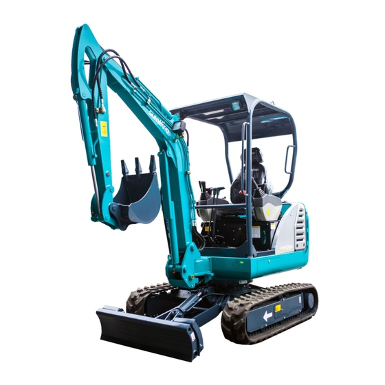
Page 19: Position Of The Various Machine Components
2.1 POSITION OF THE VARIOUS MACHINE COMPONENTS FIG. 2-1 1. Cabin 12. Dozer cylinder 2. Seat 13. Bucket 3. Rear hood 14. Link rod 4. Fuel tank 15. Swing arm 5. Hydraulic cylinder 16. Bucket cylinder 6. Traveling motor 17. Arm 7. -
Page 20: Cabin
2.2 CABIN 1 Monitor 2 Heating/defrost alternation switch 3 Right operating handle 4 Bulldozer/chassis telescopic control rod 6 Engine accelerograph speed control 7 Starting switch 8 Wane control switch 9 Seat 10 Left operating handle 11 Pilot safety rod 12 Assisting control pedal 13 Left-traveling control rod 14 Right-traveling control rod 15 Arm swing control pedal... -
Page 21: Monitor Panel
2.3 MONITOR PANEL — Engine abnormality condition indicator 2 — Electric charging indicator 3 — Engine oil pressure warning indicator 4 — Cooling water temperature warning indicator 5 — Warm-up indicator 6 — High speed traveling indicator 7 —Air filter clogged indicator lamp 8 —Work hour meter 9 —... -
Page 22: Wane Control Panel
8 —Work hour meter The number on this device is the work time of this machine. 9 — Cooling Water temperature indicator This indicates the engine cooling water temperature. The pointer is within green range when the water temperature is normal; if it goes into the red range, it means water temperature is too high; the LCD will flicker with buzzer alarming. -
Page 23: Start-Up Switch
The wiper is likely to freeze up on the glass, any operation of the wiper before it is thawed may cause damage to it. 3- water-jet switch The switch control wiper of cab water-jet, when press this switch, water-jet generator begins to work, and the green lamp turns on, or water-jet be closed. -
Page 24: Installation
For the heating system adopts engine cooling water as heat source, it is connected with water tank, when ambient temperature is lower than 0°C and engine stops working, empty water tank or add antifreeze to water tank in order to prevent heater core crack. -
Page 25: Seat Adjustment
① power key ② band switch ③ system reset key ④ stereo/monophony switch key ⑤ time display and set key ⑥ hand down/minute adjustment key ⑦ hand down/hour adjustment key ⑧ automatic scan store broadcasting station/mute key ⑨ numeric storage, broadcasting station preset key ⑩... -
Page 26: Pilot Safety Lever
Put up recliner knob A, then rotate the backrest to the proper position you want, release the knob to lock the backrest. Caution (1) Only adjust the seat when the driver is in safety status. (2) For slider and recliner adjustment, please make sure the knob in the proper position; only when the adjustment mechanism parts are separate can you do the adjustment. -
Page 27: Pilot Operation
engine revs, and also you can screw handle to adjust accelerograph imperceptibly. 2.11 PILOT OPERATION Operation marks: You should clearly understand the corresponding part of each control lever. The instruction of this manual is established under the international standard. These control levers are used for the operation of boom、arm、bucket、swing、boom swing and dozer (undercarriage extending). - Page 28 The horn button is equipped on the joystick. C. Dozer (undercarriage extension) control pedal This control lever can control the dozer or undercarriage extension by composite operation with the dozer & undercarriage transform switch. (A)-lift the dozer/track becomes narrow (B)-lower the dozer/track becomes wide FIG.2-14 D.
-
Page 29: Open And Close Front Window
Set the pedal to lock position when it is not being used, if any controls should be touched accidentally when the pedal has not been locked, it may cause serious accident! These devices are used to lock the boom swing and assistant pedal. -
Page 30: Accessory And Tool List
2.14ACCESSORY AND TOOL LIST Random accessory list COD. Name Quantity 703201106001 O-ring 703201034501 O-ring 34.5X2.65 703201025001 O-airproof ring 25X2.65 703202033001 combination washer 33 730652000004 Dustproof ring DLW03001 730652000027 Dustproof ring DLW03501 730652000031 Dustproof ring DLW05003 730403000079 Filter-cartridge of oil return EF-133 730401000051 Filter-cartridge of oil absorption SPF-247 305070500060... - Page 31 Tool list COD. Name Quantity 740104000019 Inner hexagon spanner S3 GB5356-85 740104000003 Inner hexagon spanner S4 GB5356-85 740104000004 Inner hexagon spanner S5 GB5356-85 740104000005 Inner hexagon spannerS6 GB5356-85 740104000006 Inner hexagon spanner S8 GB5356-85 740104000007 Inner hexagon spanner S10 GB5356-85 740115000001 double-solid wrench 8-10 740115000022...
-
Page 32: Identifier
2.15 IDENTIFIER Gravity center mark: Pull hook mark: Foot pedal dropping mark: 7 50 6 1 00 2 0 14 8... -
Page 33: Machine Operation
When the machine is used with other purposes not in this manual, you have to get the consent of Sunward or its agents and obey relative regulations in the place where the machine is used. -
Page 34: Operate Engine
Carry out 50-hour and 100-hour maintenance. 3.3 OPERATE ENGINE 3.3.1 Daily inspection 1) Electric system Check whether there are abraded or cracked wire and slack connector or not, and check whether the light can be turned on or off normally. 2) Boom, arm, bucket, dozer blade, sheet metal, track shoe Check whether there are curving, damaged and lost... - Page 35 devices, battery electrolyte acidity and fuses. 3.3.4 Air filter When indicator light comes on, it means that you should maintain or replace filter core. 3.3.5 Oil level in hydraulic oil tank FIG.3-3 Hydraulic oil filling mark: 750 61 002 0 201 Please pay attention to the followings when fill oil to hydraulic oil tank: 1) Place machine on a horizontal ground and retract all hydraulic cylinders, the oil level is not allowed to exceed MAX mark.
- Page 36 3.3.6 Before starting engine 1) Keep pilot valve control lever locked and pilot handle & travel pole neutral. Operator sits on seat. 2) Turn key switch to ON position, all indicator lights come on except engine hour meter and LCD module, buzzer tweets, self inspection is finished after 2 seconds and the monitor system is on normal working condition.
- Page 37 3) Screw key switch to “OFF” position to stop engine, and take out key. 4) Pull pilot control lever to LOCK position. Don’ t stop engine directly when it is fully loaded, stop engine after 5 minutes minimum load operation to unload the heat load and avoid possible damage to engine.
-
Page 38: Travel Control
framework, keep as far as possible away from the battery connection wire end. Start engine. 2) Separate assistant battery First, break black cathode (-) wire away from framework. ② Disjoin the other end of black cathode (-) wire ② from assistant battery. Disjoin red anode (+) wire ①... -
Page 39: Travel With Handle Control
4) Turning with one side crawler (FIG.3-11) Turn left: treadle right pedal 2 forward. (FIG. 3-8) Turn right: treadle left pedal 1 forward. (FIG. 3-8) order protect travel mechanism, avoid turning while backing as possible as you can FIG.3-11 3.4.2 TRAVEL WITH HANDLE CONTROL If the machine hairlike traveling is needed, you can insert two attached handles to carry out hand control. -
Page 40: Travel Speed
Travel direction mark : 3.4.3 TRAVEL SPEED When the machine is traveling, press high/low speed switch ⑤on control panel( FIG 2-5), the shift of travel motor high and low speed is achieved, then the machine can travel at high or low speed. - Page 41 5) If the excavator can’t travel for getting into miriness, you can extend arm and place bucket to ground to lift one side of crawler, then turn the lifted crawler to clean out the bedload. In order to reduce the force enduring of boom and arm, the angle between boom and arm should be in the range of 90°--110°...
-
Page 42: Excavation
3.5 EXCAVATION 3.5.1 Working condition When dig lengthways with backhoe, make the drive wheel backward and guide wheel forward. (as figure) In order to guarantee safety in quarry working, make the drive wheel backward and guide wheel forward. FIG. 3-19 Pilot handles control 1 —... - Page 43 3.5.2 Composite movement of excavator When the machine slews, you can operate the composite movement of boom and bucket. It can operate as follows: bucket digs while arm is flexing; arm digs while lowering boom, etc. Besides the co-operation between right and left handle, pull either of the handles to any diagonal orientation (45°...
- Page 44 5) During work, do your best to avoid pulling the handle to the end, otherwise it will make hydraulic oil overheated and damage components. 6) Slewing is not allowed if bucket has not left the working face. 7) It allows using arm and bucket to impel or level off rideau, but never operate side of bucket to work by slewing force.
- Page 45 Remove any dirt from 8) Lock all the doors and boxes. 9) If you have to park the machine on the slope, use other method to prevent machine from sliding. 3.5.6 Operate on swampy ground 1) Try your best to avoid traveling on swampy ground. 2) Clean crawler frame if the machine works on very soft ground or is stuck.
- Page 46 3.5.9 Operate in water or mud You should note following information when operate in water or mud: ~110 1) The working area should be hard enough to prevent excavator from going down. 20~30cm 2) The water flow should be slow. 3) Undercarriage immerged height should not exceed chain support wheel.
- Page 47 3.5.11 Leveling operation Don’t apply bucket overmuch to level road surface, otherwise excavator will be damaged. Don’t push or pull earth with bucket when the machine travels. Push dozer blade backward to fill and level FIG. 3-29 road. Apply boom, arm, and bucket generally. As the figure shows, place bucket and arm on a line basically.
- Page 48 In order to avoid damaging hydraulic tank, do not bump or tamp the ground with bucket when bucket hydraulic tank is fully extended (bucket fully retracted). Don’t try to extend armfully and drop bucket, penetrate ground with 4) Adjust the digging length and depth every time to bucket teeth to dig up rocks.
- Page 49 3.5.15 Pay attention to the dozer blade position 1) When extend dozer blade, it may collide with boom cylinder or bucket, please pay attention to it. Note 2) When carries out deep digging work, place dozer blade at rear to guarantee safety. FIG.3-35 3.5.16 Prevention measurement for dozer blade 1) Don’t use dozer blade to dig, otherwise it will...
-
Page 50: Lift Work
3.6 LIFT WORK Lifting hook mark : 7 50 6 1 00 2 0 15 2 Follow all safety regulations when the machine lifts objects. Don’t use damaged chain, wire rope, or cord in lifting work. Don’ t move the load suddenly, don’ t move load on the top of human beings, and never permit anybody to be adjacent to the load. -
Page 51: Hydraulic Breaking Operation
3.7 HYDRAULIC BREAKING OPERATION Hydraulic breaking operation tips…if equipped Choose hydraulic breaker with correct dimension and weight. Consult with your dealer. Pump / Main valve section assignment The hydraulic pressure of section AUX (the hydraulic pressure of the breaker section) supplied by P2 is 21 M Pa. - Page 52 cause unusual hose jump, and damage hydraulic breaker or machine. 6) When retract foreside attachment, don’t allow the chisel of breaker to touch boom. 7) Don’t operate hydraulic breaker in water. 8) Don’t lift objects with hydraulic breaker, otherwise it will cause machine upset and (or) breaker damage.
-
Page 53: Boom Swing
Hydraulic breaker operation time percentage (%) FIG.3-42 Replacement interval (hours) 3.8 BOOM SWING The boom swing pedal locates at the position of operator’s right foot, it is used to swing boom, but the superstructure (cabin, engine, etc) won’t slew when operating this pedal. A. -
Page 54: Maintenance
4 MAINTENANCE FIG. 4-1 4.1 CORRECT MAINTENANCE AND INSPECTION PROCEDURE Please read this manual carefully and learn how to maintain excavator correctly. Follow the correct maintenance and inspection procedures in this manual. Check excavator before daily operation. 1) Check monitor. 2) Check all liquid level. - Page 55 Use recommended fuel, hydraulic oil and lubricant. Only use original SUNWARD parts. If user doesn’t use recommended fuel, hydraulic oil, lubricant and original SUNWARD parts, the warranty will automatically be invalid. Never adjust engine rev limiter or hydraulic system safety valve.
- Page 56 4.1.5 Engine maintenance Please carry out periodic maintenance in the engine manual. 4.1.6 Periodic replacement of hydraulic hose 1) Make sure to carry out periodic inspection of machine to guarantee safe operation. If listed parts are damaged, it may cause serious fire. Because it is difficult to judge the aging situation of these parts by vision, you should replace them at listed intervals.
-
Page 57: Maintenance Guide
4.2 MAINTENANCE GUIDE 4.2.1 ADD LUBRICANT GREASE Means that these parts need maintaining when work in water or mud. ★★ Recommended lubricant grease brand and specification Interval(hour) Parts name 1000 2000 Boom platform △ connecting pin Every end pins of boom cylinder △... -
Page 58: Engine Oil
Identifier with butter: 4.2.2 ENGINE OIL Interval (hours) Parts name 8 50 100 250 1000 2000 Check 1. Engine oil ―― △ level 1.6~ Replac 2. Engine oil △★ △ 2.8L Replac 3.Engine oil filter ―― △ Note: ★ means that the engine oil must be replaced after the first 50 hours’ operation of machine. - Page 59 Mobil Mobil 1310 1340 ★ Delvac1330 Germany 15W-40 Fusicov Belgium Fino CF15W-40 Note: The excavator departed from factory has been filled with “★” marked engine oil. Engine oil specification: Be sure engine oil being used must meet following criterion or classification. API classification CD (or higher)….
- Page 60 4) Fill engine oil through filler filter if necessary. Make sure to use recommended oil. Replace engine oil The engine oil and oil filter must be replaced after the first 50 hours’ operation. After first replacement, please carry out replacement as per <YANMAR operation and maintenance manual>.
-
Page 61: Gear Oil
18) Check whether the engine oil pressure indicator light goes out at once, if not, stop engine and check for the reason. 19) Stop engine, take out key from key switch. 20) Check whether there is any leakage at outlet plug. 21) Check oil level on dipstick 4.2.3 GEAR OIL Interval (hours) -
Page 62: Fuel System
4) Shut off engine, and take out key switch. FIG.4-4 5) Pull the pilot control lever to lock position. 6) Open oil level check plug, check oil level. 7) If necessary, fill the filler through oil filler hole ② to the level as the right figure shows.(refer to “gear oil blank”) In the figure: is the reducer oil filler hole,... - Page 63 normal condition; 10 for the winter) only, do not use kerosene. Fueling Be caution about the fuel. Turn off engine before fueling. Do not smoke while fueling the fuel tank or work near the fuel system. 1) Refer to “stop engine” chapter, park the FIG.
- Page 64 Vent water and sediment of the segregator… everyday Vent water and sediment of the segregator…everyday. Shut off engine in a correct manner. Open the vent valve on the bottom of the segregator. Screw the valve anticlockwise for circles, until the valve goes down for 25mm. Vent the water in the catch basin of the filter until pure fuel flows out.
- Page 65 & eroding replace Please use the original components of sunward only. Exhaust air from fuel system. Air in the fuel system will cause stat-up difficulties and abnormal operation of engine. After venting water and sediment from precipitator,...
-
Page 66: Hydraulic System
4.2.5 HYDRAULIC SYSTEM Interval (hours) Parts name 1500 2000 1. Check hydraulic oil level —— 1500 2000 △ ★ 2. Vent sundries of hydraulic oil —— tank △ 3. Replace hydraulic oil 4. Clean oil inhaling filter —— When replacing hydraulic oil 5. - Page 67 Inspection and maintenance of hydraulic system The hydraulic parts will be very hot during operation. Please remember to cool down excavator before inspection or maintenance. 1) Make sure to park the machine on a firm level ground when maintaining hydraulic system. 2) Lower bucket to ground, and stop engine.
- Page 68 Park machine on a level ground. Arm cylinder extracts and bucket cylinder extends completely to fix excavator. Lower bucket to ground. Run engine idle for 5 minutes. Stop engine, and take out key switch. Pull pilot control lever to lock position. Open right side door, check oil level meter.
- Page 69 Replace hydraulic oil…every 2000 or 1500 hours Clean oil inhaling filter …when replace hydraulic oil The hydraulic oil may be hot, cool down before 1) For easy access, rotate superstructure 90 , and park the machine on level ground. 2) Arm cylinder extracts and bucket cylinder extends completely to fix excavator.
- Page 70 6) Connect the clean filter core (or new filter core ) with their connect flange, fasten the fuel tank, then connect the rubber hose. 7) Clean, fit on, and screw down oil outlet plug. 8) Fill the new clean hydraulic oil from point A to the oil tank. Keep the oil level reach the position between the marks of oil level meter.
- Page 71 Every 200 hose material replace hours hose parts protrusion replace(adopt proper hose end and bending bending semidiameter) connector distortion and replace eroding Please original components of sunward only...
-
Page 72: Air Filter
4.2.6 AIR FILTER interval(hour) Parts name 1000 2000 when Clean △ 1.Air filter core indicator light replace After 5 times clean or 1 year operation 2.Air filter and Check the connecting seal △ pipes condition between Replace immediately when crack or leakage is Replace engines detected... - Page 73 10) Cover the back of the shell of the air filter with cloth or adhesive tape to avoid the entering of dust. 11) Clean the interior of the shell. 12) Use dry compress air whose pressure is lower than 686kPa to clean air filter core , first, blow ②...
-
Page 74: Cooling System
4.2.7 COOLING SYSTEM Interval (hours) Parts name 1000 2000 1. Check cooling water level △ 2. Check and adjust fan belt ※ △ tension 3. Replace cooling water △ 4. Clean radiator interior △※ and hydraulic oil exterior When replace cooling water cooler core Only maintain in the first inspection. - Page 75 Check cooling water level…everyday ① Before the system cools down, don’t loosen water filler cover ① radiator. Screw off the cover slowly, release pressure before When engine is running, the cooling water level should reach the lower surface of flume neck. If the water level is lower than the lower surface, add cooling water to water tank.
- Page 76 Replacement of coolant every 1000 hours Shut off engine and cool down the machine before operation. The body、muffler、radiator and other parts of the machine will be very hot when the engine is just stopped, touching these parts may cause serious scald. The cooling water of engine is also very hot, be careful when loosen radiator box cover and venting plug to avoid serious scald by the injection of high temperature and high pressure cooling water.
-
Page 77: Others
11) Check the coolant height, then screw down the water tank cover. 4.2.8 OTHERS Interval (hours) Parts name 1000 2000 1 . Check abrasion and —— △ laxation of bucket teeth 2.Replace bucket When necessary 3.Control lever lubricant When necessary 4.Check track tag △... - Page 78 Various buckets Correct various teeth assembly. Fit the lock pin into the hole completely as instructions. Check the bucket teeth at regular interval to ensure the abrasion, don’t exceed the scheduled limitation. FIG.4-22 Replace bucket Wrong To prevent injury caused by flying off metal scrap when beat the connection rod in or out, wear goggles, safety glasses or other safety instrument.
- Page 79 Lubrication of control lever Park the excavator with engine off, takes out the key, set pilot safety control lever to lock position. If not, the sudden movement of excavator may cause serous damage. FIG.4-25 Add some lubricant to the control lever and pedal if they can not move smoothly.
- Page 80 Check track lag …every 50 hours (or when necessary) Please use wood block, jack or other firm and stable supporter to lift the machine. Never work while there is not enough support of the machine, especially when the hydraulic cylinder is working. There is pressure grease in the track tightening mechanism, the grease pressure relief valve may fly out and cause damage if you do not operate as the follow procedures.
- Page 81 4) Check the track tensity. Replace rubber track Check the rubber track and repair or replace them immediately when following conditions appear. And contact the SUNWARD dealer for repair or replacement. FIG.4-31 1) If the track has been pulled longer and can not recover, it should be replaced immediately.
- Page 82 2) Don’t use the moment in the following table when assembling plastic caps, or the cap may be broken. Contact the SUNWARD dealer or after service department for help when doing this. 3) Use standard pieces of bolts and nuts in the same specification for replacement.
- Page 83 Spanner Screw thread Screw moment(N.m) Screw thread specification(mm) specification M6×1.0 9.8±0.5 12,13 M8×1.25 22.6±1.1 14,17 M10×1.5 47.1±2.4 Thick screw 17,19 M12×1.75 83.4±4.1 thread 19,22 M14×2.0 134.4±6.7 22,24 M16×2.0 207.9±10.4 27,30 M20×2.5 410.9±20.5 12,13 M8×1.0 24.5±1.2 14,17 M10×1.25 50±2.5 17,19 M12×1.5 87.3±4.3 Thin screw thread...
-
Page 84: Maintenance In Special Situation
4.2.9 MAINTENANCE IN SPECIAL SITUATION Operation condition Maintenance 1. Inspect the loose and lost of connector、bolts and nuts, obvious damage and leakage. 2. Clean mud、 stone、 sand grain on the machine, check the Work in mud、water or damage、crack and loose of jointing after work. rain 3.... -
Page 85: Protection For Long Term Store
4.2.10 PROTECTION FOR LONG TERM STORE If the excavator needs to be stored for over 1 month, the following protection should be adopted to maintain its function during the store period. Protection for long term store Maintenance Details Clean machine Completely clean the machine, fix any malfunction. -
Page 86: Transportation And Storage
5. TRANSPORTATION AND STORAGE There is a possibility that the machine will roll, tip over, or fall while loading or unloading it. Therefore, you need to take the following precautions: Select a firm, level surface and keep sufficient distance from the roadside. Use a loading ramp of adequate strength and size. - Page 87 5.3 Loading & unloading The machine should travel at lowest speed on ramps. Turning while traveling on ramps is very dangerous, and it is forbidden. If you must do so, turn the machine back to the ground or truck bed, modify the traveling direction, and then pass the ramps.
- Page 88 1) Set stoppers in front and behind the crawlers. 2) Put a chain or wire rope over the lower frame and the foreside devices and fasten them securely. 5.5 Transportation on highway You must understand and obey the local regulations before transporting the machine on highway.
-
Page 89: Trouble Shooting
6. TROUBLE SHOOTING If malfunction occurs, stop machine immediately, analyze the reason and maintain adjust or repair the machine as following methods, objects and order. Only authorized people can disassemble and repair the hydraulic parts, please consult with manufacturer if mentioned works is necessary. Lower the work equipment or dozer blade to the ground when servicing them and release the residual pressure of hydraulic system: Park the machine on level ground, stop the engine, put the pilot control rod... - Page 90 1. The machine is out of use long time, 1. Operate control levers separates from oil for several times. floats pilot control 2. Check hydraulic control pipeline hydraulic system, low-pressure cylinder,etc. relief valve, and gear 2. No pressure or exceeding Control levers don’t work pump.
- Page 91 Malfunction Reason Resolution feature 1. Control pilot valve malfunction 1. Repair 2. Corresponding commutator valve and 2. Consult with the dealer Track of one side stop valve malfunction doesn’t work or 3. Consult with the dealer 3. Center connector seal damage move very slowly 4....
-
Page 92: Specifications
7. SPECIFICATIONS 7.1 TECHNICAL PARAMETER Engine…………………………………………………………………YANMAR diesel engine Model……………………………………………………………………YANMAR 3TNV70-SSU Displacement………………………………………………………………………………1.16L Number of cylinder………………………………………………………………………………3 Power………………………………………………………………… 13.3 kW/2200rpm Fuel assumption…………………………………………………………………………269g/kw.h Coupling ……………………………………………………… MONOLASTIC 32 Flanschkupplung Radiator………………………………………………………………………………… BC7007-00 Hydraulic device Hydraulic pump…………………………………………………………………… plunger pump Model………………………………………………………………… PVD-OB-19P-6G3-5125Z Flow………………………………………………………………2x9.5+6.7+2.7 cc/rev Work pressure……………………………………………………… 2 1 + 2 1 + 1 8 . 6 + 3 . 9 M P a Multitandem valve……………………………………………………………………... - Page 93 Swing mechanism Maximum output screw moment…………………………………………………………2651N.m Flat rotate speed……………………………………………………………… 0-10.9 Slewing bearing…………………………………………………Single volleyball slewing bearing traveling brake…………………………………………………hydraulic brake “+”spring pressure multiple brake (normally closed) Electric device Battery………………………………………………………………………………1X12V,60Ah Starter…………………………………………………………………………………12V,1.4KW Generator…………………………………………………………………………………12V,40A Fuel device Fuel tank capacity………………………………………………………………………………23L Travel mechanism Speed ratio …………………………………………………………………………………1/31 Maximum output torque moment High speed…………………………………………………………………………1886 N.m Low speed……………………………………………………………………3336Nm Travel speed...
-
Page 94: Technical Introduction
7.2 TECHNICAL INTRODUCTION SWE20B is an all hydraulic track excavator with beautiful appearance, 360° rotatable flat roof, 1080mm long small rear end, all of these ensure the work in limited place. The engine is YANMAR 3 cylinder water-cooling diesel engine which has a normal rated power of 13.3kW/2200rpm. - Page 95 Swing drive Hydraulic swing motor drives the swing supporting of inner joggle through a planetary reducer. The normally engaged brake in drive system can ensure the safety of the machine. Boom swing The design of ultra-large angle boom swing mechanism makes the machine be applied at side ditch, side channel, foot of wall and cliff.
- Page 96 Wide front door can extend to the front and ensure convenient passage. Glass around the cabin and turnover front window provides best view for operator. Cabin seat is designed according to the ergonomics and can provide more comfort. The surface, backrest and rigidity are adjustable and can suit different kinds of requirement from different operator.
-
Page 97: Operation Parameter
7.3 OPERATION PARAMETER 7.3.1 Outline dimension S U N W A R D (2)Working range dimension model SWE20B parameter Outline dimension(length×width×height) 3820X1170X2378 Distance between wheel 1210 Length of track 1537 Turret distance to ground Gyration radius of turret 1122 Chassis width... - Page 98 7.3.2 Operating parameter model SWE20B parameter Max. digging height 3456 Max. unloading height 2425 Max. digging depth 2216 Max. vertical digging depth 1558 Working Max. digging radius 3815 range Max. reach at ground level 3722 Max. lifting height of dozer Max.
-
Page 99: Attachment
8. ATTACHMENT 8.1 ELECTRIC DRAWING... -
Page 100: Four Pump System Hydraulic Drawing
8.2 FOUR PUMP SYSTEM HYDRAULIC DRAWING... -
Page 101: Hydraulic Component List
8.3 HYDRAULIC COMPONENT LIST Name Name oil return filter core diesel engine air filter——breather plunger pump unit oil tank relief valve main valve block pilot filter core center rotation joint pilot solenoid valve travel driving unit two-speed solenoid valve dozer blade cylinder main valve ---- travel operation right joystick... -
Page 102: About Manufacturer
9. ABOUT MANUFACTURER Company: SUNWARD intelligent equipment Co., LTD. Trade mark: Address: 16 LiXiang Road, Xingsha economic and technologic development district, Changsha, Hunan. Tel: 0086-0731-4020688 4020666 Maintenance point: our office in some provinces and cities of China About distributor About distributor...
Need help?
Do you have a question about the SWE20B and is the answer not in the manual?
Questions and answers