
Related Manuals for SUNWARD SWE25UF


Summary of Contents for SUNWARD SWE25UF
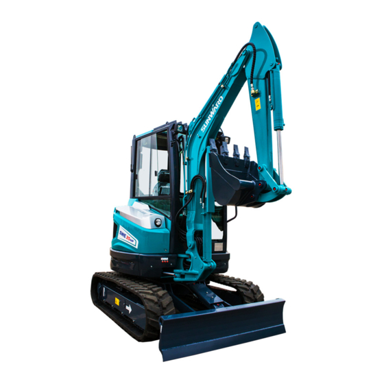
- Page 1 Operation & Maintenance Manual SWE25UF Hydraulic Excavator SUNWARD INTELLIGENT EQUIPMENT CO., LTD. Sunward Intelligent Industrial Park, Xingsha, Changsha, China...
- Page 2 ⚫ Only original spare parts procured from Sunward are to be used. To use parts of poor quality will be detrimental to machine’s overall performance.
-
Page 3: Table Of Contents
TABLE OF CONTENTS 1. SAFETY RULES..............................1 1.1 SAFETY MARK ..............................1 1.2 SAFETY LABEL ............................... 1 1.3 GENERAL SAFETY INSTRUCTION ......................1 1.4 PREPARE FOR EMERGENCIES ........................2 1.5 WEAR SAFETY PROTECTIVE ARTICLES ....................2 1.6 CHECK MACHINE BEFORE START-UP ....................... 2 1.7 ADJUST OPERATOR SEAT .......................... - Page 4 2.1 POSITION OF THE VARIOUS MACHINE COMPONENTS ............... 14 2.2 CABIN ................................15 2.3 START-UP SWITCH ............................16 2.4 MONITOR PANEL ............................17 2.5 WANE CONTROL PANEL ..........................19 2.6 HEATER ................................20 2.6.1 WORK THEORY ............................ 20 2.6.2 INSTALLATION ............................. 20 2.6.3 OPERATION ............................
- Page 5 4.2.9 MAINTENANCE IN SPECIAL SITUATION ..................81 4.2.10 PROTECTION FOR LONG TERM STORE ..................82 4.2.11 HEATER MAINTENANCE ......................... 82 5. TRANSPORTATION AND STORAGE ......................83 6. TROUBLE SHOOTING ............................86 7. SPECIFICATIONS ............................... 90 7.1 TECHNICAL PARAMETER ........................... 90 7.2 TECHNICAL INTRODUCTION ........................
-
Page 6: Safety Rules
1. SAFETY RULES 1.1 SAFETY MARK Fig on the right side is the mark to remind of safety, when you see this mark on the machine or in the manual book; it indicates that the human body is in danger of injury. 1.2 SAFETY LABEL There are various labels at various points of machine, in these labels, various words indicate various hurt risks, such... -
Page 7: Prepare For Emergencies
Only qualified operator is permitted to operate this machine. Keep the machine in good condition as per this manual. 2) Don’t refit machine without authorization, otherwise it will affect the performance and service life of machine, or may cause human body hurt oreven death. -
Page 8: Forbid Hitching Other People
Not allow starting engine with short circuit start-up (including terminal start-up). 1.10 FORBID HITCHING OTHER PEOPLE When the machine is in operation or traveling, prohibit other people except operator staying on the machine. 1.11 KEEP MACHINE AWAY FROM ELECTRICITY TRANSMISSION LINE Any part or load of machine touching electricity transmission line will cause human death or GBH. -
Page 9: Operate Digging Work Safely
⚫ Pay attention to that whether other people stay in work range or not. Ring horn or use other signals to warn before moving the machine. ⚫ If the operator’s vision is blocked when the machine backs, a signalman is needed and the signalman should always be seen. -
Page 10: Avoid Accident By Control Failure
⚫ During operation, prevent boom or arm from colliding with high objects. ⚫ The bucket is only for digging work, do not allow using bucket to work as pneumatic pick or hydraulic breaker does. 1.15 AVOID ACCIDENT BY CONTROL FAILURE When the machine loses control, if someone tries to mount on or stop machine, it will cause GBH or death. -
Page 11: Support Machine Correctly
from the switch. Hang “DO NOT OPERATE” label at control lever. Switch off pilot control. ⚫ Safety in maintenance If maintenance must be made during engine operation, there must be somebody in cabin. If the machine must be lifted, then the angle between boom and arm must be kept between 90-110°... -
Page 12: Store Parts Safely
⚫ Never electricize the frozen battery, otherwise it will explode. The battery should be warmed up to 16° C (60° F). 1.21 STORE PARTS SAFELY ⚫ The stored parts, such as bucket, hydraulic breaker, etc, are likely to fall down, causing GBH or death. ⚫... -
Page 13: Beware Of Inhaling Fog Or Exhaust Gas
Comply with working area rules and concerned asbestos disposal rules, stop other people from entering working area. 1.26 BEWARE OF INHALING FOG OR EXHAUST ⚫ Inhaling engine exhaust gas will cause disease, so much as, or death. ⚫ If it is necessary to operate machine in the building, open door and window to ensure well ventilation, or use long exhaust pipe to discharge smoke. -
Page 14: Avoid Heating Up Inflammable Liquid Pipe
pipe, mount temporary fireproof jacket to protect hose or other materials. 1.30 AVOID HEATING UP INFLAMMABLE LIQUID PIPE Not permit welding inflammable liquid steel pipe or hose. Before welding this kind of pipe or hose, clean this pipe or hose completely with incombustible solvent. 1.31 REMOVE PAINT BEFORE WELDING OR HEATING ⚫... -
Page 15: Emergency Exit
Tighten, repair, or replace any clamps, pipe, hose, oil cooler, and flange bolt of oil cooler. Don’t twist or knock on high-pressured pipe. Don’t assemble twisted or damaged pipeline or hose. ⚫ Inspect short circuit. The short circuit of electric system can cause fire. Before every shift or 8-hour operation, check loosened, twisted, hardened, or cracked cable and wire. -
Page 16: Other Safety Marks
measured according to ISO 6396:2008 considering the method of ISO 3744:2009 under the operation condition required in EU Directive 2000/14/EC and 2005/88/EC, the test results as below: The A-weighted emission sound pressure level at the operator's position is: = 80 dB, which is less than 80 dB required in EN 474-1:2006+A1:2009. The sound power level of the machine is:LWA= 93 dB, which complied with the limit of 2000/14/EC and 2005/88/EC Note:... - Page 17 ⚫ Warning:Please do not stop engine before opening engine hood. ⚫ Warning: Please stay away from the loader arm clearance area. ⚫ Warning:Please near away from the rotating area. ⚫ Warning:Pay attention to machine’s lifting capacity in operation. The lifting capacity is based on the criteria of the machine being level on a firm supporting ground.
-
Page 18: Machine Familiarization
No. allocation allocation With Rubber Cabin swing crawler SWE25UF With Rubber Simple cabin unknown swing crawler Note: The above weight figures are measured with the following five requirements: 1. Diesel oil tank is full (diesel oil instrument displays full); 2. Hydraulic oil is enough ; 3. Water tank... -
Page 19: Position Of The Various Machine Components
2.1 POSITION OF THE VARIOUS MACHINE COMPONENTS FIG. 2-1 1. Cabin 2. Seat 3. Rear hood 4. Fuel tank 5. Hydraulic tank 6. Traveling motor 7. Support wheel 8. Carrier board 9. Rubber crawler 10. Guide wheel 11. Dozer blade 12. -
Page 20: Cabin
15. Swing arm 16. Bucket cylinder 17. Arm 18. Arm cylinder 19. Boom Boom cylinder 22. Swing head 2.2 CABIN 1 Monitor 2 Heating/defrost alternation switch 3 Right operating handle 4 Bulldozer control rod 6 Engine accelerograph speed control 7 Starting switch 8 Wane control switch 9 Seat 10 Left operating handle... -
Page 21: Start-Up Switch
FIG. 2-4 2.3 START-UP SWITCH Do not turn the switch from “off” to “on” or from “on ” to “off” in a short time, or it may cause damage to the engine. P -POSITION(no any action) O -OFF(stop the engine) Ⅰ-ON(connect electric power ) Ⅱ-HEAT(warm-up) Ⅲ... -
Page 22: Monitor Panel
2.4 MONITOR PANEL FIG.2-6 1 — 2 — Automatic idling indicator Working Light indicator 3 — 4 — Engine oil pressure warning indicator Work hour meter 5 — 6 — Engine speed meter Electric charging indicator 7 — 8 — High speed traveling indicator Warm-up indicator 9 —... - Page 23 This symbol light comes on when the working light is on work. 3 — Engine oil pressure warning indicator This indicator indicates the engine oil pressure. When the pressure is normal, there’s no indication; it lights on when the pressure is low and meanwhile, buzzer will warn. 4 —Work hour meter The number on this device is the work time of this machine.
-
Page 24: Wane Control Panel
14 —Working Light control button Press this button, the working light comes up. 15 — Screen switch button Press this button, the screen will show the working hour and speed; press the button again, it will show the time. 16 —Fuel level indicator This indicates the fuel level. -
Page 25: Heater
2-Washer switch This switch turns on and off the water bottle in cabin. When press this button, green lamp turns on, the burner cap on glazing works; press the button again, the burner stops working. 3-heater switch When press this button, green lamp turns on, heater works, the whole cabin starts to be heated. 4—transfer switch Up and down switches are used to control dozer blade and the extension and retraction of chassis separately. -
Page 26: Radio
II-heater fan rotates at high speed 2.7 RADIO Well-known brand radio with strong aseismatic and dustproof capability is beautiful and durable. (Refer to the radio user manual) 2.8 SEAT ADJUSTMENT FIG.2-8 FIG. 2-9 Technical Features (1) The Forward and afterward travel of the seat is 150mm (For:75mm, Aft:75mm) (2) The stepless adjustable angle scope of the backrest: 35 degrees –... -
Page 27: Pilot Safety Lever
“Neutral”,that means there are some malfunctions of the system. Push the safety valve to “Lock” position, turn off the engine switch at once and contact the nearest sunward dealer. 2.10 ENGINE ACCELEROGRAPH SPEED CONTROL LEVER Engine accelerograph lever adjusts engine revs. -
Page 28: Pilot Operation
2.11 PILOT OPERATION Operation marks: You should clearly understand the corresponding part of each control lever. The instruction of this manual is established under the international standard. These control levers are used for the operation of boom、arm、bucket、swing、boom swing and dozer (undercarriage extending). - Page 29 C. Dozer control pedal This control lever can control the dozer or undercarriage extension by composite operation with the dozer (A)-lift the dozer (B)-lower the dozer FIG.2-1 D. Traveling control lever Make sure that the dozer is at the foreside of the operator’s seat before operating the traveling control lever.
-
Page 30: Open And Close Front Window
2.12 OPEN AND CLOSE FRONT WINDOW Front window of the cabin can easily be opened for maintenance and emergency leave. Open the fastening of front window, push the glass window upwards and backwards to the scheduled position, then the front window is fastened. Before closing the front window, firstly, loosen the lock pin, grasp the 2 handles with your hands, lower the front window slowly to the bottom, then lock the lock pin tightly. -
Page 31: Accessory And Tool List
2.14 ACCESSORY AND TOOL LIST Random accessory list COD. Name Quantity 703201069003 O-ring69X5.3 GB/T 3452.1 703201060004 O-ring60X5.3 GB/T 3452.1 703201109001 O-ring109X3.55 GB/T 3452.1 703201050002 O-ring50X3.55 GB/T 3452.1 730652000026 Dustproof ring DLW04002 50X40X5 730652000027 Dustproof ring DLW03501 45X35X4 730652000206 Dustproof ring DLW 60X70X5 302010000683 Adjusting washer(80*36 t0.5) 302010000658... - Page 32 Tool list COD. Name Quantity 740104000019 Inner hexagon spanner S3 GB5356-85 740104000003 Inner hexagon spanner S4 GB5356-85 740104000004 Inner hexagon spanner S5 GB5356-85 740104000005 Inner hexagon spannerS6 GB5356-85 740104000006 Inner hexagon spanner S8 GB5356-85 740104000007 Inner hexagon spanner S10 GB5356-85 740115000001 double-solid wrench 8-10 740115000022...
-
Page 33: Identifier
2.15 IDENTIFIER Gravity center mark: Pull hook mark: 7 50 6 1 00 2 0 14 8 Foot pedal dropping mark:... -
Page 34: Machine Operation
⚫ When the machine is used with other purposes not in this manual, you have to get the consent of Sunward or its agents and obey relative regulations in the place where the machine is used. -
Page 35: Operate Engine
Carry out 50-hour and 100-hour maintenance. 3.3 OPERATE ENGINE Daily inspection 1) Electric system Check whether there are abraded or cracked wire and slack connector or not, and check whether the light can be turned on or off normally. 2) Boom, arm, bucket, dozer blade, sheet metal, track shoe Check whether there are curving, damaged and lost parts or not. - Page 36 Air filter When indicator light comes on, it means that you should maintain or replace filter core. Oil level in hydraulic oil tank FIG.3-3 Hydraulic oil filling mark: 7 50 6 1 00 2 0 20 1 Please pay attention to the followings when fill oil to hydraulic oil tank: 1) Place machine on a horizontal ground and retract all hydraulic cylinders, the oil level is not allowed to exceed MAX mark.
- Page 37 2) Turn key switch to ON position, all indicator lights come on except engine hour meter and LCD module, buzzer tweets, self inspection is finished after 2 seconds and the monitor system is on normal working condition. Start engine 1) Keep pilot valve control lever locked. 2) Turn key switch to ON position.
- Page 38 Don’ t stop engine directly when it is fully loaded, stop engine after 5 minutes minimum load operation to unload the heat load and avoid possible damage to engine. If engine stops with load, remove load and start engine at once. Operate engine for 1 minute at half speed before loading.
-
Page 39: Travel Control
connection. When connecting with excavator framework, keep as far as possible away from the battery connection wire end. ⚫ Start engine. 2) Separate assistant battery ⚫ First, break black cathode (-) wire ② away from framework. ⚫ Disjoin the other end of black cathode (-) wire ② from assistant battery. ⚫... -
Page 40: Travel With Handle Control
4) Turning with one side crawler (FIG.3-11) ⚫ Turn left: treadle right pedal 2 forward. (FIG. 3-8) ⚫ Turn right: treadle left pedal 1 forward. (FIG. 3-8) order protect travel mechanism, avoid turning while backing as possible as you can FIG.3-11 3.4.2 TRAVEL WITH HANDLE CONTROL If the machine hairlike traveling is needed, you can... -
Page 41: Travel Speed
In order to protect travel mechanism, avoid turning while backing as possible as you can. : Travel direction mark 3.4.3 TRAVEL SPEED ⑥ When the machine is traveling, press high/low speed switch on control panel( FIG 2-5), the shift of travel motor high and low speed is achieved, then the machine can travel at high or low speed. - Page 42 redirect the machine. 5) If the excavator can’t travel for getting into miriness, you can extend arm and place bucket to ground to lift one side of crawler, then turn the lifted crawler to clean out the bedload. In order to reduce the force enduring of boom and arm, the angle between boom and arm should be in the range of 90--110...
-
Page 43: Excavation
If the control lever comes back to the neutral position while it is traveling down the slope, the machine will automatically stop. If the machine slides while traveling up on the slope, use the pulling power of the boom to help the machine clime up the slope. If engine stops accidentally while traveling down the slope, set the control lever back to the neutral position to stop the machine, lower the bucket to the ground to block the machine and then restart the machine. - Page 44 Control with left pilot handle Right figure is the obverse view of left pilot handle (when operator sits on the seat). The four movements of handle can make the excavator move as follows. e ——Make the superstructure slew widdershins. f ——Make the superstructure slew clockwise. g ——...
- Page 45 Attention in excavation 1) Operator must wear safety helmet and work clothes, make sure the safety of working area before starting machine. 2) During digging work, the dozer blade should be placed on ground. 3) Other people are not permitted to stand on the machine or within the range of 6 m away from working radius.
- Page 46 4) Turn ignition key to “OFF” position, and take out key. 5) Pull pilot control lever to lock position. 6) Lock all doors and compartments. 7) Inspection after the engine is stop. ⚫ Check the oil tank and water tank, work In cold weather, the excavator should be device, superstructure and infrastructure, parked on hard ground to avoid crawler and...
- Page 47 Lift one side of crawler by using boom and arm. ⚫ Keep the angle between boom and armwithin a range of 90--110, and place the bucket arc on ground. ⚫ Slew superstructure 90 and lower bucket to lift one side of crawler off ground. Don’t dig into the ground with bucket teeth when the machine is in backhoe condition.
- Page 48 Backhoe operation 1) Place the bucket teeth on ground while the angle between bucket bottom and ground is 45. 2) Apply arm to be the main digging force, pull bucket to the machine direction. 3) When dirt adheres to the bucket, remove arm and (or) bucket quickly to throw dirt.
- Page 49 enables the leveling operation more accurate. Prevent collapse 1) Place traveling motor to the rear end of machine to work while the machine and the digging surface are in certain angle or perpendicular. 2) Don’t place machine at the edge of trench or digging area.
- Page 50 6) Don’t make side bucket be loaded. For example, don’t level materials by swinging bucket or side impact objects with bucket. Prevent misuse of machine 1) Don’t treat traveling movement as accessional digging force. Otherwise it will damage the machine. 2) Don’t raise the front and rear of machine and treat the weight of machine as accessional digging force.
-
Page 51: Lift Work
3) When the machine is traveling, dozer blade can’t hook any object, otherwise it will damage dozer blade or crawler system. 4) When prop up machine with dozer blade, the ground should be plane to ensure dozer blade touch ground stably. Be careful when retract foreside working device Don’t allow the bucket to collide with dozer blade. -
Page 52: Hydraulic Breaking Operation
5) Mark hand rigging on the load to ensure the people pulling hand rigging is away from load. 6) Try to lift the load before normal operation. ⚫ Park the machine beside the load. ⚫ Load the machine. ⚫ Lift load to the height of 50mm (2in) off the ground. ⚫... - Page 53 2) Avoid hammering work with hydraulic breaker. Never use boom or arm to break objects, otherwise it will damage machine. 3) Don’t move objects with hydraulic breaker, otherwise it will damage machine. 4) Don’t operate hydraulic breaker when hydraulic cylinder piston retracts or extends fully, avoid damaging hydraulic cylinder or machine.
-
Page 54: Boom Swing
Hydraulic breaker operation time percentage (%) FIG.3-42 Replacement interval (hours) 3.8 BOOM SWING The boom swing pedal locates at the position of operator’s right foot, it is used to swing boom, but the superstructure (cabin, engine, etc) won’t slew when operating this pedal. A. -
Page 55: Maintenance
4 MAINTENANCE FIG. 4-1 4.1 CORRECT MAINTENANCE AND INSPECTION PROCEDURE Please read this manual carefully and learn how to maintain excavator correctly. Follow the correct maintenance and inspection procedures in this manual. Check excavator before daily operation. 1) Check monitor. 2) Check all liquid level. - Page 56 Use recommended fuel, hydraulic oil and lubricant. ⚫ Only use original SUNWARD parts. ⚫ If user doesn’t use recommended fuel, hydraulic oil, lubricant and original SUNWARD parts, the warranty will automatically be invalid. ⚫ Never adjust engine rev limiter or hydraulic system safety valve.
- Page 57 Use fuel and lubricant correctly Always use recommended fuel and lubricant, otherwise it will damage the machine and lose the warranty of Sunward. Preparation for maintenance 1) Place the machine on a hard horizontal ground. 2) Lower the bucket to the ground.
-
Page 58: Maintenance Guide
Recommended periodic hose placement list Replacement Periodic replaced parts Interval Fuel hose (from fuel tank to precipitator, from precipitator to oil Engine 1.5 years feeding pump) Pump inhaling hose (from oil tank to main pump) 2 years Machine Pump output hose (from pump outlet to multipurpose valve) 2 years Body Multipurpose valve hose (from multipurpose valve to working... -
Page 59: Engine Oil
4.2.2 ENGINE OIL Interval (hours) Parts name 8 50 100 250 1000 2000 Check ―― △ 1. Engine oil level 1.6~ Replac △★ △ 2. Engine oil 2.8L Replac ―― △ 3.Engine oil filter Note: ★ means that the engine oil must be replaced after the first 50 hours’ operation of machine. - Page 60 Note: The excavator departed from factory has been filled with “★” marked engine oil. Engine oil specification: Be sure engine oil being used must meet following criterion or classification. API classification CD (or higher)…. ACEA classification E3, E4, E5. JASO classification DH-1 The other technical requirement for engine.
- Page 61 Replace engine oil filter…every 500 hours Steps of replacing engine oil and filter 1) Warm up engine oil before start, but don’t overheat. 2) Park the excavator on a level ground. 3) Lower the bucket to ground. 4) Run engine idle for 5 minutes. 5) Shut off engine, and take out key switch.
-
Page 62: Gear Oil
21) Check oil level on dipstick 4.2.3 GEAR OIL Interval (hours) Parts name 1000 2000 Check — △ 1、Slewing reducer level △ Replace Check — △ 2、Traveling reducer level △ Replace 2x2 L Recommend gear oil Brand Gear oil Manufacturer -20℃--40℃... -
Page 63: Fuel System
In the figure: ② is the reducer oil filler hole, ③ is the oil drainage port. Replace gear oil…every 1000 hours operation 1) Park the excavator on a level ground. The gear oil may be very hot, please start working until the 2) Lower bucket to the ground. - Page 64 Fueling Be caution about the fuel. Turn off engine before fueling. Do not smoke while fueling the fuel tank or work near the fuel system. 1) Refer to “stop engine” chapter, park the excavator properly and turn off the engine FIG.
- Page 65 Vent water and sediment of the segregator… everyday Vent water and sediment of the segregator…everyday. Shut off engine in a correct manner. Open the vent valve on the bottom of the segregator. Screw the valve anticlockwise for circles, until the valve goes down for 25mm. Vent the water in the catch basin of the filter until pure fuel flows out.
- Page 66 & eroding replace Please use the original components of sunward only. Exhaust air from fuel system. Air in the fuel system will cause stat-up difficulties and abnormal operation of engine. After venting water and sediment from precipitator,...
-
Page 67: Hydraulic System
4.2.5 HYDRAULIC SYSTEM Interval (hours) Parts name 1500 2000 —— 1. Check hydraulic oil level 1500 2000 △ ★ 2. Vent sundries of hydraulic oil —— tank △ 3. Replace hydraulic oil —— 4. Clean oil inhaling filter —— When replacing hydraulic oil 5. - Page 68 Inspection and maintenance of hydraulic system The hydraulic parts will be very hot during operation. Please remember to cool down excavator before inspection or maintenance. 1) Make sure to park the machine on a firm level ground when maintaining hydraulic system. 2) Lower bucket to ground, and stop engine.
- Page 69 ⚫ Never distort high pressure hose, the lifetime of distorted hose will be shortened greatly. 8) Fill same brand & spec. hydraulic oil, never use different brands of oil at the same time. When you want to use “recommended hydraulic oil brand and specification” listed oil, make sure to replace all hydraulic oil in the system at the same time.
- Page 70 Vent hydraulic oil tank impurities…every 200 hours Never start engine when the hydraulic oil tank is empty. 1) For easy access, rotate superstructure 90° , and park the machine on level ground. 2) Lower bucket to the ground. 3) Run engine idle for 5 minutes. FIG.
- Page 71 3) Lower the bucket to ground. 4) Run engine at low revs for 5 minutes. replacement interval 5) Stop engine, and take out key. hydraulic oil is different with 6) Pull pilot control lever to lock position. its specification. (Refer to the 7) Screw the screw plug ①...
- Page 72 Exhaust air After the replacement of hydraulic oil, exhaust the air from hydraulic circuit and hydraulic device. If this work has not been properly done, it may cause damage to the hydraulic devices. 1) Release exhaust plug of hydraulic pump. 2) Once hydraulic oil overflows from the exhaust plug plug, screw the plug down immediately.
- Page 73 Every 200 hose material replace hours hose parts protrusion replace(adopt proper hose end and bending bending semidiameter) connector distortion and replace eroding Please original components of sunward only FIG.100 FIG.98 Never start engine when the hydraulic oil tank is empty.
-
Page 74: Air Filter
4.2.6 AIR FILTER interval(hour) Parts name 1000 2000 when △ Clean 1.Air filter core indicator light replace After 5 times clean or 1 year operation 2.Air filter and Check the △ connecting seal condition pipes between Replace immediately when crack or leakage is Replace engines detected... - Page 75 10) Cover the back of the shell of the air filter with cloth or adhesive tape to avoid the entering of dust. 11) Clean the interior of the shell. 12) Use dry compress air whose pressure is lower than 686kPa to clean air filter core ②, first, blow along the flute of interior of the filter core, than blow from outside, finally blow from the interior.
-
Page 76: Cooling System
4.2.7 COOLING SYSTEM Interval (hours) Parts name 1000 2000 △ 1. Check cooling water level 2. Check and adjust fan belt ※1 △ tension △ 3. Replace cooling water 4. Clean radiator △※3 interior and hydraulic oil exterior When replace cooling water cooler core ⚫... - Page 77 Check cooling water level…everyday Before the system cools down, don’t loosen water filler cover ① radiator. Screw off the cover slowly, release pressure before removing the cover. When engine is running, the cooling water level should reach the lower surface of flume neck. If the FIG.98 Never start...
- Page 78 Replacement of coolant every 1000 hours ⚫ Shut off engine and cool down the machine before operation. ⚫ The body、muffler、radiator and other parts of the machine will be very hot when the engine is just stopped, touching these parts may cause serious scald. ⚫...
-
Page 79: Others
engine after the coolant level is stable and stay at the appointed height. 11) Check the coolant height, then screw down the water tank cover. 4.2.8 OTHERS Interval (hours) Parts name 1000 2000 1 . Check abrasion and —— △ laxation of bucket teeth 2.Replace bucket When necessary... - Page 80 Various buckets Correct various teeth assembly. ⚫ Fit the lock pin into the hole completely as instructions. ⚫ Check the bucket teeth at regular interval to ensure the abrasion, don’t exceed the scheduled limitation. Replace bucket FIG.4-22 Wrong To prevent injury caused by flying off metal scrap when beat the connection rod in or out, wear goggles, safety glasses or other safety instrument.
- Page 81 8) Grease pin A and B. Lubrication of control lever Park the excavator with engine off, takes out the key, set pilot safety control lever to lock position. If not, the sudden movement of excavator may cause serous damage. ⚫ engine is just stopped, touching these parts may cause serous scald.
- Page 82 …every 50 hours (or when necessary) ⚫ Please use wood block, jack or other firm and stable supporter to lift the machine. Never work while there is not enough support of the machine, especially when the hydraulic cylinder is working. ⚫...
- Page 83 4) Check the track tensity. Replace rubber track Check the rubber track and repair or replace them immediately when following conditions appear. And contact the SUNWARD dealer for repair or FIG.4-31 replacement. 1) If the track has been pulled longer and can not recover, it should be replaced immediately.
- Page 84 2) Don’t use the moment in the following table when assembling plastic caps, or the cap may be broken. Contact the SUNWARD dealer or after service department for help when doing this. 3) Use standard pieces of bolts and nuts in the same specification for replacement.
- Page 85 Spanner Screw thread Screw moment(N.m) Screw thread specification(mm) specification M6× 1.0 9.8± 0.5 12,13 M8× 1.25 22.6± 1.1 14,17 M10× 1.5 47.1± 2.4 Thick screw 17,19 M12× 1.75 83.4± 4.1 thread 19,22 M14× 2.0 134.4± 6.7 22,24 M16× 2.0 207.9± 10.4 27,30 M20×...
-
Page 86: Maintenance In Special Situation
4.2.9 MAINTENANCE IN SPECIAL SITUATION Operation condition Maintenance 1. Inspect the loose and lost of connector、bolts and nuts, obvious damage and leakage. 2. Clean mud、 stone、 sand grain on the machine, check the Work in mud、water or damage、crack and loose of jointing after work. rain 3.... -
Page 87: Protection For Long Term Store
4.2.10 PROTECTION FOR LONG TERM STORE If the excavator needs to be stored for over 1 month, the following protection should be adopted to maintain its function during the store period. Protection for long term store Maintenance Details Clean machine Completely clean the machine, fix any malfunction. -
Page 88: Transportation And Storage
5. TRANSPORTATION AND STORAGE There is a possibility that the machine will roll, tip over, or fall while loading or unloading it. Therefore, you need to take the following precautions: ⚫ Select a firm, level surface and keep sufficient distance from the roadside. ⚫... - Page 89 Notice: Specific dimension in transport parameter and outline drawing are shown in section 7(technical specification) 5.3 Loading & unloading ⚫ The machine should travel at lowest speed on ramps. ⚫ Turning while traveling on ramps is very dangerous, and it is forbidden. If you must do so, turn the machine back to the ground or truck bed, modify the traveling direction, and then pass the ramps.
- Page 90 5.4 Transportation Put chain and wire rope over the lower frame. Do not put the chain and wire on or through the hydraulic pipes or hoses. 1) Set stoppers in front and behind the crawlers. 2) Put a chain or wire rope over the lower frame and the foreside devices and fasten them securely.
-
Page 91: Trouble Shooting
(2) Grease all the places that need lubrication. (3) Check engine oil level to make sure it is in a stipulated position, otherwise you should fill oil. If there is any water in oil, change oil (4) Turn the key to “ON” position, switch accelerograph button from low to high speed and last for 3 seconds, then switch to low speed and start engine. - Page 92 Malfunctions and solutions Malfunction Reasons Solutions 1. Hydraulic malfunction. 1. Consult with your 2. Air bubble in hydraulic dealer. system. 2. Check whether 3. Aging hydraulic oil, leakage at oil pump inlet degenerative oil mixed with Noisy hydraulic pump and pipeline.
- Page 93 1.Corresponding pilot valve malfunction 2.Hydraulic motor 1.Repair malfunction Slewing platform don’t 2.Consult with your dealer 3.Slewing retarder slew, slew slowly, or slew malfunction 3.Consult with your dealer 4.Slewing bearing not smoothly. 4.Repair malfunction 5.Add lubricant grease 5.Need lubricant grease into the slewing bearing.
- Page 94 Heater Malfunctions and solutions Malfunction Reason Resolution feature 1. Control pilot valve malfunction 1. Repair 2. Corresponding commutator valve and 2. Consult with the dealer Track of one side stop valve malfunction doesn’t work or 3. Consult with the dealer 3....
-
Page 95: Specifications
7. SPECIFICATIONS 7.1 TECHNICAL PARAMETER Engine…………………………………………………………………YANMAR diesel engine Model…………………………………………………………YANMAR 3TNV80f-SPSU Displacement………………………………………………………………………………1.267L Number of cylinder………………………………………………………………………………3 Power…………………………………………………………………………… 14 kW/2400rpm Fuel assumption…………………………………………………………………………272g/kw.h Coupling …………………………………………………MONOLASTIC 32 Flanschkupplung Radiator………………………………………………………………………………BC7039-00 Hydraulic device Hydraulic pump…………………………………………………………………… plunger pump PVD-0B-24P-8G3-5516A Model……………………………………………………… Flow………………………………………………………………2x28.8+19.2+6.5mL/r W o r k p r e s s u r e … … … … … … … … … … … … … … … … … … … … … 2 x 2 1 . 5 / 1 8 M P a M u l t i t a n d e m v a l v e …... - Page 96 Maximum output screw moment…………………………………………………………5099N.m Flat rotate speed………………………………………………………………………8.8rpm Slewing bearing………………………………………………………………… ……Single row traveling brake…………………………………………………hydraulic brake “+”spring pressure multiple brake (normally closed) Electric device Battery………………………………………………………………………………1X12V,63Ah Starter…………………………………………………………………………………12V,1.7KW Generator…………………………………………………………………………………12V,40A Fuel device Fuel tank capacity………………………………………………………………………………26L Travel mechanism Speed ratio ………………………………………………………………………………43.958 Maximum output torque moment High speed…………………………………………………………………………2645 N.m Low speed……………………………………………………………………………1471Nm Travel speed High speed…………………………………………………………………………4.1 km/h...
-
Page 97: Technical Introduction
7.2 TECHNICAL INTRODUCTION SWE25UF is an all hydraulic track excavator with beautiful appearance, 360° rotatable flat roof, 1980mm long small rear end, all of these ensure the work in limited place. The engine is YANMAR 3 cylinder water-cooling diesel engine which has a normal rated power of 14kW/2400rpm. - Page 98 Swing drive Hydraulic swing motor drives the swing supporting of inner joggle through a planetary reducer. The normally engaged brake in drive system can ensure the safety of the machine. Boom swing The design of ultra-large angle boom swing mechanism makes the machine be applied at side ditch, side channel, foot of wall and cliff.
- Page 99 the prototype meets the lowest performance requirements. Wide front door can extend to the front and ensure convenient passage. Glass around the cabin and turnover front window provides best view for operator. Cabin seat is designed according to the ergonomics and can provide more comfort. The surface, backrest and rigidity are adjustable and can suit different kinds of requirement from different operator.
-
Page 100: Operation Parameter
7.3 OPERATION PARAMETER (1)Outline dimension (2)Working range dimension model SWE25UF parameter Outline dimension(length× width× height) 4140X1500X2455 Distance between wheel 1560 Length of track 1990 Turret distance to ground Gyration radius of turret Chassis width 1500 Track width Dimension parameter Ground clearance of chassis... - Page 101 SWE25UF parameter Max. digging height 4355 Max. unloading height 3010 Max. digging depth 2840 Max. vertical digging depth 2580 Working Max. digging radius 4670 range Max. reach at ground level 4775 Max. lifting height of dozer Max. digging depth of dozer Min.
- Page 102 Warning: Pay attention to machine’s lifting capacity in operation Do not attempt to lift or hold any load that is greater than these rated values at their specified lift-point radius and height. The lift point is located at the bucket lifting eye Rated lift capacity(kg) 4.0m 3.0m...
-
Page 103: Attachment
8. ATTACHMENT 8.1 ELECTRIC DRAWING... -
Page 104: Hydraulic Drawing
8.2 HYDRAULIC DRAWING... -
Page 105: Hydraulic Component List
8.3 HYDRAULIC COMPONENT LIST Name Name diesel engine bucket cylinder plunger pump unit boom cylinder pilot oil source block Travel motor dozer blade cylinder pilot safety solenoid valve center rotation joint pilot two-speed solenoid valve swing motor pilot filter cooler arm cylinder main valve Bulldozing hand shank... -
Page 106: About Manufacturer
9. ABOUT MANUFACTURER Company: Hunan SUNWARD intelligent machinery Co., LTD. Trade mark: Address: 16 LiXiang Road, Xingsha economic and technologic development district, Changsha, Hunan. Tel: 0086-0731-83572739 83572783 Maintenance point: our office in some provinces and cities of China About distributor...
Need help?
Do you have a question about the SWE25UF and is the answer not in the manual?
Questions and answers
Is there a manual for swe35uf?
Yes, there is a spare parts catalog available for the SUNWARD SWE35UF hydraulic excavator.
This answer is automatically generated
Здравствуйте. Расход топлива на yf 25 Санвард