Table of Contents
Advertisement
Quick Links
Advertisement
Table of Contents

Related Manuals for GORMAN-RUPP PUMPS S6C1-E35 460/3


Summary of Contents for GORMAN-RUPP PUMPS S6C1-E35 460/3
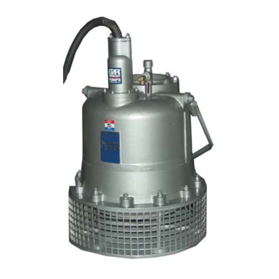
- Page 1 COM‐06100‐01 March 17, 2008 Rev. B 08‐15‐14 INSTALLATION, OPERATION, AND MAINTENANCE MANUAL WITH PARTS LIST SUBMERSIBLE PUMPS MODELS S6C1-E35 460/3 S6C1-E35 575/3 GORMAN‐RUPP PUMPS www.grpumps.com 2014 Gorman‐Rupp Pumps Printed in U.S.A.
- Page 2 Register your new Gorman‐Rupp pump online at www.grpumps.com Valid serial number and e‐mail address required. RECORD YOUR PUMP MODEL AND SERIAL NUMBER Please record your pump model and serial number in the spaces provided below. Your Gorman‐Rupp distributor needs this information when you require parts or service. Pump Model: Serial Number:...
-
Page 3: Table Of Contents
TABLE OF CONTENTS INTRODUCTION ..........PAGE I - 1 SAFETY ‐... - Page 4 TABLE OF CONTENTS (continued) PARTS LISTS: Pump Assemblies ............PAGE E - 3 Terminal Housing and Cable Assemblies .
-
Page 5: Introduction
S SERIES PUMPS OM-06100 INTRODUCTION Thank You for purchasing a Gorman‐Rupp S Se RECORDING MODEL AND ries Pump. Read this manual carefully to learn SERIAL NUMBER how to safely install and operate your pump. Fail ure to do so could result in personal injury or dam Please record the pump model and serial number age to the pump. - Page 6 S SERIES PUMPS OM-06098 damage which could result from failure to follow the procedure. Hazards or unsafe practices which COULD NOTE result in minor personal injury or product or Instructions to aid in installation, operation, and property damage. These instructions de maintenance or which clarify a procedure.
-
Page 7: Safety - Section A
OM-06100 S SERIES PUMPS SAFETY - SECTION A This information applies to the S Series submersible motor driven pumps indi cated on the front cover of this manual. Before connecting any cable to the con Because pump installations are seldom trol box, be sure to ground the control identical, this manual cannot possibly box. - Page 8 S SERIES PUMPS OM-06100 position and locked out, or that the pow er supply to the control box has been otherwise cut off and locked out, before attempting to open or service the pump Obtain the services of a qualified elec assembly.
- Page 9 OM-06100 S SERIES PUMPS cables, or the piping. Attach proper lift ing equipment to the lifting bail fitted on the pump. Lift the pump or component only as high as necessary and keep per Pumps and related equipment must be sonnel away from suspended objects.
-
Page 10: Installation - Section B
OM-06100 S SERIES PUMPS INSTALLATION - SECTION B GENERAL INFORMATION ratings on the control box and incoming pow Review all SAFETY information in Section A. e. Carefully read all tags, decals, and markings Since pump installations are seldom identical, this on the pump, and perform all duties indicated. -
Page 11: Pump Motor Specifications
OM-06100 S SERIES PUMPS equipment as outlined in the National to prevent liquid from wicking through the Electric Code. Follow all safety require cable and into the motor. ments. Failure to observe these require NOTE ments could result in injury or death to Refer to the performance curve in Maintenance personnel. -
Page 12: Positioning The Pump
OM-06100 S SERIES PUMPS Drain the pump and remove all customer‐installed are fitted with a pressure relief valve which will open equipment such as suction and discharge hoses if vapor pressure within the pump motor reaches a or piping before attempting to lift existing, installed critical point. -
Page 13: Electrical Connections
OM-06100 S SERIES PUMPS pump, allowing one pump to feed the other on high The control box is a rainproof enclosure with a pad discharge head applications. lockable front cover. The enclosure is not de signed to be watertight, and should not be sub To determine the size of the discharge connection, merged. -
Page 14: Grounding Methods
OM-06100 S SERIES PUMPS erly grounded. Install and operate the Table B‐3. Pump Voltage Requirements control box in accordance with the Na MAXIMUM tional Electric Code and all local codes. NOMINAL MINIMUM PHASE VOLTAGE VOLTAGE VOLTAGE Failure to follow these could result in in jury or death to personnel. -
Page 15: Pump Power Cable Connections
OM-06100 S SERIES PUMPS b. Driven Electrode: A rod or pipe, 3/4 inch The electrical power used to operate (19,1 mm) in diameter minimum, 8 feet (2,4 m) this pump is high enough to cause inju long, completely driven into the ground. ry or death. -
Page 16: Control Box Specifications
OM-06100 S SERIES PUMPS Connect the pump power cable to the control box NOTE as shown in the wiring diagrams in the control box For reference, internal motor wiring connections manual. Use conduit or cable clamps to secure the are shown in Maintenance and Repair - Section power cable to the control box. -
Page 17: Wiring Diagrams
OM-06100 S SERIES PUMPS PUMP PUMP CONTROL BOX CONTROL BOX TO LEVEL CONTROL CIRCUIT TO LEVEL CONTROL CIRCUIT IN MAIN CONTROL BOX IN MAIN CONTROL BOX LIQUID LEVEL LIQUID LEVEL RANGE RANGE DEWATERING DEWATERING ON (FILLING) ON (FILLING) Figure B-4. Liquid Level Devices cluded with the option before making wir... -
Page 18: Operation - Section C
S SERIES PUMPS OM-06100 OPERATION - SECTION C GENERAL INFORMATION Review all SAFETY information in Section A. The pump motor and control box are not designed to be explosion‐proof. Do not operate in an explosive atmosphere. Any control box used to operate the This pump is designed to handle most pump must be approved by the Gor... -
Page 19: Impeller Rotation
OM-06100 S SERIES PUMPS or thermal protection, or if the pump is operated 4. Check the temperature before ser against a closed discharge valve for an extended vicing. period of time. 5. Vent the pump slowly and cau tiously 6. Refer to instructions in this manual before restarting the pump. -
Page 20: Starting, Stopping And Operational Checks
S SERIES PUMPS OM-06100 this pump is high enough to cause inju ry or death. Make certain that incoming power is off and locked out before inter changing motor leads. Never start the pump more than 6 times per hour. If the pump motor does not cool be tween starts, it will over‐heat, resulting in damage to the motor windings. -
Page 21: Cold Weather Preservation
OM-06100 S SERIES PUMPS COLD WEATHER PRESERVATION To avoid serious damage to the pump, check for unusual noises or excessive vi Do not attempt to thaw the pump by us bration while the pump is running. If noise ing a torch or other source of flame. This or vibration is excessive, stop operation could damage gaskets, O‐rings or heat and refer to the troubleshooting chart in the... -
Page 22: Draining Oil
S SERIES PUMPS OM-06100 month thereafter. Check the motor lubrication level Adding Oil any time the pressure relief valve is activated, and Refer to Table B-2 in INSTALLATION for oil ca replace the oil annually. pacities and positions for filling the seal cavity in your pump. - Page 23 OM-06100 S SERIES PUMPS Table C-1. Pump Oil Specifications Specifications: Type ......Premium high viscosity index, anti‐wear hydraulic oil Viscosity @ 100_F (38_C) .
-
Page 24: Troubleshooting - Section D
OM-06100 S SERIES PUMPS TROUBLESHOOTING - SECTION D Review all SAFETY information in Section A. NOTE Many of the probable remedies listed in the TROU BLESHOOTING CHART require use of electrical test instruments; for specific procedures, see ELECTRICAL TESTING at the end of the chart. TROUBLESHOOTING CHART TROUBLE POSSIBLE CAUSE... - Page 25 S SERIES PUMPS OM-06100 TROUBLESHOOTING CHART (cont'd) TROUBLE POSSIBLE CAUSE PROBABLE REMEDY Discharge head too high. Reduce discharge head or install MOTOR RUNS, BUT PUMP FAILS staging adaptor and additional TO DELIVER pump. RATED DIS Low or incorrect voltage. Measure control box voltage, both CHARGE.
- Page 26 OM-06100 S SERIES PUMPS ELECTRICAL TESTING 3. The pump submerged and running under full load. Make the electrical checks which follow to deter The voltage measured under each condition mine if pump malfunctions are being caused by must be the same. problems in the motor or in the motor cable.
- Page 27 S SERIES PUMPS OM-06100 the other test lead to each of the motor cable should be rechecked regularly. If resistance leads in turn. Note the readings. reads less than 1 megohm, insulation should be checked more closely and frequently. b. Readings will indicate resistance values in both the power cable and motor windings.If resistance reads infinity (1), insulation is c.
-
Page 28: Pump Maintenance And Repair - Section E
PUMP MAINTENANCE AND REPAIR - SECTION E MAINTENANCE AND REPAIR OF THE WEARING PARTS OF THE PUMP WILL MAINTAIN PEAK OPERATING PERFORMANCE. STANDARD PERFORMANCE FOR PUMP MODELS S6C1-E35 460/3 AND S6C1-E35 575/3 Based on 70 F (21 C) clear water at sea level Contact the Gorman‐Rupp Company to verify per... - Page 29 S SERIES PUMPS OM-06100 SECTION DRAWING PARTS PAGE Figure E-1. S6C1-E35 460/3 And S6C1-E35 575/3 Pump Assemblies PAGE E - 2 MAINTENANCE AND REPAIR...
- Page 30 OM-06100 S SERIES PUMPS S6C1-E35 460/3 And S6C1-E35 575/3 Pump Assemblies Parts List (From S/N 1401671 Up) If your pump serial number is followed by an “N”, your pump is NOT a standard production model. Contact the Gorman‐Rupp Company to verify part numbers.
- Page 31 S SERIES PUMPS OM-06100 SECTION DRAWING Figure E-2. Terminal Housing And Cable Assembly PAGE E - 4 MAINTENANCE AND REPAIR...
- Page 32 OM-06100 S SERIES PUMPS Terminal Housing And Cable Assembly Parts List ITEM PART MAT'L PART NAME NUMBER CODE TERMINAL GLAND 11367 13040 POWER CABLE 10325S CABLE GRIP 11227L STUD C0808 17000 HEX NUT 17000 GLAND BUSHING 10758K 19100 TERMINAL WASHER 10659 15991 TERMINAL HOUSING...
- Page 33 S SERIES PUMPS OM-06100 used, disconnect the piping before attempting to PUMP AND SEAL DISASSEMBLY AND move the pump. REASSEMBLY Review all SAFETY information in Section A. Death or serious personal injury and damage to the pump or components can occur if proper lifting procedures Do not attempt to service the pump as...
- Page 34 OM-06100 S SERIES PUMPS Draining Oil From Motor Cavity assembly. Tag electrical circuits to pre vent accidental start‐up. (Figure E-1) Carefully inspect any O‐rings or gaskets before re If motor problems are suspected, remove the mo moval and cleaning to determine if a proper seal tor cavity drain plug (12), and install a short nipple and compression existed prior to disassembly.
- Page 35 S SERIES PUMPS OM-06100 seal spring will be released. Retain the impeller key ring; tension on the seal spring will be released. (58). Inspect the impeller for wear or damage and Remove the spring retainer and seal spring. replace as required. Lubricate the rotor shaft (20) and work oil under the bellows.
- Page 36 OM-06100 S SERIES PUMPS rings and gaskets, and clean the sealing surfaces Neither of the shaft seal assemblies (3 or 4) should of dirt or gasket material. Be careful not to scratch be reused because wear patterns on the finished gasket surfaces.
- Page 37 S SERIES PUMPS OM-06100 Upper Seal Installation Apply a light coating of oil to the seal seating sur face on the shaft, the groove for the retaining ring (Figures E-1 and E-3) (45), and I.D. of the bellows. Position the seal rotat ing portion on the shaft with the seal face down.
- Page 38 OM-06100 S SERIES PUMPS Carefully position the diffuser and stationary seal Remove the block of wood and turn the impeller to components on the rotor shaft, over the studs (49) check for free rotation. and against the intermediate (10). Be careful not NOTE to damage the stationary element already in...
- Page 39 S SERIES PUMPS OM-06100 light coating of `3M Gasket Adhesive No. 847' or handle on the control box is in the off po equivalent compound. sition and locked out, or that the power supply to the control box has been Position the strainer plate (43) over the diffuser, otherwise cut off and locked out, before aligning the bolt holes.
- Page 40 OM-06100 S SERIES PUMPS bore and pull firmly on the cable. (Allow the oil to Disconnect the power cable leads from the termi leak in around the bushing by agitating the cable in nal posts, and separate the terminal plate (13) from the bore.) After the bushing has been loosened, the terminal housing (8).
- Page 41 S SERIES PUMPS OM-06100 seal between the lower ball bearing (36) and the in Stator Removal termediate bore. (Figure E-1) Do not remove the stator (19) unless it is defective (open windings, insulation resistance low, or stator core damaged). If the stator must be removed, re To prevent damage during removal from move the terminal housing as indicated in Termi...
- Page 42 OM-06100 S SERIES PUMPS Relief Valve reassembly (see the parts lists for numbers). (Figure E-1) Stator Installation It is recommended that the relief valve assembly (Figure E-1) (28) be replaced at each overhaul, or at any time the pump motor overheats and activates the valve. NOTE Never replace this valve with a substitute which has Stator installation involves heating the motor hous...
- Page 43 S SERIES PUMPS OM-06100 Position an expandable tool, such as a split disc, rated, replace the shaft and rotor (a single assem approximately 2 inches (51 mm) down inside the bly). stator (opposite the lead wire end), and expand it tightly and squarely on the I.D.
- Page 44 OM-06100 S SERIES PUMPS Clean the bearing cap (35) and position it on the ro precautions printed on solvent contain tor shaft with the gasket surface and screw holes ers. toward the threaded end of the shaft. Position the rotor (20), assembled bearings (21 and 36) and bearing cap (35) on a work surface Heat the lower bearing (36) to a uniform tempera...
- Page 45 S SERIES PUMPS OM-06100 Clean the exterior of the power cable with warm replaced using materials and equipment approved water and mild detergent. Check for obvious physi by Gorman‐Rupp (see the parts list for repair kits). cal damage. Check the cable for continuity and in NOTE sulation resistance (see Electrical Testing in Heat‐shrink tubing must be used to seal the power...
- Page 46 OM-06100 S SERIES PUMPS (399 C) and shrink the tubes around the cable leads and terminal collars. Silicone Sealant Use only Dow‐Corning 737 Silicone Adhe sive (see the Parts List Manual for the part Figure E-4. Silicone Adhesive Sealing number) or potting compound for sealing terminal housing connections.
- Page 47 S SERIES PUMPS OM-06100 Clean and assemble all terminal components as When potting has been completed, leave the ter indicated in Sealing Terminal Plate With Silicone minal plate assembly undisturbed until the potting Adhesive. Use medium grit sandpaper to prepare material has cured.
- Page 48 OM-06100 S SERIES PUMPS the terminal gland flange and the terminal housing Use a manometer with a range of 30 to 0 to 30 inch when the nuts (5, Figure E-2) are fully tightened. es of mercury to perform the test. Do not use a vac uum gauge.
- Page 49 S SERIES PUMPS OM-06100 Table E-1. Vacuum Test Data Pump Duration Seal Cavity Duration Motor Cavity Model (Minutes) Vacuum (Minutes) Vacuum (In. Hg.) (In. Hg.) LUBRICATION mally low, or the color milky or dark, refer to Drain ing Oil From Seal Cavity in this section for instruc tions and troubleshooting tips.
- Page 50 OM-06100 S SERIES PUMPS Table E‐3. Pump Oil Specifications Specifications: Type ......Premium high viscosity index, anti‐wear hydraulic oil Viscosity (SSU @ 104_F [40_C]) .
- Page 53 For Warranty Information, Please Visit www.grpumps.com/warranty or call: U.S.: 419-755-1280 Canada: 519-631-2870 International: +1-419-755-1352 GORMAN‐RUPP PUMPS...
Need help?
Do you have a question about the S6C1-E35 460/3 and is the answer not in the manual?
Questions and answers