Advertisement
Quick Links
H4600A,B; H6600B
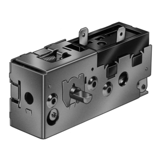
HUMIDITY CONTROLLERS
H4600A End Shaft
APPLICATION
These humidity controllers provide automatic switching
control of humidification or dehumidification equipment.
They are typically used in appliance units such as portable
humidifiers and dehumidifiers, furnace powered
humidifiers, fan ventilation units, etc.
FEATURE
• Long nylon ribbon sensing element provides high
driving force to assure reliable operation, even under
changing ambient temperature conditions.
• Sturdy steel case has corrosion resistant plating.
• Phenolic housing encloses the snapacting switch
with 1/4 in. quick-connect terminals. Switch rated
for line voltage and pilot operation.
• Shaft for adjusting the control point located on either
the end or face of device.
• Positive ON and OFF setting positions permit manual
operation of the controlled equipment.
H4600B Face Shaft
SPECIFICATIONS
IMPORTANT
The specifications given in this publication do not
include normal manufacturing tolerances. There-
fore, this unit may not match the listed specifica-
tions exactly. Also, this product is tested and
calibrated under closely controlled conditions, and
some minor differences in performance can be
expected if those conditions are changed.
Models:
Model
System Control Scale Range (RH)
H4600A
Dehumidifier
H4600B
Humidifier
H6600B
Humidifier
Electrical Ratings (A at 50/60 Hz):
H4600A
120 Vac 240 Vac 120 Vac 240 Vac
Full Load
10.0
Locked Rotor
45.0
Resistive
12.0
Pilot Duty
50 VA at 24 Vac to 240 Vac
Full Load N.O. to C
Full Load N.C. to C
Locked Rotor N.O. to C
Locked Rotor N.C. to C
Resistive N.O. to C
Resistive N.C. to C
Pilot Duty
Set Point Adjustment:
External flat shaft on end or face of control.
PRODUCT DATA
20-80%
10-60%
10-60%
H4600B
5.0
4.4
2.2
22.5
26.4
13.2
6.0
12.0
6.0
H6600B
120 Vac
240 Vac
4.4
2.2
3.0
1.5
26.4
13.2
18.0
9.0
12.0
6.0
3.0
1.5
50 VA at 24 Vac to 240 Vac
68-0064-02
Advertisement

Summary of Contents for Honeywell Home H4600A
- Page 1 Also, this product is tested and calibrated under closely controlled conditions, and some minor differences in performance can be expected if those conditions are changed. H4600B Face Shaft H4600A End Shaft Models: APPLICATION Model System Control Scale Range (RH)
- Page 2 Shipping and Storage Temperature: Enclosed, snap acting. Minus 30 F to plus 150 F [minus 34 C to plus 66 C]. H4600A-SPST makes on RH increase Mounting Means: H4600B-SPST makes on RH decrease Metal case and cover, each having two mounting holes that H6600B-SPDT makes N.C.
- Page 3 Fig. 4. H6600B Internal Schematic. OPERATION H4600A Dehumidifier Controllers The H4600A switch makes contact on a relative humidity Fig. 2. Typical Wiring Diagram for H4600A. rise to the set point to start the dehumidifier. A decrease in relative humidity to the set point minus the differential breaks the switch contact to stop the dehumidifier.
- Page 4 68-0064—02 M.S. Rev. 10-21 | Printed in United States © 2021 Resideo Technologies, Inc. All rights reserved. The Honeywell Home trademark is used under license from Honeywell International, Inc. This product is manufactured by Resideo Technologies, Inc. and its affiliates.


Need help?
Do you have a question about the H4600A and is the answer not in the manual?
Questions and answers